Paper Menu >>
Journal Menu >>
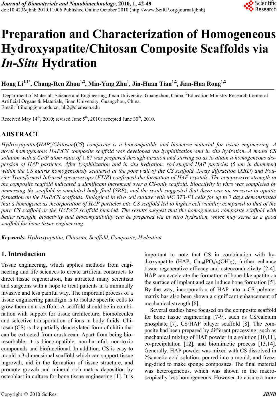 Journal of Biomaterials and Nanobiotechnology, 2010, 1, 42-49 doi:10.4236/jbnb.2010.11006 Published Online October 2010 (http://www.SciRP.org/journal/jbnb) Copyright © 2010 SciRes. JBNB Preparation and Characterization of Homogeneous Hydroxyapatite/Chitosan Composite Scaffolds via In-Situ Hydration Hong Li1,2*, Chang-Ren Zh ou1,2, Min-Ying Zhu1, Jin-Huan Tian1,2, Jian-Hua Rong1,2 1Department of Materials Science and Engineering, Jinan University, Guangzhou, China; 2Education Ministry Research Centre of Artificial Organs & Materials, Jinan University, Guangzhou, China. Email: *tlihong@jnu.edu.cn, hli2@clemson.edu Received May 14th, 2010; revised June 5th, 2010; accepted June 30th, 2010. ABSTRACT Hydroxyapatite(HAP)/Chitosan (CS) composite is a biocompatible and bioactive material for tissue engineering. A novel homogeneous HAP/CS composite scaffold was developed via lyophilization and in situ hydration. A model CS solution with a Ca/P atom ratio of 1.67 was prepared through titration and stirring so as to attain a homogeneous dis- persion of HAP particles. After lyophilization and in situ hydration, rod-shaped HAP particles (5 μm in diameter) within the CS matrix homogeneously scattered at the pore wall of the CS scaffold. X-ray diffraction (XRD) and Fou- rier-Transformed Infrared spectroscopy (FTIR) confirmed the formation of HAP crystals. The compressive strength in the composite scaffold indicated a significant increment over a CS-only scaffold. Bioactivity in vitro was completed by immersing the scaffold in simulated body fluid (SBF), and the result suggested that there was an increase in apatite formation on the HAP/CS scaffolds. Biological in vivo cell culture with MC 3T3-E1 cells for up to 7 days demonstrated that a homogeneous incorporation of HAP particles into CS scaffold led to higher cell viability compared to that of the pure CS scaffold or the HAP/CS scaffold blended. The results suggest that the homogeneous composite scaffold with better strength, bioactivity and biocompatibility can be prepared via in vitro hydration, which may serve as a good scaffold for bone tissue engineering. Keywords: Hydroxyapatite, Chitosan, Scaffold, Composite, Hydration 1. Introduction Tissue engineering, which applies methods from engi- neering and life sciences to create artificial constructs to direct tissue regeneration, has attracted many scientists and surgeons with a hope to treat patients in a minimally invasive and less painful way. The important process of a tissue engineering paradigm is to isolate specific cells to grow them on a scaffold. A scaffold should be in combi- nation with support for tissue architecture, biomolecules and selective transportation of ions in body fluids. Chi- tosan (CS) is the partially deacetylated form of chitin that can be extracted from crustacean. Apart from being bio- resorbable, it is biocompatible, non-harmful, non-toxic compounds and biofunctional. In addition, CS is easy to mould a 3-dimensional scaffold which can support tissue ingrowth, aid in the formation of tissue structure, and promote growth and mineral rich matrix deposition by osteoblast in culture for bone tissue engineering [1]. It is important to note that CS in combination with hy- droxyapatite (HAP, Ca10(PO4)6(OH)2), further enhance tissue regenerative efficacy and osteoconductivity [2-4]. HAP can accelerate the formation of bone-like apatite on the surface of implant and can induce bone formation [5]. By the way, incorporation of HAP into a CS polymer matrix has also been shown a significant enhancement of mechanical strength [6]. Several studies have focused on the composite scaffold for bone tissue engineering [7-9], such as CS/calcium phosphate [7], CS/HAP bilayer scaffold [8]. The com- posite had been prepared by different processing, such as mechanical mixing of HAP powder in a solution [10,11], co-precipitation [12], and biomimetic process [13,14]. Generally, HAP powder was mixed with CS dissolved in 2% acetic acid solution, poured into a mould, and freez- ing-dried to make sponge composites. The final material was heterogeneous, which was shown in the macro- scopically less homogeneous. However, to ensure a more 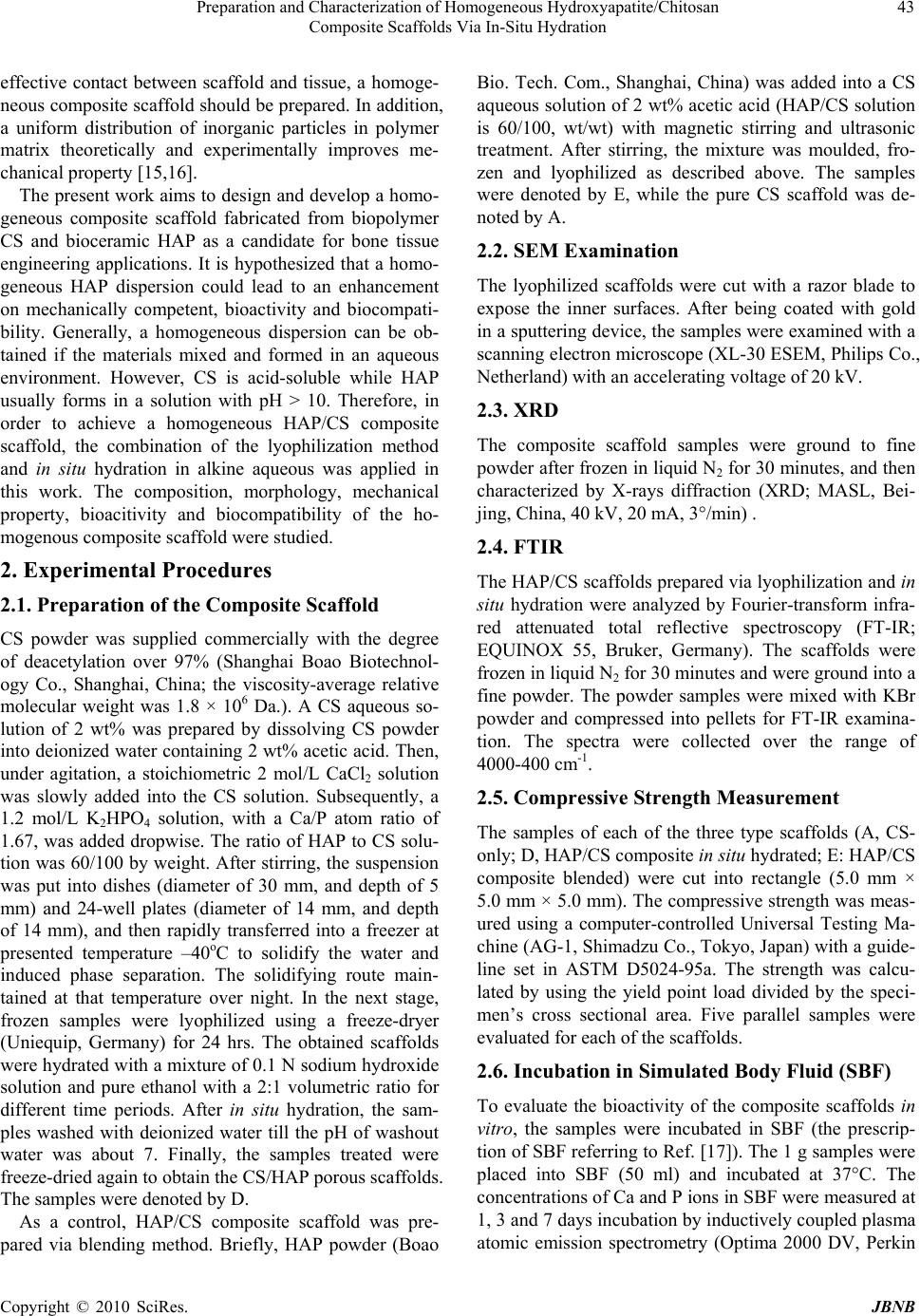 Preparation and Characterization of Homogeneous Hydroxyapatite/Chitosan 43 Composite Scaffolds Via In-Situ Hydration effective contact between scaffold and tissue, a homoge- neous composite scaffold should be prepared. In addition, a uniform distribution of inorganic particles in polymer matrix theoretically and experimentally improves me- chanical property [15,16]. The present work aims to design and develop a homo- geneous composite scaffold fabricated from biopolymer CS and bioceramic HAP as a candidate for bone tissue engineering applications. It is hypothesized that a homo- geneous HAP dispersion could lead to an enhancement on mechanically competent, bioactivity and biocompati- bility. Generally, a homogeneous dispersion can be ob- tained if the materials mixed and formed in an aqueous environment. However, CS is acid-soluble while HAP usually forms in a solution with pH > 10. Therefore, in order to achieve a homogeneous HAP/CS composite scaffold, the combination of the lyophilization method and in situ hydration in alkine aqueous was applied in this work. The composition, morphology, mechanical property, bioacitivity and biocompatibility of the ho- mogenous composite scaffold were studied. 2. Experimental Procedures 2.1. Preparation of the Composite Scaffold CS powder was supplied commercially with the degree of deacetylation over 97% (Shanghai Boao Biotechnol- ogy Co., Shanghai, China; the viscosity-average relative molecular weight was 1.8 × 10⁶ Da.). A CS aqueous so- lution of 2 wt% was prepared by dissolving CS powder into deionized water containing 2 wt% acetic acid. Then, under agitation, a stoichiometric 2 mol/L CaCl2 solution was slowly added into the CS solution. Subsequently, a 1.2 mol/L K2HPO4 solution, with a Ca/P atom ratio of 1.67, was added dropwise. The ratio of HAP to CS solu- tion was 60/100 by weight. After stirring, the suspension was put into dishes (diameter of 30 mm, and depth of 5 mm) and 24-well plates (diameter of 14 mm, and depth of 14 mm), and then rapidly transferred into a freezer at presented temperature –40oC to solidify the water and induced phase separation. The solidifying route main- tained at that temperature over night. In the next stage, frozen samples were lyophilized using a freeze-dryer (Uniequip, Germany) for 24 hrs. The obtained scaffolds were hydrated with a mixture of 0.1 N sodium hydroxide solution and pure ethanol with a 2:1 volumetric ratio for different time periods. After in situ hydration, the sam- ples washed with deionized water till the pH of washout water was about 7. Finally, the samples treated were freeze-dried again to obtain the CS/HAP porous scaffolds. The samples were denoted by D. As a control, HAP/CS composite scaffold was pre- pared via blending method. Briefly, HAP powder (Boao Bio. Tech. Com., Shanghai, China) was added into a CS aqueous solution of 2 wt% acetic acid (HAP/CS solution is 60/100, wt/wt) with magnetic stirring and ultrasonic treatment. After stirring, the mixture was moulded, fro- zen and lyophilized as described above. The samples were denoted by E, while the pure CS scaffold was de- noted by A. 2.2. SEM Examination The lyophilized scaffolds were cut with a razor blade to expose the inner surfaces. After being coated with gold in a sputtering device, the samples were examined with a scanning electron microscope (XL-30 ESEM, Philips Co., Netherland) with an accelerating voltage of 20 kV. 2.3. XRD The composite scaffold samples were ground to fine powder after frozen in liquid N2 for 30 minutes, and then characterized by X-rays diffraction (XRD; MASL, Bei- jing, China, 40 kV, 20 mA, 3°/min) . 2.4. FTIR The HAP/CS scaffolds prepared via lyophilization and in situ hydration were analyzed by Fourier-transform infra- red attenuated total reflective spectroscopy (FT-IR; EQUINOX 55, Bruker, Germany). The scaffolds were frozen in liquid N2 for 30 minutes and were ground into a fine powder. The powder samples were mixed with KBr powder and compressed into pellets for FT-IR examina- tion. The spectra were collected over the range of 4000-400 cm-1. 2.5. Compressive Strength Measurement The samples of each of the three type scaffolds (A, CS- only; D, HAP/CS composite in situ hydrated; E: HAP/CS composite blended) were cut into rectangle (5.0 mm × 5.0 mm × 5.0 mm). The compressive strength was meas- ured using a computer-controlled Universal Testing Ma- chine (AG-1, Shimadzu Co., Tokyo, Japan) with a guide- line set in ASTM D5024-95a. The strength was calcu- lated by using the yield point load divided by the speci- men’s cross sectional area. Five parallel samples were evaluated for each of the scaffolds. 2.6. Incubation in Simulated Body Fluid (SBF) To evaluate the bioactivity of the composite scaffolds in vitro, the samples were incubated in SBF (the prescrip- tion of SBF referring to Ref. [17]). The 1 g samples were placed into SBF (50 ml) and incubated at 37°C. The concentrations of Ca and P ions in SBF were measured at 1, 3 and 7 days incubation by inductively coupled plasma atomic emission spectrometry (Optima 2000 DV, Perkin Copyright © 2010 SciRes. JBNB 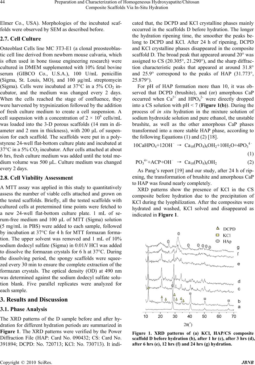 Preparation and Characterization of Homogeneous Hydroxyapatite/Chitosan 44 Composite Scaffolds Via In-Situ Hydration Elmer Co., USA). Morphologies of the incubated scaf- folds were observed by SEM as described before. 2.7. Cell Culture Osteoblast Cells line MC 3T3-E1 (a clonal preosteoblas- tic cell line derived from newborn mouse calvaria, which is often used in bone tissue engineering research) were cultured in DMEM supplemented with 10% fetal bovine serum (GIBCO Co., U.S.A.), 100 U/mL penicillin (Sigma, St. Louis, MO), and 100 μg/mL streptomycin (Sigma). Cells were incubated at 37°C in a 5% CO2 in- cubator, and the medium was changed every 2 days. When the cells reached the stage of confluence, they were harvested by trypsinization followed by the addition of fresh culture medium to create a cell suspension. A cell suspension with a concentration of 2 × 10⁶ cells/mL was loaded into the 3-D porous scaffolds (14 mm in di- ameter and 2 mm in thickness), with 200 μL of suspen- sion for each scaffold. The scaffolds were put in a poly- styrene 24-well flat-bottom culture plate and incubated at 37°C in a 5% CO2 incubator. After cells attached at about 6 hrs, fresh culture medium was added until the total me- dium volume was 500 μL. Culture medium was changed every 2 days. 2.8. Cell Viability Assessment A MTT assay was applied in this study to quantitatively assess the number of viable cells attached and grown on the tested scaffolds. Briefly, all the tested scaffolds with cultured cells at pretermined time points were fetched to a new 24-well flat-bottom culture plate. 1 mL of se- rum-free medium and 100 μL of MTT (Sigma) solution (5 mg/mL in PBS) were added to each sample, followed by incubation at 37°C for 4 h for MTT formazan forma- tion. The upper solvent was removed and 1 mL of 10% sodium dodecyl sulfate (Sigma) in 0.01N HCl was added to dissolve the formazan crystals for 6 h at 37°C. During the dissolving period, the spongy scaffolds were squee- zed every 30 min to ensure the complete extraction of the formazan crystals. The optical density (OD) at 490 nm was determined against the sodium dodecyl sulfate solu- tion blank. Five parallel replicates were analyzed for each sample. 3. Results and Discussion 3.1. Phase Analysis The XRD patterns of the D sample before and after hy- dration for different hydration periods are summarized in Figure 1. The XRD patterns were verified by the Power Diffraction File (HAP: Card No. 090432; CS: Card No. 391894; DCPD: No. 720713; KCl: No. 730713). It indi- cated that, the DCPD and KCl crystalline phases mainly occurred in the scaffolds D before hydration. The longer the hydration ripening time, the smoother the peaks be- long to DCPD and KCl. After 24 h of ripening, DCPD and KCl crystalline phases disappeared in the composite scaffold D. The broad peak that appeared around 20° was assigned to CS (20.305°, 21.290°), and the sharp diffrac- tion characteristic peaks that appeared at around 31.8° and 25.9° correspond to the peaks of HAP (31.773°, 25.879°). For pH of HAP formation more than 10, it was ob- served that DCPD (brushite), and (or) amorphous CaP occurred when Ca2+ and HPO4 2- were directly dropped into a CS solution with pH < 7 (Figure 1(b)). During the process of in situ hydration in the mixture solution of sodium hydroxide solution and pure ethanol, the unstable brushite, as well as the other amorphous CaP phases transformed into a more stable HAP phase, according to the following Equations (1) and (2) [18]. 10CaHPO4+12OH– → Ca10(PO4)6OH2+10H2O+4PO3 4– (1) PO3 4++ACP+OH– → Ca10(PO4)6OH2 (2) As Pang’s report [19] and our study, after 24 h of rip- ening, the transformation of brushite and amorphous CaP to HAP was found nearly completely. XRD patterns show the presence of KCl in the CS composite before hydration due to the precipitation of KCl during the lyophilization. After the composites were hydrated and washed, KCl solved and disappeared as indicated in Figure 1. Figure 1. XRD patterns of (a) KCl, HAP/CS composite scaffold D before hydration (b), after 1 hr (c), after 3 hrs (d), after 6 hrs (e), 12 hrs (f) and 24 hrs (g) hydration. Copyright © 2010 SciRes. JBNB 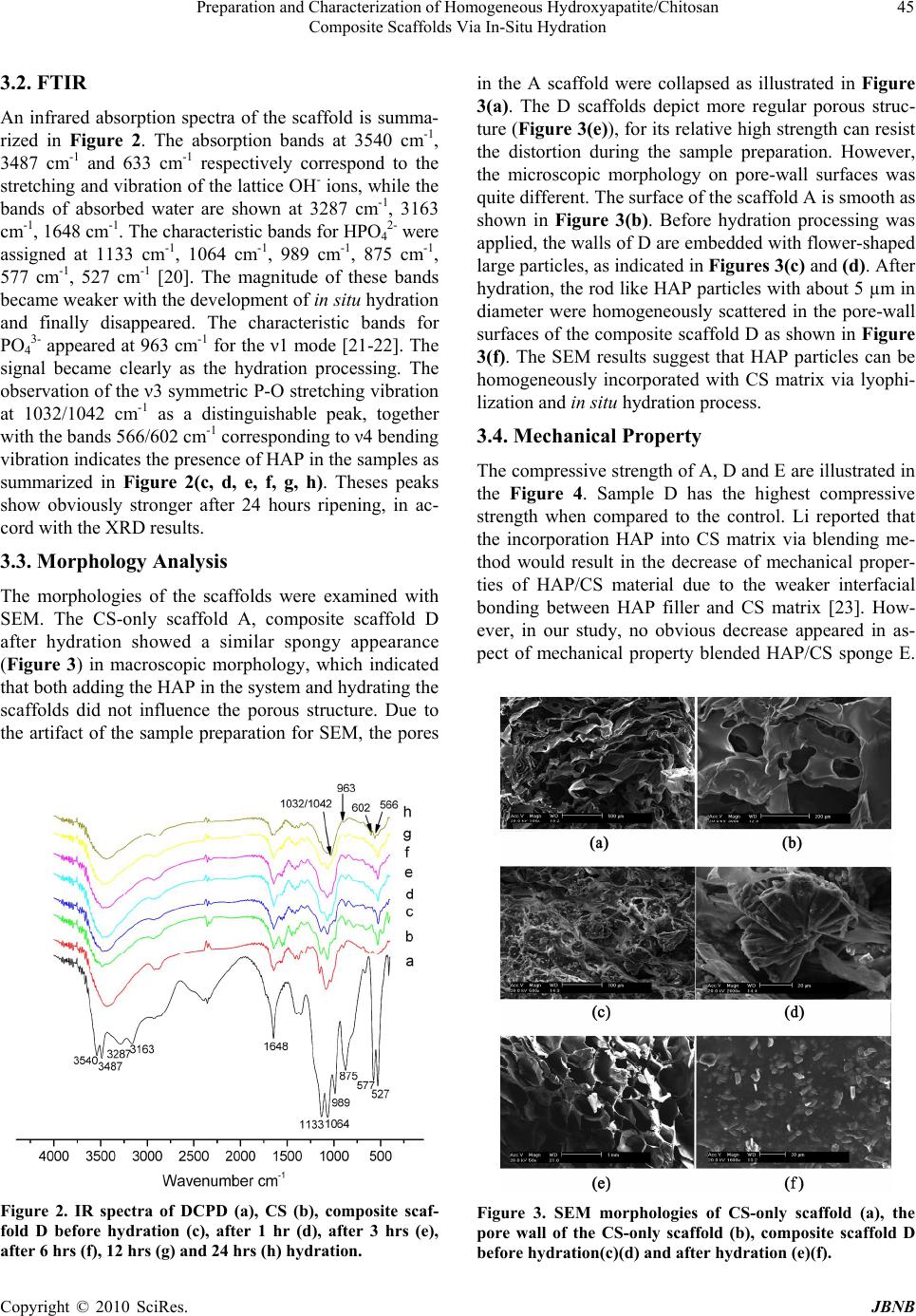 Preparation and Characterization of Homogeneous Hydroxyapatite/Chitosan 45 Composite Scaffolds Via In-Situ Hydration 3.2. FTIR An infrared absorption spectra of the scaffold is summa- rized in Figure 2. The absorption bands at 3540 cm-1, 3487 cm-1 and 633 cm-1 respectively correspond to the stretching and vibration of the lattice OH- ions, while the bands of absorbed water are shown at 3287 cm-1, 3163 cm-1, 1648 cm-1. The characteristic bands for HPO4 2- were assigned at 1133 cm-1, 1064 cm-1, 989 cm-1, 875 cm-1, 577 cm-1, 527 cm-1 [20]. The magnitude of these bands became weaker with the development of in situ hydration and finally disappeared. The characteristic bands for PO4 3- appeared at 963 cm-1 for the ν1 mode [21-22]. The signal became clearly as the hydration processing. The observation of the ν3 symmetric P-O stretching vibration at 1032/1042 cm-1 as a distinguishable peak, together with the bands 566/602 cm-1 corresponding to ν4 bending vibration indicates the presence of HAP in the samples as summarized in Figure 2(c, d, e, f, g, h). Theses peaks show obviously stronger after 24 hours ripening, in ac- cord with the XRD results. 3.3. Morphology Analysis The morphologies of the scaffolds were examined with SEM. The CS-only scaffold A, composite scaffold D after hydration showed a similar spongy appearance (Figure 3) in macroscopic morphology, which indicated that both adding the HAP in the system and hydrating the scaffolds did not influence the porous structure. Due to the artifact of the sample preparation for SEM, the pores Figure 2. IR spectra of DCPD (a), CS (b), composite scaf- fold D before hydration (c), after 1 hr (d), after 3 hrs (e), after 6 hrs (f), 12 hrs (g) and 24 hr s (h) hydration. in the A scaffold were collapsed as illustrated in Figure 3(a). The D scaffolds depict more regular porous struc- ture (Figure 3(e)), for its relative high strength can resist the distortion during the sample preparation. However, the microscopic morphology on pore-wall surfaces was quite different. The surface of the scaffold A is smooth as shown in Figure 3(b). Before hydration processing was applied, the walls of D are embedded with flower-shaped large particles, as indicated in Figures 3(c) and (d). After hydration, the rod like HAP particles with about 5 µm in diameter were homogeneously scattered in the pore-wall surfaces of the composite scaffold D as shown in Figure 3(f). The SEM results suggest that HAP particles can be homogeneously incorporated with CS matrix via lyophi- lization and in situ hydration process. 3.4. Mechanical Property The compressive strength of A, D and E are illustrated in the Figure 4. Sample D has the highest compressive strength when compared to the control. Li reported that the incorporation HAP into CS matrix via blending me- thod would result in the decrease of mechanical proper- ties of HAP/CS material due to the weaker interfacial bonding between HAP filler and CS matrix [23]. How- ever, in our study, no obvious decrease appeared in as- pect of mechanical property blended HAP/CS sponge E. Figure 3. SEM morphologies of CS-only scaffold (a), the pore wall of the CS-only scaffold (b), composite scaffold D before hydration(c)(d) and after hydration (e)(f). Copyright © 2010 SciRes. JBNB 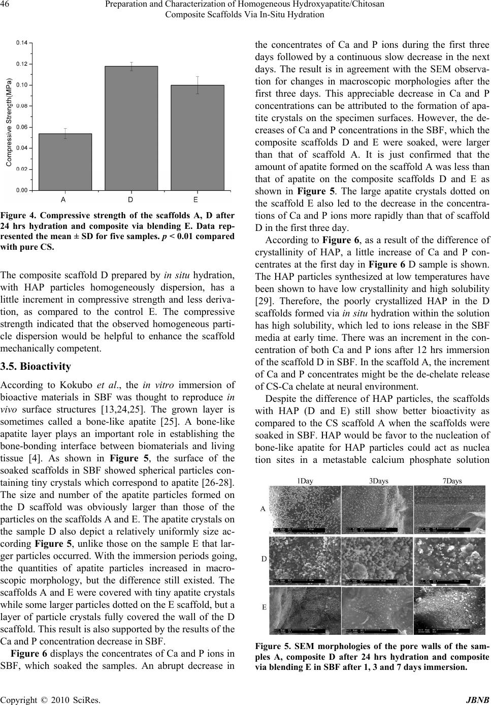 Preparation and Characterization of Homogeneous Hydroxyapatite/Chitosan 46 Composite Scaffolds Via In-Situ Hydration Figure 4. Compressive strength of the scaffolds A, D after 24 hrs hydration and composite via blending E. Data rep- resented the mean ± SD for five samples. p < 0.01 compared with pure CS. The composite scaffold D prepared by in situ hydration, with HAP particles homogeneously dispersion, has a little increment in compressive strength and less deriva- tion, as compared to the control E. The compressive strength indicated that the observed homogeneous parti- cle dispersion would be helpful to enhance the scaffold mechanically competent. 3.5. Bioactivity According to Kokubo et al., the in vitro immersion of bioactive materials in SBF was thought to reproduce in vivo surface structures [13,24,25]. The grown layer is sometimes called a bone-like apatite [25]. A bone-like apatite layer plays an important role in establishing the bone-bonding interface between biomaterials and living tissue [4]. As shown in Figure 5, the surface of the soaked scaffolds in SBF showed spherical particles con- taining tiny crystals which correspond to apatite [26-28]. The size and number of the apatite particles formed on the D scaffold was obviously larger than those of the particles on the scaffolds A and E. The apatite crystals on the sample D also depict a relatively uniformly size ac- cording Figure 5, unlike those on the sample E that lar- ger particles occurred. With the immersion periods going, the quantities of apatite particles increased in macro- scopic morphology, but the difference still existed. The scaffolds A and E were covered with tiny apatite crystals while some larger particles dotted on the E scaffold, but a layer of particle crystals fully covered the wall of the D scaffold. This result is also supported by the results of the Ca and P concentration decrease in SBF. Figure 6 displays the concentrates of Ca and P ions in SBF, which soaked the samples. An abrupt decrease in the concentrates of Ca and P ions during the first three days followed by a continuous slow decrease in the next days. The result is in agreement with the SEM observa- tion for changes in macroscopic morphologies after the first three days. This appreciable decrease in Ca and P concentrations can be attributed to the formation of apa- tite crystals on the specimen surfaces. However, the de- creases of Ca and P concentrations in the SBF, which the composite scaffolds D and E were soaked, were larger than that of scaffold A. It is just confirmed that the amount of apatite formed on the scaffold A was less than that of apatite on the composite scaffolds D and E as shown in Figure 5. The large apatite crystals dotted on the scaffold E also led to the decrease in the concentra- tions of Ca and P ions more rapidly than that of scaffold D in the first three day. According to Figure 6, as a result of the difference of crystallinity of HAP, a little increase of Ca and P con- centrates at the first day in Figure 6 D sample is shown. The HAP particles synthesized at low temperatures have been shown to have low crystallinity and high solubility [29]. Therefore, the poorly crystallized HAP in the D scaffolds formed via in situ hydration within the solution has high solubility, which led to ions release in the SBF media at early time. There was an increment in the con- centration of both Ca and P ions after 12 hrs immersion of the scaffold D in SBF. In the scaffold A, the increment of Ca and P concentrates might be the de-chelate release of CS-Ca chelate at neural environment. Despite the difference of HAP particles, the scaffolds with HAP (D and E) still show better bioactivity as compared to the CS scaffold A when the scaffolds were soaked in SBF. HAP would be favor to the nucleation of bone-like apatite for HAP particles could act as nuclea tion sites in a metastable calcium phosphate solution Figure 5. SEM morphologies of the pore walls of the sam- ples A, composite D after 24 hrs hydration and composite via blending E in SBF after 1, 3 and 7 days immersion. Copyright © 2010 SciRes. JBNB 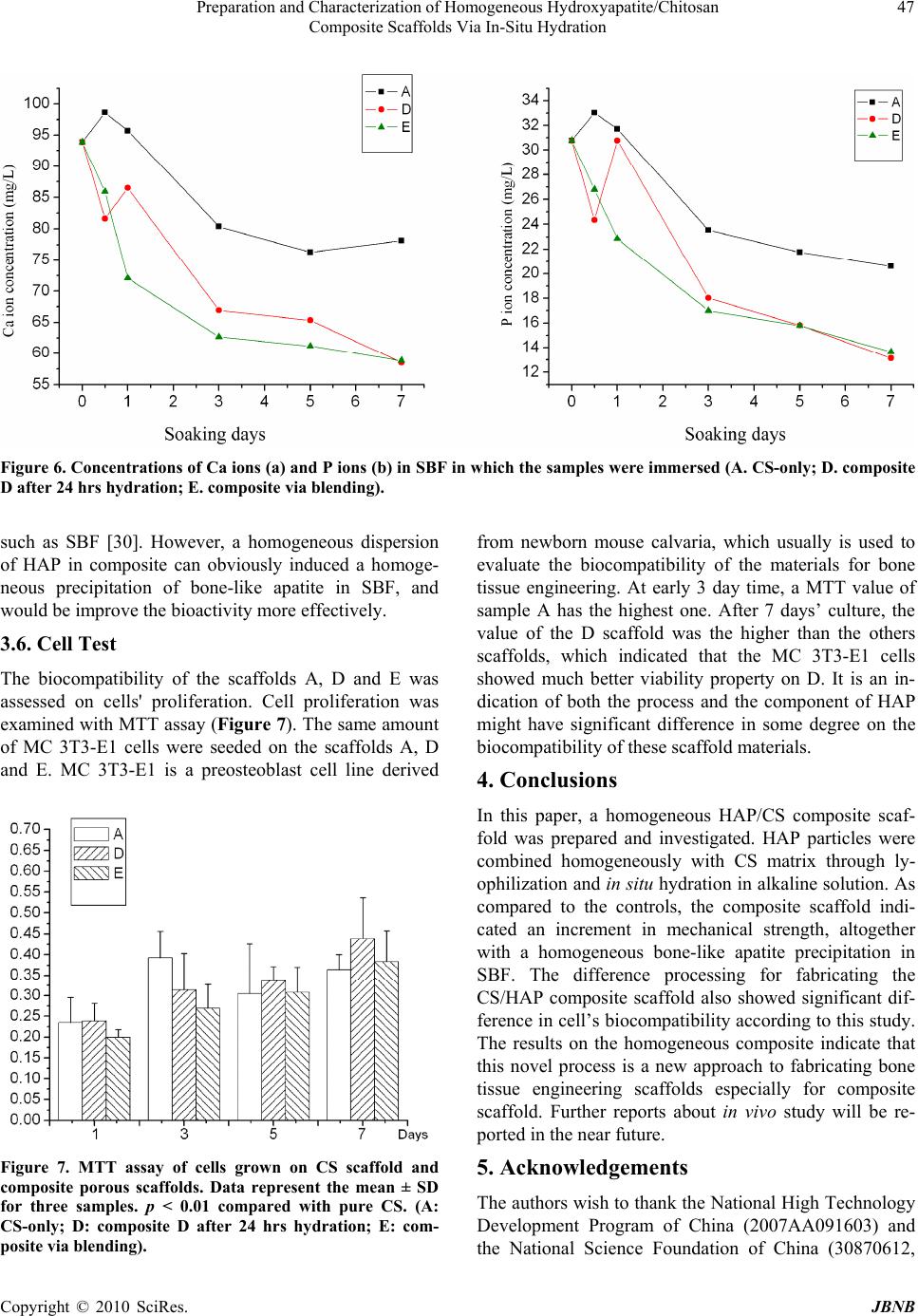 Preparation and Characterization of Homogeneous Hydroxyapatite/Chitosan Composite Scaffolds Via In-Situ Hydration Copyright © 2010 SciRes. JBNB 47 Figure 6. Concentrations of Ca ions (a) and P ions (b) in SBF in which the samples were immersed (A. CS-only; D. composite D after 24 hrs hydration; E. composite via blending). such as SBF [30]. However, a homogeneous dispersion of HAP in composite can obviously induced a homoge- neous precipitation of bone-like apatite in SBF, and would be improve the bioactivity more effectively. from newborn mouse calvaria, which usually is used to evaluate the biocompatibility of the materials for bone tissue engineering. At early 3 day time, a MTT value of sample A has the highest one. After 7 days’ culture, the value of the D scaffold was the higher than the others scaffolds, which indicated that the MC 3T3-E1 cells showed much better viability property on D. It is an in- dication of both the process and the component of HAP might have significant difference in some degree on the biocompatibility of these scaffold materials. 3.6. Cell Test The biocompatibility of the scaffolds A, D and E was assessed on cells' proliferation. Cell proliferation was examined with MTT assay (Figure 7). The same amount of MC 3T3-E1 cells were seeded on the scaffolds A, D and E. MC 3T3-E1 is a preosteoblast cell line derived 4. Conclusions In this paper, a homogeneous HAP/CS composite scaf- fold was prepared and investigated. HAP particles were combined homogeneously with CS matrix through ly- ophilization and in situ hydration in alkaline solution. As compared to the controls, the composite scaffold indi- cated an increment in mechanical strength, altogether with a homogeneous bone-like apatite precipitation in SBF. The difference processing for fabricating the CS/HAP composite scaffold also showed significant dif- ference in cell’s biocompatibility according to this study. The results on the homogeneous composite indicate that this novel process is a new approach to fabricating bone tissue engineering scaffolds especially for composite scaffold. Further reports about in vivo study will be re- ported in the near future. 5. Acknowledgements Figure 7. MTT assay of cells grown on CS scaffold and composite porous scaffolds. Data represent the mean ± SD for three samples. p < 0.01 compared with pure CS. (A: CS-only; D: composite D after 24 hrs hydration; E: com- posite via blending). The authors wish to thank the National High Technology Development Program of China (2007AA091603) and the National Science Foundation of China (30870612, 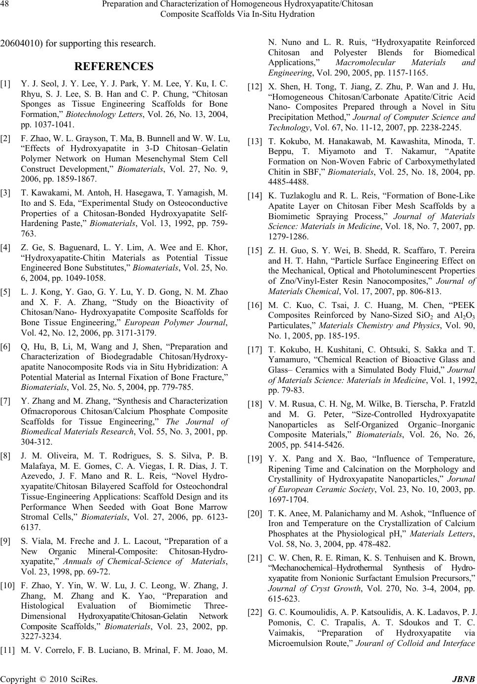 Preparation and Characterization of Homogeneous Hydroxyapatite/Chitosan 48 Composite Scaffolds Via In-Situ Hydration 20604010) for supporting this research. REFERENCES [1] Y. J. Seol, J. Y. Lee, Y. J. Park, Y. M. Lee, Y. Ku, I. C. Rhyu, S. J. Lee, S. B. Han and C. P. Chung, “Chitosan Sponges as Tissue Engineering Scaffolds for Bone Formation,” Biotechnology Letters, Vol. 26, No. 13, 2004, pp. 1037-1041. [2] F. Zhao, W. L. Grayson, T. Ma, B. Bunnell and W. W. Lu, “Effects of Hydroxyapatite in 3-D Chitosan–Gelatin Polymer Network on Human Mesenchymal Stem Cell Construct Development,” Biomaterials, Vol. 27, No. 9, 2006, pp. 1859-1867. [3] T. Kawakami, M. Antoh, H. Hasegawa, T. Yamagish, M. Ito and S. Eda, “Experimental Study on Osteoconductive Properties of a Chitosan-Bonded Hydroxyapatite Self- Hardening Paste,” Biomaterials, Vol. 13, 1992, pp. 759- 763. [4] Z. Ge, S. Baguenard, L. Y. Lim, A. Wee and E. Khor, “Hydroxyapatite-Chitin Materials as Potential Tissue Engineered Bone Substitutes,” Biomaterials, Vol. 25, No. 6, 2004, pp. 1049-1058. [5] L. J. Kong, Y. Gao, G. Y. Lu, Y. D. Gong, N. M. Zhao and X. F. A. Zhang, “Study on the Bioactivity of Chitosan/Nano- Hydroxyapatite Composite Scaffolds for Bone Tissue Engineering,” European Polymer Journal, Vol. 42, No. 12, 2006, pp. 3171-3179. [6] Q, Hu, B, Li, M, Wang and J, Shen, “Preparation and Characterization of Biodegradable Chitosan/Hydroxy- apatite Nanocomposite Rods via in Situ Hybridization: A Potential Material as Internal Fixation of Bone Fracture,” Biomaterials, Vol. 25, No. 5, 2004, pp. 779-785. [7] Y. Zhang and M. Zhang, “Synthesis and Characterization Ofmacroporous Chitosan/Calcium Phosphate Composite Scaffolds for Tissue Engineering,” The Journal of Biomedical Materials Research, Vol. 55, No. 3, 2001, pp. 304-312. [8] J. M. Oliveira, M. T. Rodrigues, S. S. Silva, P. B. Malafaya, M. E. Gomes, C. A. Viegas, I. R. Dias, J. T. Azevedo, J. F. Mano and R. L. Reis, “Novel Hydro- xyapatite/Chitosan Bilayered Scaffold for Osteochondral Tissue-Engineering Applications: Scaffold Design and its Performance When Seeded with Goat Bone Marrow Stromal Cells,” Biomaterials, Vol. 27, 2006, pp. 6123- 6137. [9] S. Viala, M. Freche and J. L. Lacout, “Preparation of a New Organic Mineral-Composite: Chitosan-Hydro- xyapatite,” Annuals of Chemical-Science of Materials, Vol. 23, 1998, pp. 69-72. [10] F. Zhao, Y. Yin, W. W. Lu, J. C. Leong, W. Zhang, J. Zhang, M. Zhang and K. Yao, “Preparation and Histological Evaluation of Biomimetic Three- Dimensional Hydroxyapatite/Chitosan-Gelatin Network Composite Scaffolds,” Biomaterials, Vol. 23, 2002, pp. 3227-3234. [11] M. V. Correlo, F. B. Luciano, B. Mrinal, F. M. Joao, M. N. Nuno and L. R. Ruis, “Hydroxyapatite Reinforced Chitosan and Polyester Blends for Biomedical Applications,” Macromolecular Materials and Engineering, Vol. 290, 2005, pp. 1157-1165. [12] X. Shen, H. Tong, T. Jiang, Z. Zhu, P. Wan and J. Hu, “Homogeneous Chitosan/Carbonate Apatite/Citric Acid Nano- Composites Prepared through a Novel in Situ Precipitation Method,” Journal of Computer Science and Technology, Vol. 67, No. 11-12, 2007, pp. 2238-2245. [13] T. Kokubo, M. Hanakawab, M. Kawashita, Minoda, T. Beppu, T. Miyamoto and T. Nakamur, “Apatite Formation on Non-Woven Fabric of Carboxymethylated Chitin in SBF,” Biomaterials, Vol. 25, No. 18, 2004, pp. 4485-4488. [14] K. Tuzlakoglu and R. L. Reis, “Formation of Bone-Like Apatite Layer on Chitosan Fiber Mesh Scaffolds by a Biomimetic Spraying Process,” Journal of Materials Science: Materials in Medicine, Vol. 18, No. 7, 2007, pp. 1279-1286. [15] Z. H. Guo, S. Y. Wei, B. Shedd, R. Scaffaro, T. Pereira and H. T. Hahn, “Particle Surface Engineering Effect on the Mechanical, Optical and Photoluminescent Properties of Zno/Vinyl-Ester Resin Nanocomposites,” Journal of Materials Chemical, Vol. 17, 2007, pp. 806-813. [16] M. C. Kuo, C. Tsai, J. C. Huang, M. Chen, “PEEK Composites Reinforced by Nano-Sized SiO2 and Al2O3 Particulates,” Materials Chemistry and Physics, Vol. 90, No. 1, 2005, pp. 185-195. [17] T. Kokubo, H. Kushitani, C. Ohtsuki, S. Sakka and T. Yamamuro, “Chemical Reaction of Bioactive Glass and Glass– Ceramics with a Simulated Body Fluid,” Journal of Materials Science: Materials in Medicine, Vol. 1, 1992, pp. 79-83. [18] V. M. Rusua, C. H. Ng, M. Wilke, B. Tierscha, P. Fratzld and M. G. Peter, “Size-Controlled Hydroxyapatite Nanoparticles as Self-Organized Organic–Inorganic Composite Materials,” Biomaterials, Vol. 26, No. 26, 2005, pp. 5414-5426. [19] Y. X. Pang and X. Bao, “Influence of Temperature, Ripening Time and Calcination on the Morphology and Crystallinity of Hydroxyapatite Nanoparticles,” Jorunal of European Ceramic Society, Vol. 23, No. 10, 2003, pp. 1697-1704. [20] T. K. Anee, M. Palanichamy and M. Ashok, “Influence of Iron and Temperature on the Crystallization of Calcium Phosphates at the Physiological pH,” Materials Letters, Vol. 58, No. 3, 2004, pp. 478-482. [21] C. W. Chen, R. E. Riman, K. S. Tenhuisen and K. Brown, “Mechanochemical–Hydrothermal Synthesis of Hydro- xyapatite from Nonionic Surfactant Emulsion Precursors,” Journal of Cryst Growth, Vol. 270, No. 3-4, 2004, pp. 615-623. [22] G. C. Koumoulidis, A. P. Katsoulidis, A. K. Ladavos, P. J. Pomonis, C. C. Trapalis, A. T. Sdoukos and T. C. Vaimakis, “Preparation of Hydroxyapatite via Microemulsion Route,” Jouranl of Colloid and Interface Copyright © 2010 SciRes. JBNB  Preparation and Characterization of Homogeneous Hydroxyapatite/Chitosan Composite Scaffolds Via In-Situ Hydration Copyright © 2010 SciRes. JBNB 49 Science, Vol. 259, 2003, pp. 254-260. [23] B. Q. Li, Q. L. Hu, X. Z. Qian, Z. P. Fang and J. C. Shen, “Bioabsorbable Chitosan/Hydroxyapatite Composite Rod for Internal Fixation of Bone Fracture Prepared by in Situ Precipitation,” Acta Polymerica Sinica, Vol. 6, 2002, pp. 828-833. [24] T. Kokubo, I. Ito and T. Huang, “P–Rich Layer Formed on High–Strength Bioactive Glass–Ceramics A–W,” Journal of Biomedical Materials Research, Vol. 24, 1990, pp. 331- 343. [25] P. Li, C. Ohtsukl and T. Kokubo, “Effects of Ions in Aqueous Media on Hydroxyapatite Induction by Silica Gel and Its Relevance to Bioactivity of Bioactive Glasses and Glass/ Ceramics,” Journal of Applied Biomaterials, Vol. 4, 1993, No. 3, pp. 221-229. [26] A. S. Posner, “The Mineral of Bone,” Clinical Orthopaedics Related Research, Vol. 200, 1985, pp. 87-93. [27] T. Kokubo, “Apatite Formation on Surfaces of Ceramics, Metals and Polymers in Body Environment,” Acta Materialia, Vol. 46, No. 7, 1998, pp. 2519-2527. [28] X. Lu and Y. Leng, “Thyeoretical Analysis of Calcium Phosphate Precipitation in Simulated Body Fluid,” Biomaterials, Vol. 26, No. 10, 2005, 1097-1108. [29] T. Matsumoto, M. Okazaki, M. Inoue, S. Yamaguchi, T. Kusunose, T. Toyonaga, Y. Hamada and J. Takahashi, “Hydroxyapatite Particles as a Controlled Release Carrier of Protein,” Biomaterials, Vol. 25, No. 17, 2004, pp. 3807-3812. [30] T. Kokubo, “Apatite Formation on Surfaces of Ceramics, Metals and Polymers in Body Environment,” Acta Materialia, Vol. 46, No. 7, 1998, pp. 2519-2527. |