Open Journal of Fluid Dynamics
Vol.2 No.4A(2012), Article ID:26372,5 pages DOI:10.4236/ojfd.2012.24A048
Performances and Rotating Flows of Rotary Jet Pump
1Graduate School of Engineering, Kyushu Institute of Technology, Kitakyushu, Japan
2Faculty of Engineering, Kyushu Institute of Technology, Kitakyushu, Japan
Email: m344121k@tobata.isc.kyutech.ac.jp
Received October 4, 2012; revised November 16, 2012; accepted November 28, 2012
Keywords: Rotation Casing Type Pump; Pitot Pump; High Pressure Pump; Pick-Up Tube; Forced Vortex; Secondary Flow
ABSTRACT
The rotary jet pumps, namely the pitot pumps, are composed of the rotating casing with the impeller channels and the stationary pick-up tube for discharging, are known as the one of high pressure pumps in the U.S. market. The pumps, however, have been prepared experientially, because of poor knowledge for the flow conditions and the pump performances. Then, this paper discusses the pump performances and the internal flow conditions in the rotating casing. Three types of the pick-up tube were prepared for the experiments to know the pump performances and the flow conditions in the rotating casing. The flow in the rotating casing is nearly in the forced vortex type and gives the higher pressure at the pick-up tube inlet. The more cross-sectional area of the pick-up tube channel is large, the more head and discharge are higher with excellent efficiency. Moreover, the authors confirmed that the secondary flow runs toward the rotating center at the wake flow region behind the pick-up tube.
1. Introduction
Recently, it is compelling social problems, for developing countries with population growths and economic growths to save energy. The turbo pumps are demanded for pump performance improvement and/or energy saving. The authors focus attention on the rotary jet pump (sometimes called RJ pump) which is also known as the rotation casing type pump or the pitot pump [1], in place of the traditional type multistage pumps. As main applications, RJ pump is popular as the high pressure pump for boiler feed systems, cleaning of machined die-casting, welding machine cooling, etc. in Japan, not to mention the United States. However, RJ pump has serious problems to get the head and discharge with the higher efficiency, contrary to have many advantages such as few parts and easy maintenance. In the past reports, the interaction between the rotating casing and the stationary pick-up tube, namely the discharge tube [2], the reduction of the friction loss in the pick-up tube channel [3], the modifications of the pick-up tube inlet profile form [4] have been investigated. However, the relation between the pump performances and the internal flow conditions has been out of the investigations.
On such poor technologies, this paper experimentally investigated and discussed the pump performances and the flow conditions in the rotating casing, as the preparation to get not only higher head but also the higher discharge with the higher efficiency.
2. Model Pump and Experiments
2.1. Model Pump
The general-purpose RJ pump shown in Figure 1 is composed of the rotating casing with the impeller channels (impeller of number is 10), the stationary suction cover supported by the outer casing and the stationary pick-up tube for discharging. The pick-up tube inlet is closed to the maximum inner diameter of the rotating casing. The fluids velocity against the inlet of the pick-up tube is almost the same as the rotational speed of the casing. That is, the pumping work quite differs from one of the traditional type pumps where the impeller gives the hydraulic power.
2.2. Experimental Setup
The experimental system is shown in Figure 2. The suction and the discharge pipes with the gate valves of the model pump are connected to the reserve tank, and discharge pipe equips with the electromagnetic flow meter. In the performance test, the flow rate is changed at the gate valve with discharge pipe and measured by electromagnetic flow meter. The pump head H is estimated with the static and dynamic pressure at the pump suction and discharge pressure tap, and the input power P are estimated with the rotational torque T and rotational speed n. The rotational speed is kept constant an inverter.
2.3. Model Pick-Up Tube
The model pick-up tubes prepared in this experiment are shown in Figure 3. The tube profiles are discerned with the width w1 and w2 at the specified radius at r = 0.57LD (LD: the tube height). 0.57LD is the position tube width w1 and w2 become constant. The three type tube dimensions are shown in Table 1. Tube M is original type. The dimensions of Tube S and Tube L are smaller and larger than the dimensions of Tube M. The three type tubes exterior are the streamline shape to reduce the drag force of the tube. And the cross-sectional area of the tube passage is nearly in proportion to the dimensions (Table 1). In this experiment, in order to investigate the wake flow conditions of the pick-up tube, 3 holes pitot tube is installed on the model pick-up tube so that it can measure the position of broken line (see Figure 3). 3 holes pitot tube can measure the circumferential velocity and radial velocity of the fluids.
2.4. Measurement of the Pressure on the Rotating Wall
It is very important to know the pressure on the rotating wall of the RJ pump. The rotating wall pressure measurement system is shown in Figure 4. The rotating casing has the conduit transmitting the pressure from the tap at the wall to the center of the rotating casing. The conduit is connected to another conduit drilled in the main shaft with the flexible tube. The shaft is surrounded with the stationary box having the hermetically-sealed chambers, and the chamber connect to the conduit of the shaft and the pressure transducer at the outside. The pressure indicated by the pressure transducer is corrected with the pressure induced from the forced vortex, to know the net pressure on the rotating wall.
3. Pump Performances
Figure 5 shows the pump performances when the pump has the Tube L, Tube M and Tube S, where  is the flow coefficient [=Q/(D3n), Q is the discharge of the pick-up tube, D is the maximum inner diameter of the rotating casing (see Figure 1), n is the rotation speed], ψ is the head coefficient [=2gH/(D2n2), H is the pump head, g is the acceleration of gravity], ν is the power coefficient [=P/(ρD5n3), P is the input power removed the mechaniccal power], η is the hydraulic efficiency [=
 /(2ν)]. All coefficients are normalized best efficiency point (the subscript 11bep) of the pump has Tube M. The circle and the square and the triangle points are results measured various rotational speed. It was confirmed that RJ pump
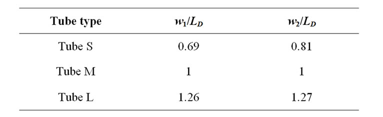
Table 1. Dimensions of the pick-up tube.
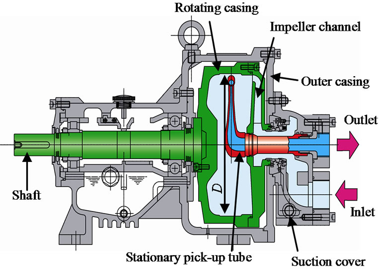
Figure 1. Meridian view of the general-purpose RJ pump.

Figure 2. Experimental set up.
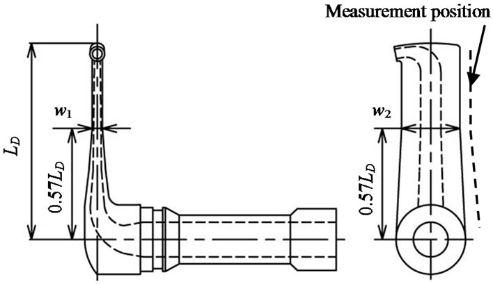
Figure 3. Model pick-up tube.
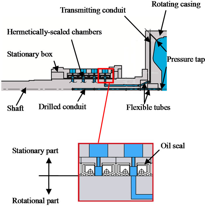
Figure 4. Extended figure of the pressure measurement system.
also satisfy the similarity law. The head decrease and the input power increase with the increase of the discharge, in similar to the performances of the centrifugal pump. With the increase of the pick-up tube dimension, the pump can be operated and takes the maximum efficiency at the higher discharge. Besides, the maximum efficiency is also higher because of the large cross-section. That is, the more cross-sectional area of the pick-up tube channel is large, the more head and discharge are higher with the excellent efficiency to decrease of the hydraulic loss.
On the other hand, the head at the shutoff operation is high when the pick-up tube is the small dimension. In the shutoff condition, the authors think that the drag force of the pick-up tube influences flow condition in the rotating casing.
4. Internal Flow
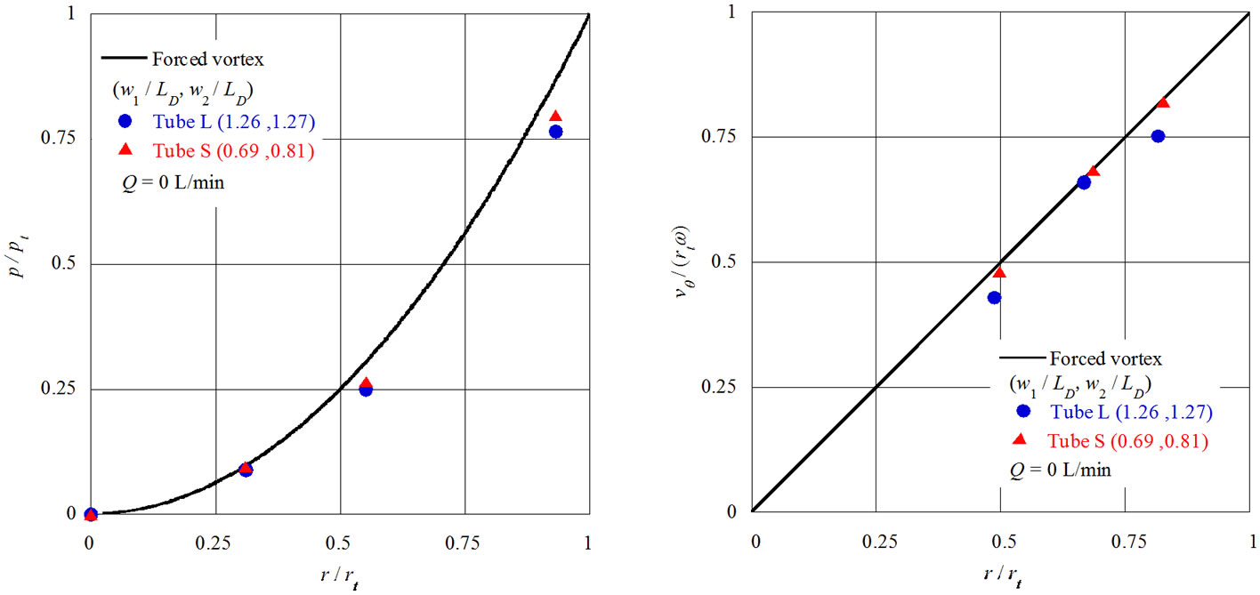
The authors experimentally investigated the static pressure p on the rotating wall and the circumferential velocity vθ in the casing in order to confirm the internal flow
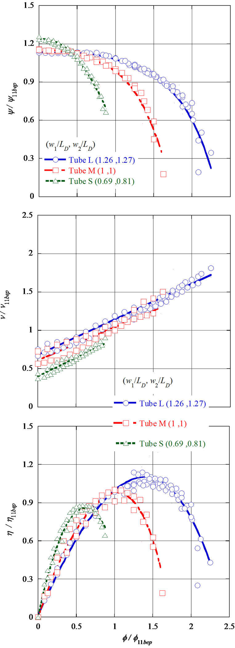
Figure 5. Pump performances.
 (a) (b)
Figure 6. Pressure and velocity distributions on the middle rotating plane.
 (a) (b)
Figure 7. Wake flow behind the pick-up tube.
conditions at shutoff condition. Figure 6 shows the investigated results, where r is the radius in the rotating casing and the subscript t means the value at the maximum radius position (the rotating wall surface). The forced vortex is the full line in Figure 6(b), and brings the pressure distribution as shown by full line in Figure 6(a), where the circle and the triangle points are the experimental results measured on the middle rotating plane at the opposite side of the pick-up tube. The experimental velocity is slightly smaller than the forced vortex due to the drag force of the pick-up tube, namely the velocity is faster while the pump equips with the smaller pick-up tube.
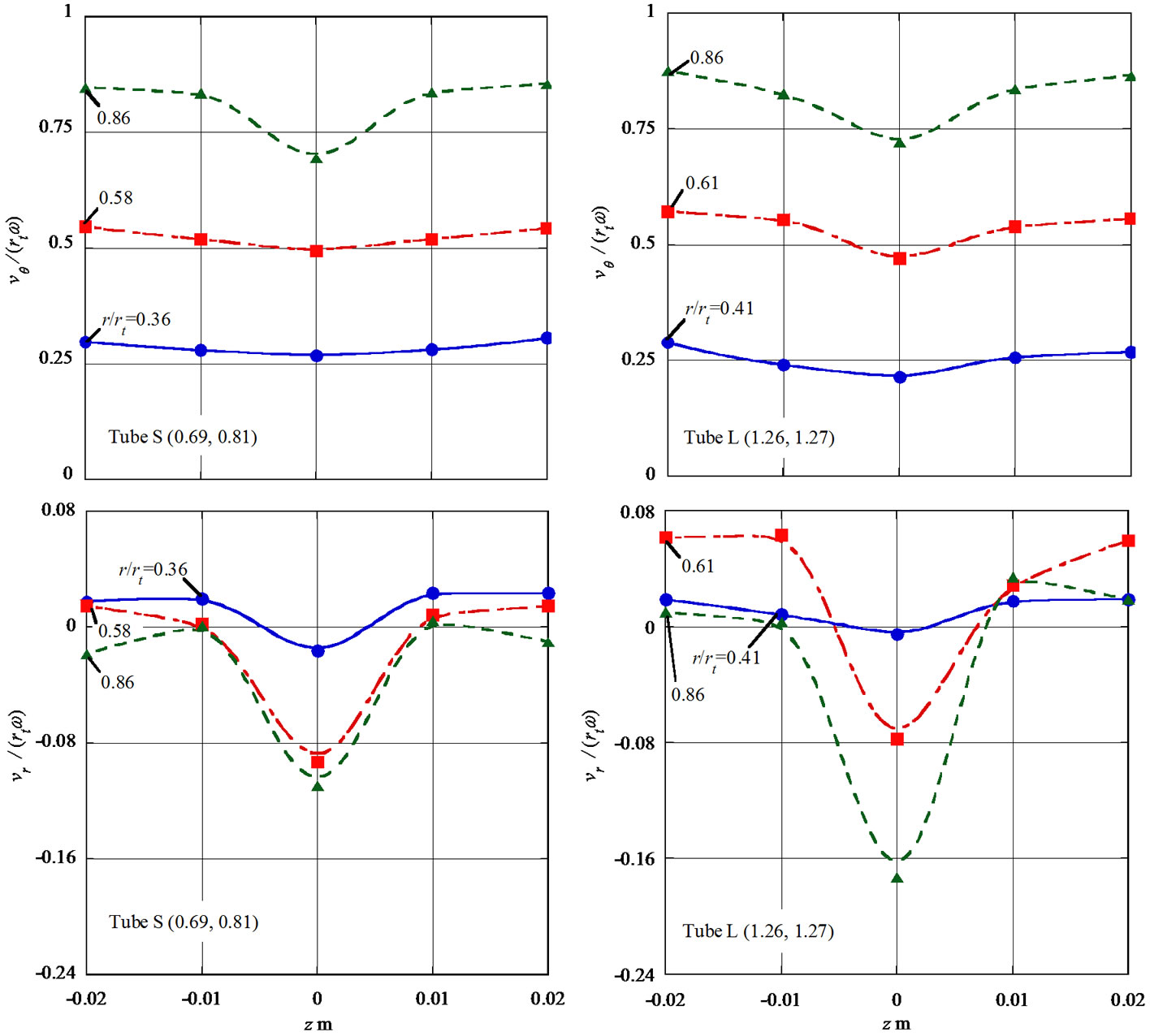
Figure 7 shows the flow condition downstream of 10 mm from the pick-up tube (see Figure 3), where vr is the radial velocity component, z is the width in the rotating casing when the origin was set as the pick-up tube center. The measurement positions are normalized r/rt = 0.36, 0.58, 0.86 with Tube S in Figure 7(a), and normalized r/rt = 0.41, 0.61, 0.86 with Tube L in Figure 7(b) at the best efficiency point. The wake flow of the pick-up tube at z = 0 mm by the circumferential velocity distribution is clearly observed. The radial velocity distributions show the negative value at the wake flow region. That is, the secondary flow region in relation to the pressure gradient and the centrifugal force.
5. Conclusion
The authors experimentally investigated and discussed the pump performances and the internal flow conditions in the rotating casing of the RJ pump to get not only the higher head but also the higher discharge with the higher efficiency.
6. Acknowledgements
The authors wish to thank HONDA KIKO CO., LTD. which provided the model pump and funds for the serial researches.
REFERENCES
- T. Ikeguchi, T. Ishibashi and S. Kawakami, “Pump Handbook,” 1st Edition, Chijinshokan Co., Ltd., Tokyo, 1982, pp. 153-154.
- Y. Tanasawa and Y. Miyasaka, “A Study on the Pitot Pump, 1st Report, On the Characteristic of Pressure Pumps,” The Japan Society of Mechanical Engineers, Vol. 15, No. 51, 1951, pp. 39-43.
- A. Kato, “Pitot Pump,” Japanese Unexamined Patent Application Publication No. Hei 6-241184, 1994.
- T. Hattori, “Structure of the Pitot Tube on the Pitot Pump,” Japanese Unexamined Patent Application Publication No. Hei 9-324785, 1997.