Journal of Electromagnetic Analysis and Applications
Vol. 5 No. 8 (2013) , Article ID: 35489 , 5 pages DOI:10.4236/jemaa.2013.58051
A Hybrid Reconfigurable Antenna Design for Cognitive Radio System
—Combination of Sensing and Reconfigurable Antennas
![]()
Electrical and Electronics Department, Al-Huson University College, Al-Balqa’ Applied University, Irbed, Jordan.Email: yahya@huson.edu.jo, nedaltaw@yahoo.com, emadg@huson.edu.jo
Copyright (c) 2013 Yahya S. H. Khraisat et al. This is an open access article distributed under the Creative Commons Attribution License, which permits unrestricted use, distribution, and reproduction in any medium, provided the original work is properly cited
Received May 13th, 2013; revised June 18th, 2013; accepted July 15th, 2013
Keywords: Reconfigurable Antenna; Sensing Antenna; Hybrid Combination; Cognitive Radio System
ABSTRACT
This paper presents a modification of an existing cognitive antenna design which contains two antennas: one is a sensing that covers the band from 1 - 11 GHz and the other is a hybrid triangular reconfigurable antenna. Two antennas are combined together to create a new design which called Cognitive Antenna. The new shape of the reconfigurable antenna will affect the cognitive antenna so as to work at two different frequencies via rotation by 180˚. At each rotation, the antenna takes single frequency from number of possible frequencies that sensing antenna would find.
1. Introduction
A cognitive radio CR is a wireless transponder that can sense the environment in which it wishes to operate and can adapt itself to optimize its operation. Sensing the environment may involve the measurement of the communications traffic and interference across a large part of the electromagnetic spectrum. The radio will also have knowledge of the intentions of its user, to enable it to match its searches to the needs of the user. In recent years, the growth of communication systems and the high demand for frequency bands have caused a perceived shortage in the available RF spectrum [1] so that a many designs of CR are created and each one surly has his advantages and disadvantages.
This design is not a new one, it is a modification of an existing one [2] to get and fabricate more efficient antenna. In this paper, a hybrid antenna structure for cognitive radio is presented. In Section II, the design of the ultra wideband (UWB) antenna for channel sensing is presented. Section III discusses the reconfigurable hybrid triangular-shaped antenna. Section IV shows the combination of two antennas (CR).
Researches in Cognitive Radio
According to the Federal Communications Commission (FCC), a cognitive radio is “a radio that can change its transmitter parameters based on interaction with the environment in which it operates”. Thus, a cognitive radio should be able to recognize spectrum availability and reconfigure itself for more efficient communications and spectrum use [3]. The monitoring of the wireless spectrum is the key in cognitive radio since the spectrum can be idle for 90% of the time. Therefore, in such a system, we should differentiate between a primary user that owns the spectrum and a secondary user that wants to access the spectrum whenever it is idle [4].
Some research has been done related to the design of antennas for cognitive radio systems. In [5], a new technique is introduced that uses a tunable narrowband planar inverted-F antenna (PIFA). In [6], two reconfigurable antenna systems, both capable of operating in five cellular radio bands, are presented. Both approaches yield overall improvements in performance and are likely to be used in cognitive radios. In [7], a combination of wideband and narrowband antennas into the same volume is presented. The wideband antenna is a coplanar waveguide (CPW)-fed printed hourglass-shaped monopole that operates from 3 - 11 GHz. The narrowband antenna is a microstrip patch printed on the reverse side of the substrate and connected to the wideband antenna via a shorting pin and designed to operate from 5.15 - 5.35 GHz. The authors in [8] discuss some of the possible antenna requirements for cognitive radio applications and outline some design approaches. Results for three antennas, suitable for small and medium-sized terminals, are given.
In our design, a new antenna structure for cognitive radio is presented; the design of the ultra wideband (UWB) antenna for channel sensing is presented; the reconfigurable hybrid triangular-shaped antenna is also presented. The final cognitive antenna design that is based on the two structures detailed is also shown.
2. Sensing Antenna Design
A sensing antenna design with wideband is necessary to be able to achieve the channel sensing and get more than one or two operating frequencies.
A structure of sensing is designed to be able to contain a reconfigurable antenna with same substrate. The chosen substrate is Rogers Duroid with dielectric constant 2.2 and height 1.6 mm also tangent loss = 0.003. All dimension are shown in the Figure 1.
All simulations were done using IE3D ver. 14. The corresponding antenna return loss is shown in Figure 2. It shows coverage from 1 - 11 GHz, making it suitable for channel sensing in cognitive radio systems. This antenna structure shows an excitation for three bands which exceed −10 db return loss (5.38, 8.44 and 10.56) GHz as shown in Figure 2. The 3D radiation pattern for the bands (5.38, 8.44 and 10.56) GHz is shown in Figures 3-
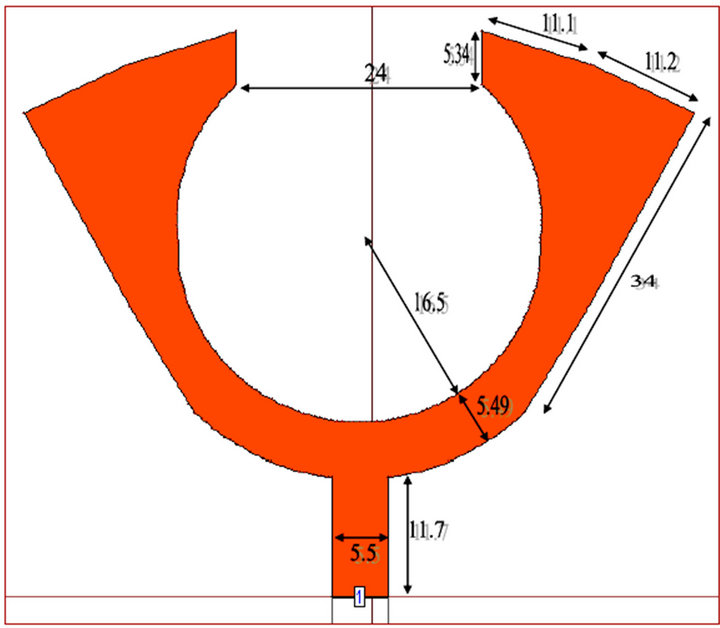
Figure 1. Sensing Antenna (all dimensions in mm).
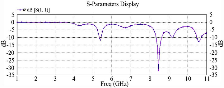
Figure 2. Return Loss of Sensing Antenna.
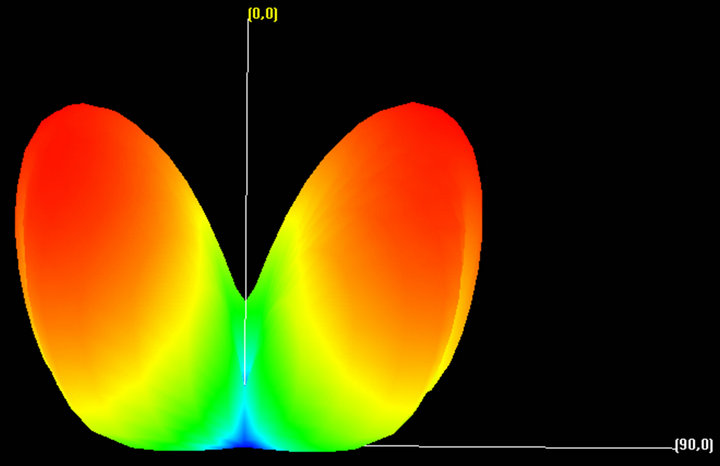
Figure 3. 3D radiation pattern for 5.38 GHz. For this band the maximum gain is 6.43 dB and the return loss is −12 dB.
5 sequentially.
The summary of sensing antenna results is shown in Table 1.
3. Reconfigurable Antenna Design
In this design, we suggest a new way to implement fre- quency reconfigurable antenna design. A rotating part (by 180˚) of the antenna is responsible to produce the required frequency tuning [9]. This rotation will produce two different resonances, each resonance will be one of the sensing result and this is the aim of tunable or reconfiguration process. The antenna layer consists of two triangular-shaped patches that are separated by a given rectangular shape and this we modified. The advantage of this modification will be shown in the last section.
As you see, this structure is fed via micro-strip line. The substrate, size and antenna parameter are designed to be the same as of sensing so that it will not affect the radiation of each other.
The structure of hybrid reconfigurable with all dimensions is shown in Figure 6. The rotation process is shown in Figure 7. The frequency reconfigurability of this antenna can be noticed by the return loss plot presented in Figure 8. The 3D radiation pattern is shown in Figure 9 for position 1. Return loss plot presented is shown in Figure 10 and 3D radiation pattern is shown in Figure 11 for position 2. This antenna has the property to tune on 5.27 - 5.37 GHz with resonance 5.31 GHz (position 1) and 8.23 - 8.44 GHz with resonance 8.32 GHz (position 2). For both positions, the antenna satisfies the omnidirectional property.
The summary of reconfigurable antenna results is shown in Table 2.
4. Cognitive Antenna Design (Reconfigurable + Sensing)
We discussed the “sensing” and “reconfigurable” antenna in details. In this section we combine the two designs
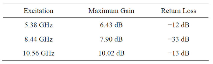
Table 1. Summary of sensing results.
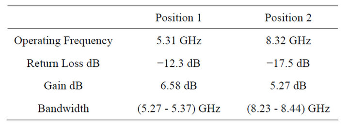
Table 2. Summary of sensing results.
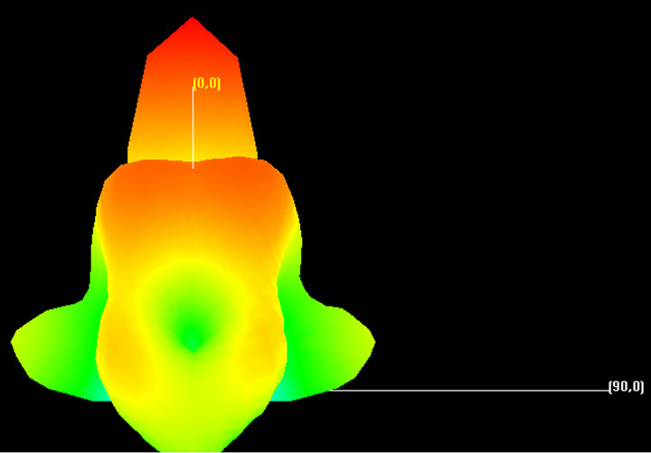
Figure 4. 3D radiation pattern for 8.44 GHz. For this band the maximum gain is 7.90 dB and the return loss is −33 dB.
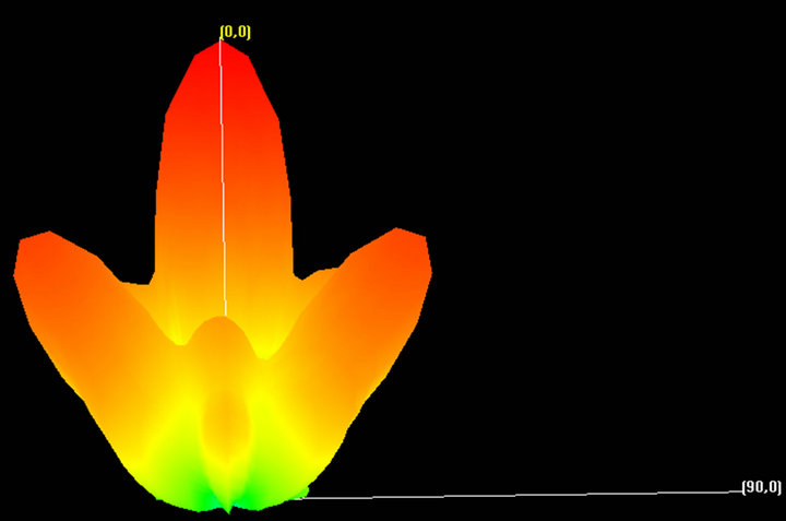
Figure 5. 3D radiation pattern for 10.56 GHz. For this band the maximum gain is 10.02 dB and the return loss is −13 dB.
to be one antenna. This has the advantage of reducing space requirements and making the two antennas required for cognitive radio communication lie in the same plane [8]. The combined structure is provided in Figure 12 with the same dimensions that mentioned in the previous two sections. Also the return loss of each band

Figure 6. The process of rotation for position 1 & 2 by 180˚.
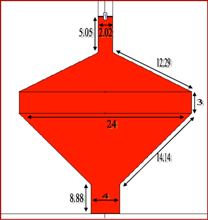
Figure 7. The reconfigurable antenna (all dimensions in mm).
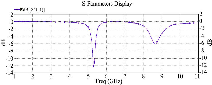
Figure 8. Return loss for position (1) (5.31 GHz).
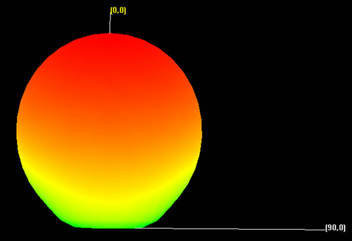
Figure 9. 3D radiation pattern for position (1) (5.31 GHz) with max gain 6.58 dB. Return loss for position (2) (8.32 GHz).
and 3D radiation pattern are shown in Figures 13-16 sequentially. As you can see the reconfigurable antenna
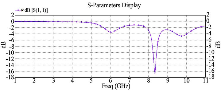
Figure 10. The return loss for position (2) at 8.32 GHz.
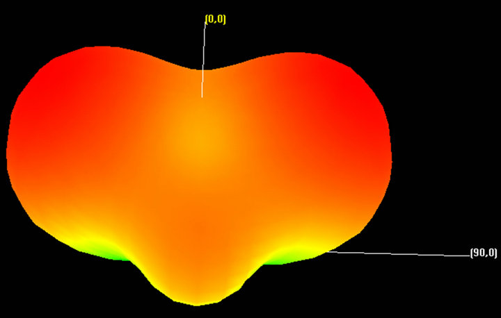
Figure 11. 3D radiation pattern for position (2) (8.32 GHz) with max gain 5.27 dB.
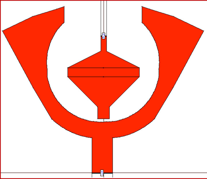
Figure 12. Combined structure (cognitive antenna structure).
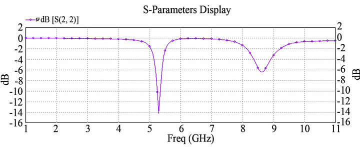
Figure 13. Return loss for cognitive with position (1) (5.28 GHz).
selects one band from the three bands results of sensing (UWB) via rotating by 180˚.
The summary of cognitive results is shown in Table 3.
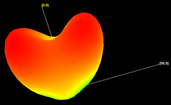
Figure 14. 3D radiation pattern for cognitive with position (1) (5.28 GHz) with max gain 5.10 dB.
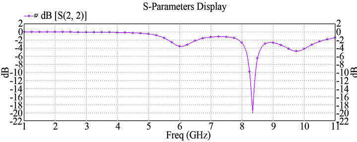
Figure 15. Return loss for cognitive with position (2) (8.34 GHz).
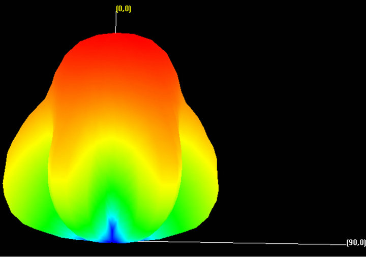
Figure 16. 3D radiation pattern for cognitive with position (2) (8.34 GHz) with max gain 6.89 dB.
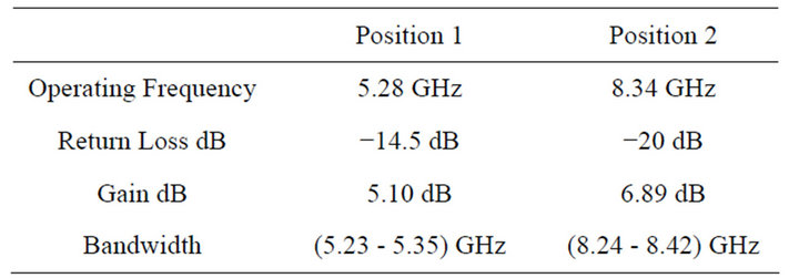
Table 3. Summary of cognitive results.
5. Conclusions
As we have seen in the last section we have sensing antenna, reconfigurable antenna and combination of them (cognitive radio). This design is not a new, it designed and fabricated in another paper but the new modification occurs in reconfigurable structure. We used the feature of narrow band excitation for rectangular shape to be satisfied by filling the separation region between two triangles that the reconfigurable consist of them. This shape allows the cognitive radio to work exactly at the bands of sensing results but in return, if triangles separated by a space, the cognitive radio will work at wide band. For example, it works from 2 - 5 GHZ with corresponding to position1 and 6 - 10 GHz with corresponding to position 2. In simple word, reconfigurable antenna we designed, selects exactly one of sensing frequencies results. Our design is more accurate than any design that has the same idea.
Surely, when we fill the region between triangles the, the impedance have to be 50 Ohm to match feeder, so the dimension also have to be changed in order to satisfy maximum power transfer.
As future work we will try to reduce the antenna sizes. Also the preferred substrate needs to be wisely selected. The permittivity of the substrate affects the size and performance of the antenna.
REFERENCES
- J. Mitola III, “Software Radios: Survey, Critical Evaluation and Future Directions,” IEEE Aerospace and Electronic Systems Magazine, Vol. 8, No. 4, 1993 pp. 25-36.
- Y. Tawk and C. G. Christodoulou, “A New Reconfigurable Antenna Design for Cognitive Radio Member,” IEEE Antennas and Wireless Propagation Letters, Vol. 8, 2009, pp. 1378-1381.
- FCC Spectrum Policy Task Force, “Report of the Spectrum Efficiency Working Group,” Technical Report, Federal Communications Commission, Washington DC, 2002.
- J. Mitola, “Cognitive Radio: An Integrated Agent Architecture for Software Defined Radio,” Ph.D. Dissertation, Royal Institute of Technology (KTH), Stockholm, 2000.
- M. Manteghi, “A Switch-Band Antenna for Software Defined Radio Applications,” IEEE Antennas and Wireless Propagation Letters, Vol. 8, 2009, pp. 3-5. doi:10.1109/LAWP.2008.2005256
- K. R. Boyle, et al., “Reconfigurable Antennas for SDR and Cognitive Radio,” Proceedings of the 2nd European Conference on Antennas and Propagation, Edinburgh, 11-16 November 2007, pp. 1-6.
- E. Ebrahimi and P. S. Hall, “A Dual Port Wide-Narrowband Antenna for Cognitive Radio,” Proceedings of 3rd European Conference on Antennas and Propagation, Berlin, 23-27 March 2009, pp. 809-812.
- P. Gardner, M. R. Hamid, P. S. Hall, J. Kelly, F. Ghanem and E. Ebrahimi, “Reconfigurable Antennas for Cognitive Radio: Requirements and Potential Design Approaches,” IET Seminar on Wideband, Multiband Antennas and Arrays for Defence or Civil Applications, London, 13 March 2008, pp. 89-94. doi:10.1049/ic:20080090
- Y. Tawk and C. G. Christodoulou, “A Cellular Automata Reconfigurable Microstrip Antenna Design,” Proceedings of IEEE Antennas and Propagation Society International Symposium, Charleston, 1-5 June 2009, pp. 1-4.