Journal of Electromagnetic Analysis and Applications
Vol.5 No.5(2013), Article ID:31433,4 pages DOI:10.4236/jemaa.2013.55032
Overlapped Subarray Architecture of an Wideband Phased Array Antenna with Interference Suppression Capability
![]()
1Department of Electronics and Communication Engineering, University Institute of Technology, University of Burdwan, Burdwan, India; 2Tata Consultancy Services, Kolkata, India; 3Department of Electronics and Telecommunication Engineering, Jadavpur University, Kolkata, India.
Email: quazi_alfred@yahoo.co.in
Copyright © 2013 Quazi Md. Alfred et al. This is an open access article distributed under the Creative Commons Attribution License, which permits unrestricted use, distribution, and reproduction in any medium, provided the original work is properly cited.
Received February 2nd, 2013; revised March 5th, 2013; accepted March 18th, 2013
Keywords: Phased Array; Subarray, Time-Delay; Overlapped Array
ABSTRACT
This paper presents a novel architecture of combining the linear array of antenna elements, where each antenna element has digitally selectable true time-delays as weights. Use of time-delays for beam-formation inherently makes the phased array network a wideband system. In particular, this technique envisage a new method of sharing antenna elements, by fixed overlapped sub-array architecture, which is able to maintain permissible element spacing to avoid grating lobe in antenna pattern. Moreover, this scheme additionally offers an easier null steering capability to the subarray architecture. This method essentially eliminates the need for intensive computation of complex weight vectors attached to each antenna element.
1. Introduction
An electronically steered phased array antenna system may be setup with phase shifters connected to each radiating element which in combine, transmits (receives) in directive way. By selecting appropriate phase gradient between successive radiating elements, it is possible to steer the beam away from the boresight (that is normal to the plane of the radiating elements). In most applications [1-6], a complex weight is used for each element, where the relative amplitude and phase gradient between successive elements determine the beam tilt from boresight and the sidelobe level. But phased array systems display a problem of undesired beam squint for wideband applications. The quality of beam shape and angular accuracy worsen with the increase of signal bandwidth, size of aperture and steering angle. This is due to the fact that phase shifters introduce nearly identical phase shift for other frequency of operation also, whereas the requirement is that of having a relative phase shift value proportional to the change in frequency. This problem is overcome by use true time delays instead of phase shifters [7-10]. Moreover, in the rapidly evolving wireless communication systems there is a growing need for implementing a phased array system which is capable of adjusting beam tilt angle, pattern shape and interference suppression preferably over multiple contiguous frequency band of operations at low cost overheads. Till date a wideband, fully steerable array using digitally controlled programmable time-delay units with the additional facility of precise null-suppression is prohibitively costly.
To overcome this problem, the subarray based feeding mechanism using both phase shifters and time-delays were proposed by Mailloux [11]. The subarray feeding may be conventional or overlapping. The method shown in Ref. [12], defines an elaborate architecture of using phase shifters in the main array combined by Butler matrix and time delays in the subarrays combined by corporate feed, can be used for above mentioned benefits. The architecture utilizes the concept of complex weight optimization for adaptive interference suppression. It is possible to place one (multiple) null(s) in the presence of strong interference by adaptive sidelobe cancellers or by optimizing the complex weight coefficients. Though these methods are popular for null formation but require extra hardware, computational resources and therefore cost. One solution in this regard is to control the signal characteristics at the subarray level. Often a large subarray is divided into few subarrays where time delays are used at subarray level and phase shifters are used at antenna levels. R. L. Haupt has elaborated a subarray null formation technique by optimizing complex weights in the subarray level [13] One major challenge in subarray scheme is controlling the grating lobe which is undesirable in beam shaping as well as null placements. This has been solved by using partially overlapped subarray technique where the overlap extent is optimized [14].
There are challenges for setting up an electronically steerable phased array system which is simultaneously wideband, programmable, very simple architecture requiring minimum additional hardware like power combiners and splitters, minimum computational efforts for suppressing deterministic interference (where the angle of arrival of jamming signal is known). There is also a need for array antenna technologies for the evolving multiband and multistandard radio commonly called Software Defined Radio.
The principal objective of the present communication is to provide improved overlapped subarray architecture for the following requirements:
To develop wideband phased array system with programmable beam forming capability;
To null at the angle of interference.
2. Time-Delayed Matrix at Antenna Level
Unlike conventional use of phase-shifters in beam-formation, focus is given here on time-delay units (delay-lines). The time-delay unit inserts progressive phase gradient between antenna elements, hence by designing a Programmable Switching Matrix (PSM) beam steering and beam synthesis [9,10,12] is possible which is explained as follows. This offers the advantage in designing a wideband phased array system.
Let in Figure 1, a six (6) element linear array is arbitrarily chosen where the antenna elements are separated by distance “d” and is connected with two levels of delay elements. In each level, every antenna is connected through three parallel path having delay elements, multiples of unit delay T (here ) are selected by SP3T (Single Pole Three Throw) PIN switches. Here, A and B are the PIN switches where A0, A1, A2 and B0, B1, B2 are the six (6) control inputs and corresponding logical bits. Inputs to the switches may be controlled (ON/OFF) by 8 bit-microcontroller where only 6 bits are required for this situation. In each level, at least and at most only one path of delay element is selected and the delay elements of the two levels are added to provide total delay and hence delay gradient. This condition therefore demands some bit pattern to be redundant.
For example, microcontroller sets the switching pattern as A0 = 0, A1 = 1, A2 = 0 and B0 = 0, B1 = 0, B2 = 1, then inter-element differential delay or delay gradient becomes +2 T. Among 64 possible combinations only seven (7) are useful as the other combinations are either redundant or they do not conform the condition mentioned previously.
Let, A0 = 0, A1 = 0, A2 = 1 and B0 = 0, B1 = 1, B2 = 0 or phase gradient  and inter-element distance
 , then the beam is steered to the angle approximately 100 deg (99.6 deg) or 10 deg Eastward direction from broadside (90 deg). Only the seven (7) non-redundant combinations and corresponding beam positions are given in Table 1. Hence the main beam (SUM pattern) can be steered to seven (7) discrete positions in the space by loading proper digital bits from the microcontroller output. Resolution can be enhanced by adding more levels vertically to the feeding lines across each antenna elements.
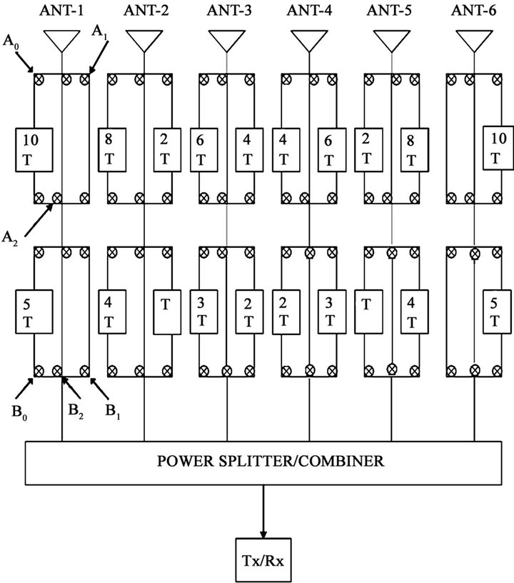
Figure 1. PSM for 6-element linear array.
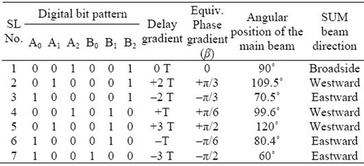
Table 1. Switching pattern for 6 element linear array and corresponding beam direction.
3. Overlapped Subarray Architecture for Interference Rejection
Another requirement of this communication is to provide steerable nulls to the direction of arrival (DOA) of interferences.
Here a linear array of N numbers of radiating elements is divided into two (M = 2) subarrays, each consisting of (N − 1) elements as shown in Figure 2. The two horizontal subarrays are overlapping to an extent of (N − M) elements. Thus, the element locations that are grouped in only one of the two subarrays, are the 1st element and the Nth element. Hence, this structure maintains the spacing in both element level as well as subarray level as the same.
Each antenna element, at the main array level, is connected to a programmable time delay matrix which offers limited scanning at the discrete angular positions. The outputs of the time-delay matrix for individual elements are combined to form two subarrays as explained before. At the subarray level, the outputs of the two subarrays are combined in a manner where a multi-bit digital phase shifter is connected to any only one of the subarrays.
The introduction of multi-bit phase-shifters at the subarray level offers null forming option at various positions. For the null formation, phase shifter at subarray is finely tuned to form difference pattern at the predetermined angle of strong interference arrival. Thus, when the angle of arrival of jamming signal is known, a simple expression is evaluated to compute the phase shifter value required to be imposed in the subarray level. This phenomenon is illustrated through the mathematical formulation by Equation (1) to Equation (3).
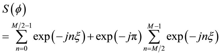
The sum pattern  of the N linear elements in each subarray is given by the following expression.
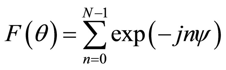 (1)
(1)
where, 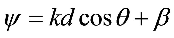 , phase constant
 , dx is inter-element spacing, θs is the elevation angle form the end-fire direction, β is the phase difference required to maintain between antenna elements.
The main beam (sum pattern) will be formed to the desired direction (target) θ0 at ψ = 0 or essentially phase gradient will be maintained as .
.
Again, the difference pattern of M No. of subarray is expressed by following equation.
 (2)
(2)
where  and difference pattern with broad null will be in α0 direction (interference) when
 . Hence the resultant pattern
  is given by following.
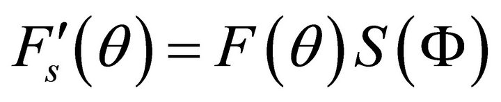 (3)
(3)
Figure 3 depicts the sum pattern of 7-element linear array of isotropic radiators with the main beam at boresight direction (θ = 90˚). Assuming that the jamming or interference signal is known to be getting injected from an angle of θ = 60˚, we place a null there, by setting the digital phase shifter with a value that is a function of cosine of 60˚. This is shown in Figure 4.
Main beam can be steered to other angles also and similarly null can be imposed to the interference angle.
The use of time-delay matrix at the array level ensures wideband scanning system while the use of multibit digital phase shifter at the subarray level ensures a precise null placement for a given frequency of jamming signal.
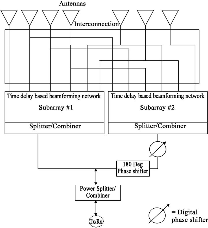
Figure 2. Overlapped subarray architecture for linear array.
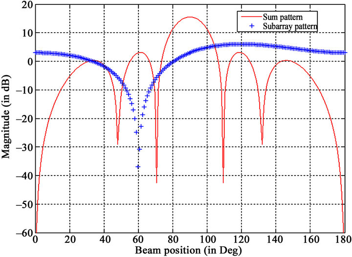
Figure 3. Sum pattern at broadside (90˚) direction.
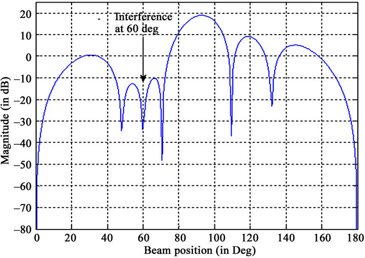
Figure 4. Interference suppression at 60˚.
4. Conclusion
This new architecture may find its importance in phased array radar for simultaneous beam-forming and interference cancellation while tracking the target. In wireless domain, it also removes the restriction of using multiple types of feed network design for the cases where the same wireless service is allotted different spectrums in different regions of operation within a broad frequency band allocation.
REFERENCES
- A. Chakroborty, B. N. Das and G. Sanyal, “Beam Shaping Using Nonlinear Phase Distribution in a Uniformly Spaced Array,” IEEE Transactions on Antennas and Propagation, Vol. 30, No. 5, 1982, pp. 1031-1034.
- J. F. DeFord and O. P. Gandhi, “Phase Only Synthesis of Minimum Peak Sidelobe Patterns for Linear and Planar Arrays,” IEEE Transactions on Antennas and Propagation, Vol. 36, No.2, 1988, pp. 191-201.
- E. C. Dufort, “Low Sidelobe Electronically Scanned Antenna Using Identical Transmit Received Module,” IEEE Transactions on Antennas and Propagation, Vol. 36, No. 3, 1988, pp. 349-356.
- H. Steyskal, “Synthesis of Antenna Pattern with Prescribed Nulls,” IEEE Transactions on Antennas and Propagation, Vol. 32, No. 2, 1982, pp. 273-279. doi:10.1109/TAP.1982.1142765
- H. Steyskal, “Simple Method for Pattern Nulling by Phase Perturbation,” IEEE Transactions on Antennas and Propagation, Vol. 31, No. 1, 1983, pp. 163-166.
- R. S. Elliot and G. J. Stern, “A New Technique for Shaped Beam Synthesis of Equispaced Array,” IEEE Transactions on Antennas and Propagation, Vol. 32, No. 10, 1984, pp. 1129-1133. doi:10.1109/TAP.1984.1143216
- S. K. Sanyal, A. Goswami, D. R. Poddar and S. K. Chowdhury, “A Microprocessor Controlled Programmable Switching Module for Phased Array Applications,” Proceedings of IEEE, Vol. 76, No. 5, 1988, pp. 636-638. doi:10.1109/5.4451
- K. Ewan and F. Barrett, “Antenna Having Elements with Programmable Digitally Generated Time-Delays,” US Patent No. 5130717, 1992
- S. K. Sanyal, Q. M. Alfred and T. Chakravarty, “A Novel Beam Switching Algorithm for Programmable Phased Array Antenna,” Progress in Electromagnetic Research Vol. 60, 2006, pp. 187-196. doi:10.2528/PIER05122502
- Q. M. Alfred, T. Chakravarty and S. K. Sanyal, “A Novel Wideband Subarray Technique for Shaped Pattern Generation and Adaptively Interference Interference Rejection,” International Journal of Infrared and Millimeter Waves, Vol. 29, No. 3, 2008, pp. 249-260. doi:10.1007/s10762-007-9320-y
- R. J. Mailloux, “Subarray Pattern Control and Null Steering for Subarray Antenna System,” US Patent No. 4246525, 1981.
- Q. M. Alfred, T. Chakravarty and S. K. Sanyal, “A Novel Schematic for Calibration of Large Phased Array Antenna Using Programmable Time-Delay Units,” Progress in Electromagnetics Research, Vol. 65, 2006, pp. 81-89. doi:10.2528/PIER06080301
- R. L. Haupt, “Phase Only Adaptive Nulling with Genetic Algorithm,” IEEE Transactions on Antennas Propagation, Vol. 45, No. 6, 1997, pp. 1009-1015.
- G. F. Lewis, “Ovelapping Subarray Architecture,” US Patent No. 7265713, 2007.