Journal of Electromagnetic Analysis and Applications
Vol.4 No.4(2012), Article ID:18615,5 pages DOI:10.4236/jemaa.2012.44021
Design of Bidirectional Coupling Circuit for Broadband Power-Line Communications
![]()
1Department of Electronics and Communication Engineering, Durgapur Institute of Advanced Technology & Management, Durgapur, India; 2Department of Electronics & Electrical Communication Engineering, Indian Institute of Technology Kharagpur, Kharagpur, India; 3Department of Electronics and Telecommunication Engineering, Jadavpur University, Kolkata, India.
Email: samserali@rediffmail.com
Received February 14th, 2012; revised March 12th, 2012; accepted March 24th, 2012
Keywords: Coupling Circuits; Line Trap Circuit; Broadband
ABSTRACT
This paper deals with the design of bidirectional coupler for broadband power line communication and the impedance matching technique with the power line. This coupler can be used for both transmitting and receiving the data, acting as transceiver. The impedance mismatching problem is also solved here using line trap circuit. The coupler circuit is capable of transmitting or receiving modulated signals with carrier frequency of 15 MHz which can be used for domestic as well as distribution power networks. Laboratory prototype tested using power line network consists of electrical household appliances and results show that the circuit is able to facilitate bidirectional band pass transmission.
1. Introduction
Power lines may be a cheap and good networking option in the sense that they are almost a universally present infrastructure. The conventional power line can be effectively utilized for broadband communication. The low voltage (LV) electrical power distribution network, which is a widely spread network with distribution transformers with many loads connected in parallel, presents the most efficient medium for data and voice communications such as fast Internet access and telephone service. The high voltage (11 KV) electricity distribution network can be applicable for this purpose, which can be an alternative of highly expensive optical fiber network.
Coupling circuits for power line communication (PLC) are available with pass band of maximum 150 KHz which includes CENELEC B, CENELEC C and CENELEC D bands [1,2]. If power line communication system is designed for higher frequencies it will be the cheapest medium for high speed internet access. Currently internet access using power line network is in the focus of various research activities [3]. The transmission of high speed data through power distribution network will be possible if such a coupling circuit is successfully designed.
Section 2 presents architecture of typical PLC System while Section 3 & 4 present and explain designs of Coupler and Line Trap circuit. Section 5 represents experimental results which show the coupler circuit presented here can facilitate bidirectional communication.
2. PLC System
A typical PLC system is made up of traditional power line, bidirectional coupling circuits and line trap circuits. The coupling circuits which act as transceivers (transmitters and receivers) are needed for generation and recovery of the high frequency message signal. The method used for coupling the signal to the power line and decoupling from the power line is based on Differential Mode Coupling that involves the live wire as one terminal and the neutral wire as another terminal [4]. The coupling circuits are used to couple the modulated carrier signal onto and from the power line without compromising the power frequency 50 Hz insulation level. The PLC modem along with the bidirectional coupling circuits at the sending end (i.e. after trap circuit) will convert the information into digital data packets which are digitally modulated with a higher carrier frequency (5 MHz - 15 MHz). The modulated signal is then coupled on the 50Hz power system network and hence being transmitted. At the receiving end, the information will be retained by a demodulation process. The impedance of a power line is very low. Sometimes it reduces to a few ohms. So, there is a chance of mismatch between the coupler impedance and power line impedance. For that a line trap circuit is required to trap the low impedance power signal and offer high impedance to the coupled high frequency signal. The architectures of typical PLC systems with trap circuits are shown in Figures 1 and 2.
3. Design of Coupler
The coupler is the heart of the PLC system. The low voltage coupler shown in Figure 3 is suitable for userend distribution network (220 V - 440 V). High voltage coupler shown in Figure 4 can be used for coupling data before step down transformers (11 KV - 220 V) i.e. on the 11 KV distribution network. The same coupler circuit is used for both transmitting and receiving data. For transmitting data live-neutral is connected to power line and data input side is connected to low voltage data source. Similar connection is followed for receiving data. For transmitting data through coupler circuit, data flows from data input side to live-neutral and data flows in reverse direction for receiving data.
Transformer coupling circuits are extensively used in power line communication system because transformers provide galvanic isolation from power line and act as limiter when saturated by high voltage transient. The transformer with turn’s ratio 20:1 is made of ferrite core because ferrite core introduces fewer losses at higher frequency than other cores. The combination of series capacitors and parallel inductors forms a high pass filter
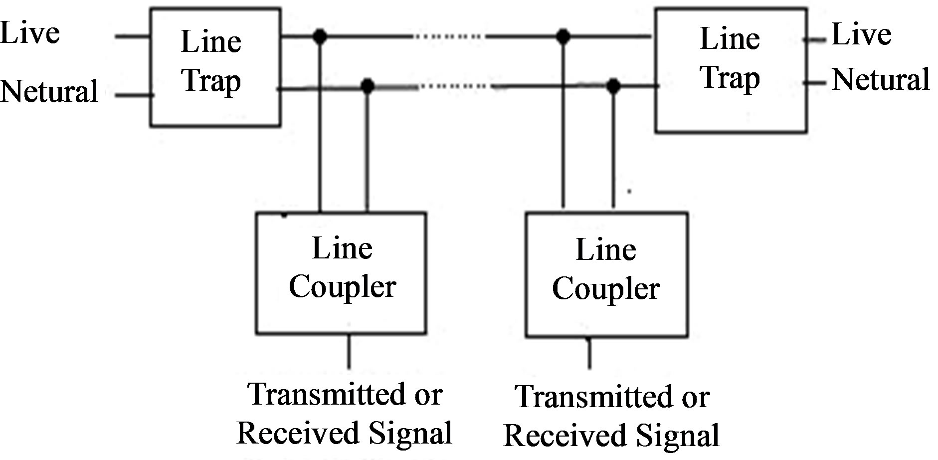
Figure 1. Architecture of typical low voltage PLC system.
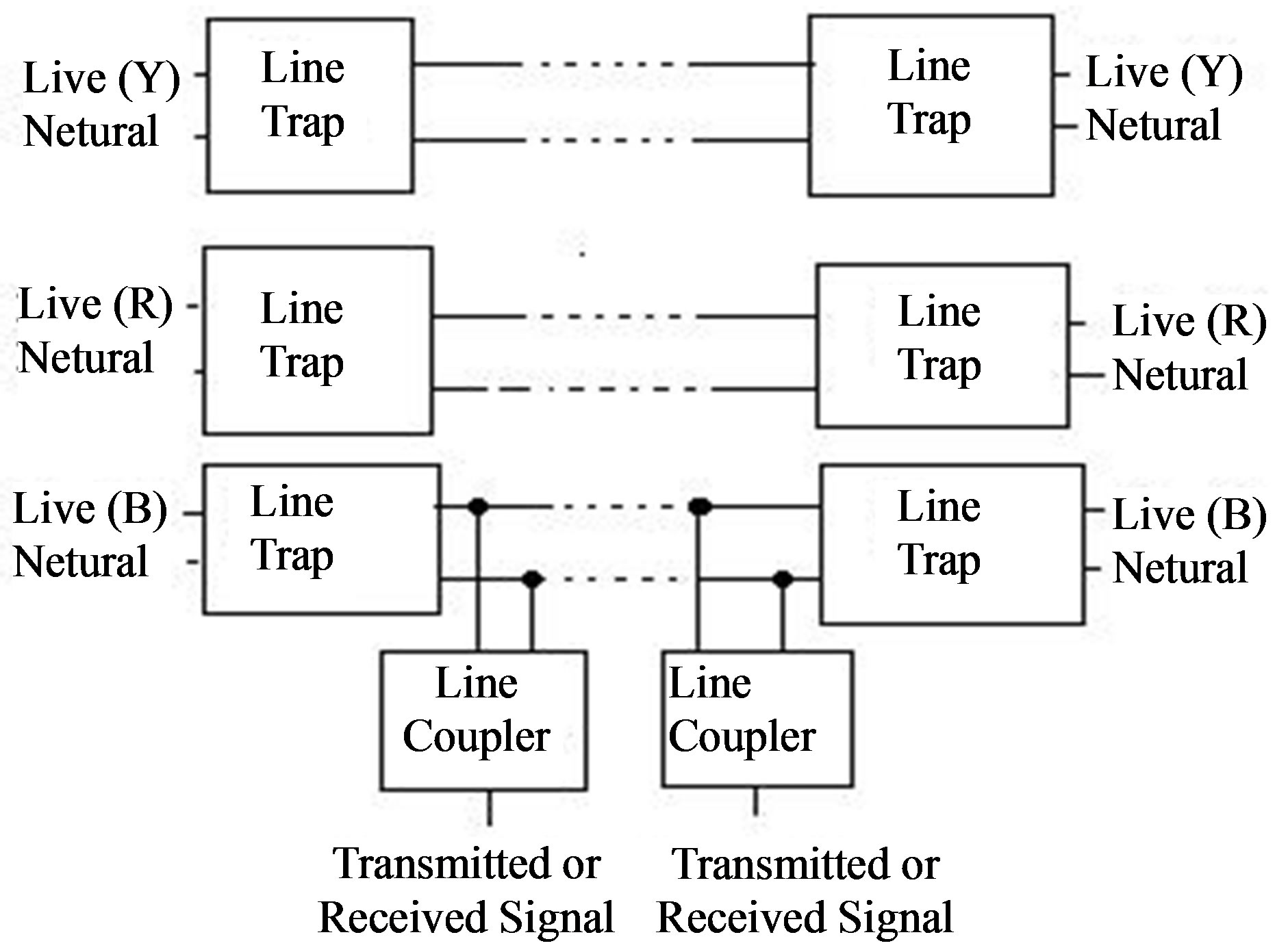
Figure 2. Architecture of typical high voltage three phase PLC system.
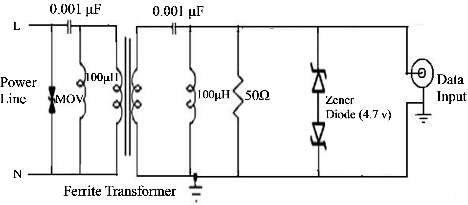
Figure 3. Low voltage bidirectional coupler circuit.

Figure 4. High voltage bidirectional coupler circuit.
with cutoff frequency 1 MHz. This filter blocks 50 Hz and other noise signals present in power line but allow passing the message signals of higher frequency (5 MHz - 10 MHz). In addition, parallel resonant circuits can be used here to improve overall bypass effect. Back to back zener diodes are used here to clamp the voltage transients at the secondary side of the transformer and limiting any high voltage that may creep into the data circuit. A resistor is connected in parallel with the capacitor to discharge the capacitor in order to minimize the hazard of high voltage peaks caused by the stored charge in capacitor. The metal oxide varistor (MOV) protects the circuit from any incoming surge from the power line; basically the metal oxide varistor provides protection against very large transients on the power line.
The high voltage coupler which can work up to 11 KV for three phase lines is shown in Figure 4. The main properties of this high voltage coupler are that the coupler is connected between the two phases of the power line and the secondary side of the second transformer is grounded. Two ferrite transformers are used here to achieve desired isolation. The series combination of inductors and capacitors forms the high pass filter and the parallel combinations improve the bypass effect of the circuit. Though the high voltage coupler is connected between only two phases of the power line, line trap circuit is needed for all three power lines differently as shown in Figure 2.
4. Design of Line Trap Circuit
The line trap used here is actually multiple-T-filter configuration, which is made up of coils and capacitors. It is connected in series with the power line and presents high impedance to the carrier band of 1 MHz to 15 MHz. The T-filter configuration is chosen because of its advantage of working well in low impedance line. However, for a multiple filter such as double-T-filter, it will have a resonant rise lower in frequency than the trouble frequency [5]. A RC-shunt is used to overcome this problem. A double-T-filter consists of two T-filter stages connected in series and symmetrical way [6]. Typical design of such a trap circuit is shown in Figure 5.
The transmission (ABCD) parameters of the trap can be written as,
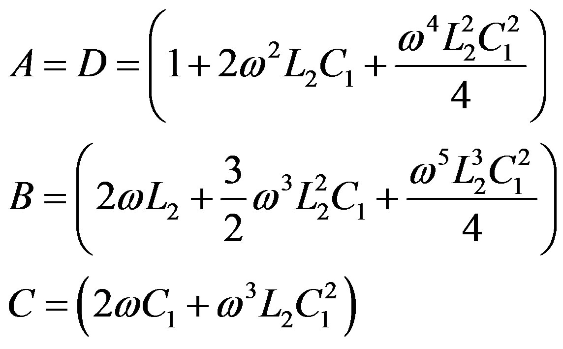
From this it can be verified that an isolation of at least 53 db between the power signal and the FSK signal is achievable at 13.2 Hz frequency. This is sufficient for the impedances seen in normal power distribution networks [7].
5. Results and Discussion
In the laboratory multipurpose power line was taken for experiment. Couplers along with Line trap circuits were connected to the plug sockets of Power-line. Binary data was sent as a binary FSK modulated waveform (10 V, 15 MHz frequency was used for representing a binary “1”, and 3 V, 5 MHz for representing a binary “0”) with the help of Agilent 33220A, an arbitrary function generator and coupled to the power-line through the coupler. The FSK modulated waveform, before the transmitting side coupler input is shown in Figure 6 and FFT of this waveform shown in Figure 7. The waveforms were observed on Tektronix TDS 1002, a Digital Storage Oscilloscope. After connecting the data input to the coupler circuit the amplitude of the waveform was attenuated to 9.17 V and after passing through high pass filter the signal was again attenuated to 7.42 V, as shown in Figure 8.
The final output signal of the transmitting side coupler was attenuated to 6.64 V after passing through the ferrite core transformer, as shown in Figure 9.
The same coupler circuit was used for receiver side and data was extracted by demodulation of the FSK
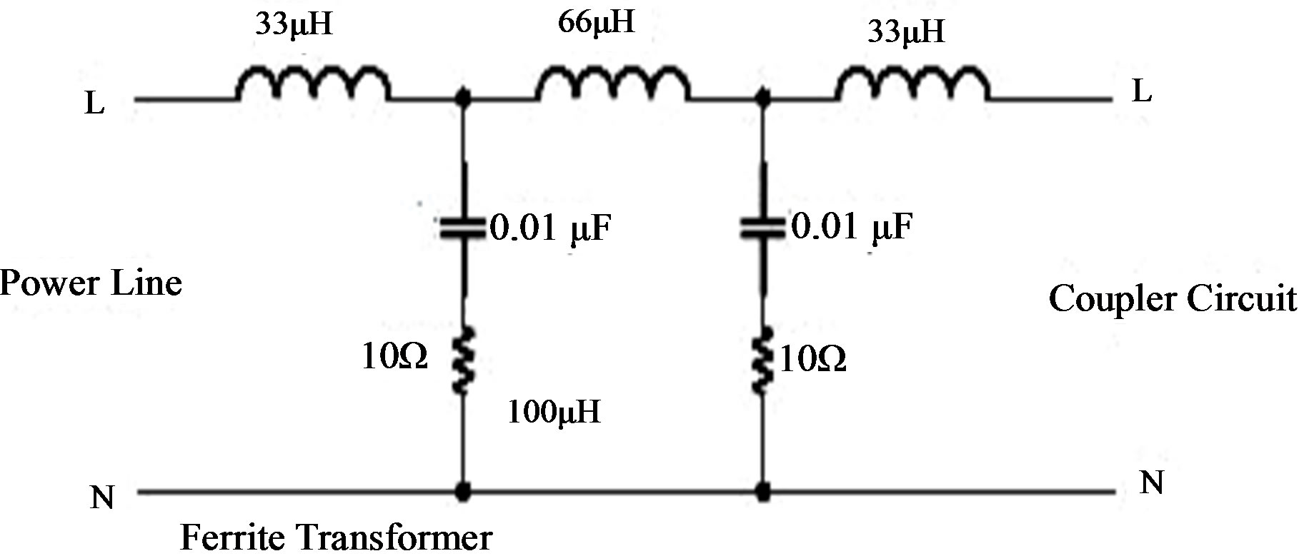
Figure 5. Line trap circuit.

Figure 6. FSK modulated waveform at the input of the transmitting side coupler.
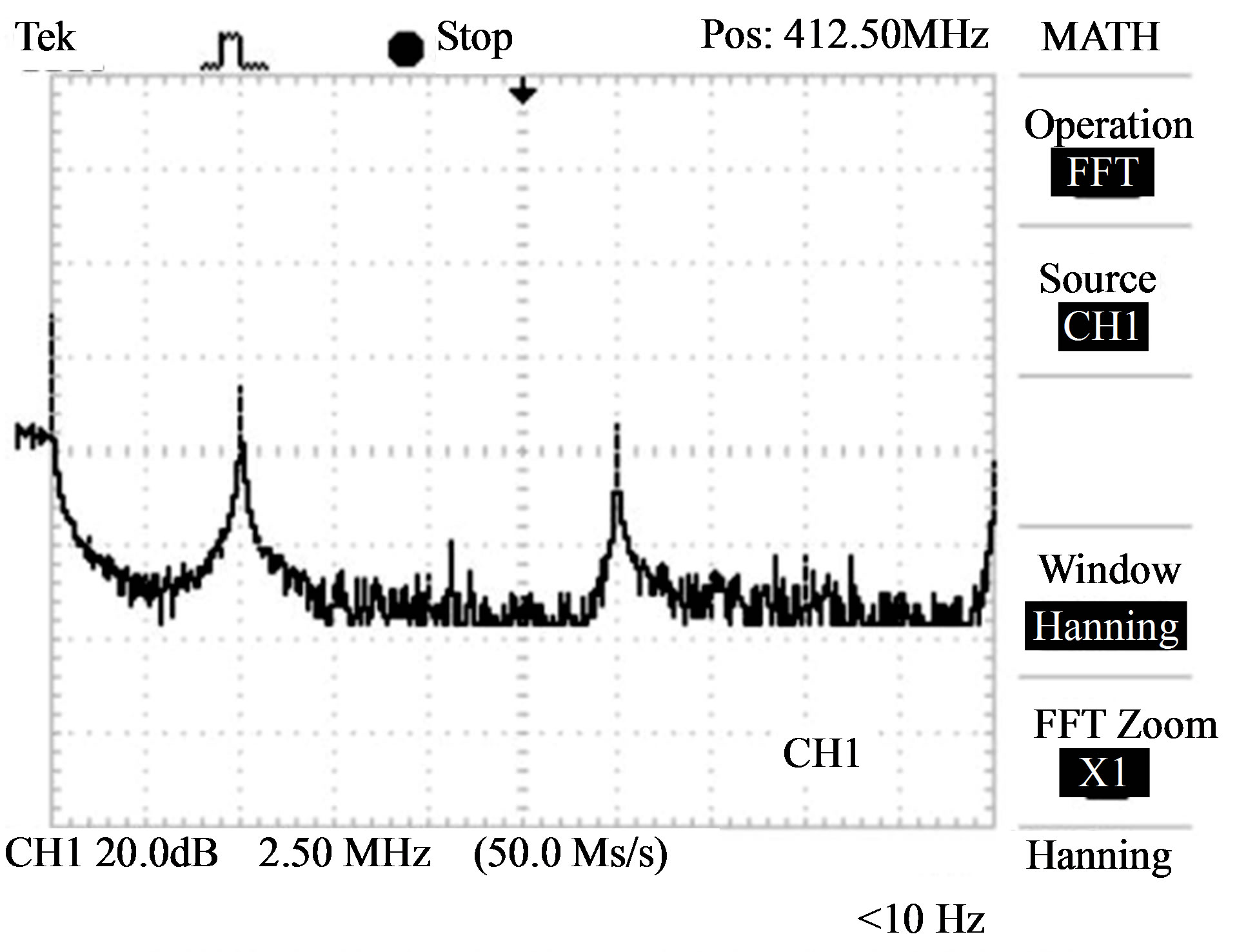
Figure 7. FFT of the FSK modulated waveform at the input of transmitting side coupler.
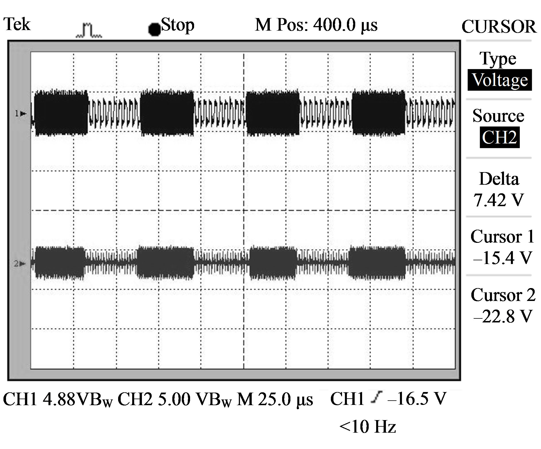
Figure 8. FSK modulated waveform after the filter circuit of transmitter side coupler.
modulated signal. Here data was captured at various distances from the transmitting side coupler. Figure 10 shows that the signal received at 10 meter distance from the transmitting side coupler, attenuated to 5.08 V but its bit patterns remain unaltered and Figure 11 shows the FFT of the same signal.
The received is signal also measured at a distance of 30 meter and 60 meter from the transmitter. Figure 12 shows that the coupler attenuates 10 V signal to 2.73 V measured at 60 meter distance and the SNR of the received signal is sufficient for the demodulator to extract the binary data. The FFT of the received signal is shown in Figure 13. The electrical household appliances introduce noise and variable impedance to the line in the distribution side of the power line network [7]. The transient response due to rapid load swings was captured and the received signal was attenuated to a 560 mV when one such load (2 KW heater) switched on as shown in Figure 14. FFT of the received signal heater loading is shown in Figure 15.
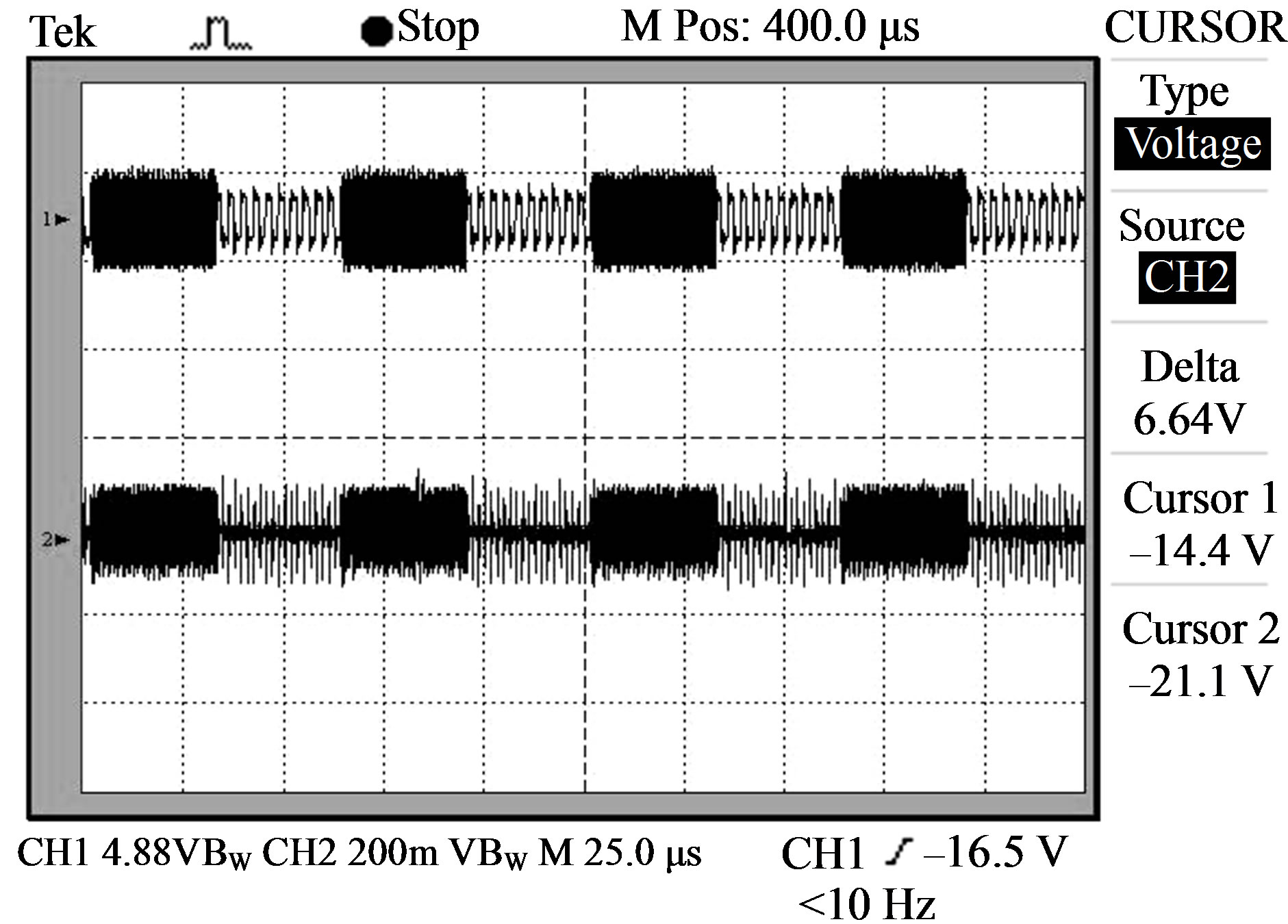
Figure 9. FSK modulated waveform at the output of transmitting side coupler.

Figure 10. FSK modulated waveform at the receiving side coupler output.
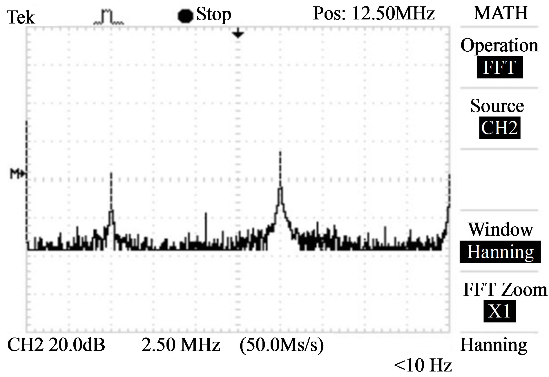
Figure 11. FFT of the received signal at a distance of 10 meter from the transmitting side coupler.
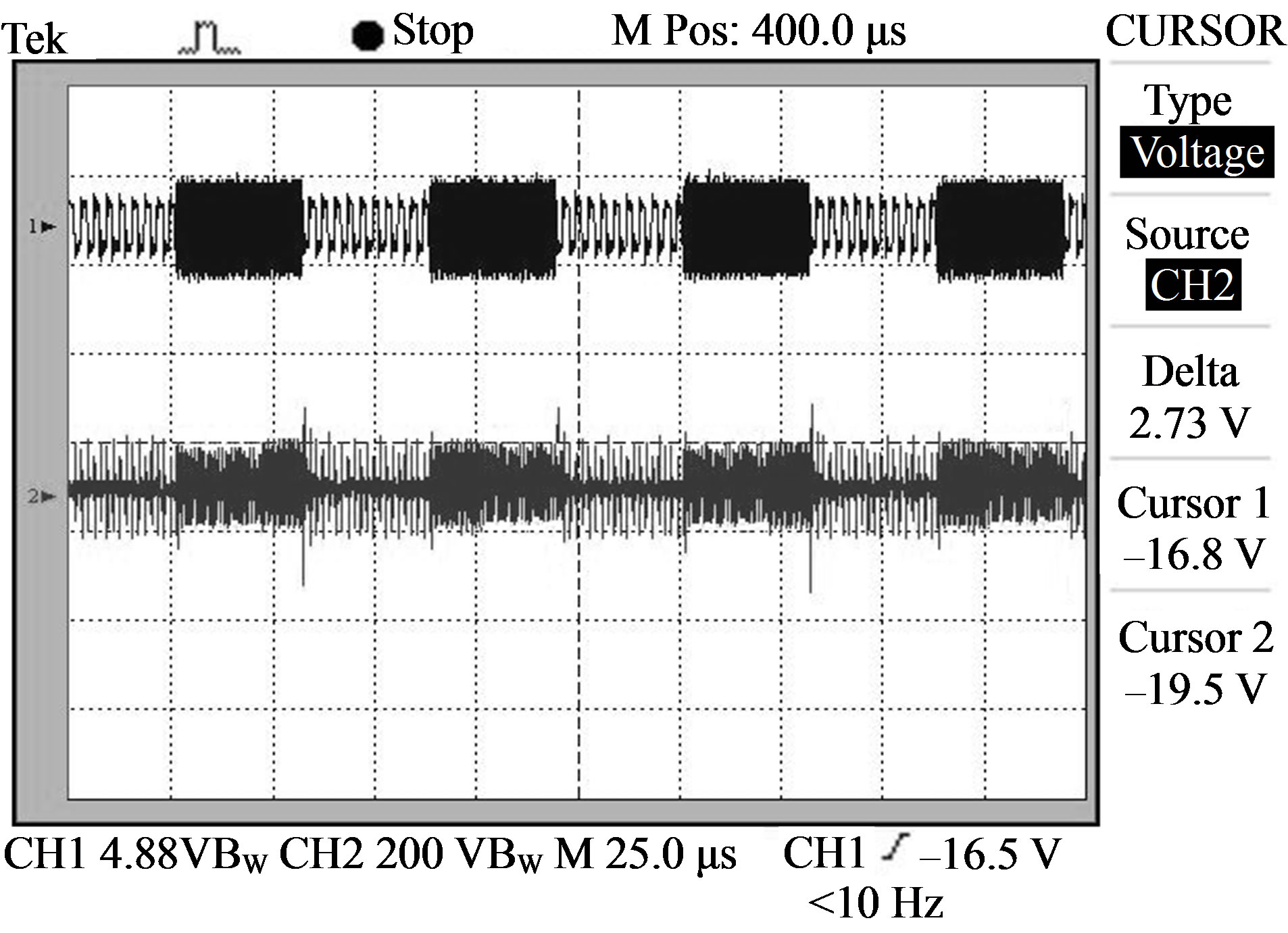
Figure 12. Received signal at a distance of 60 meter from the transmitting side coupler.
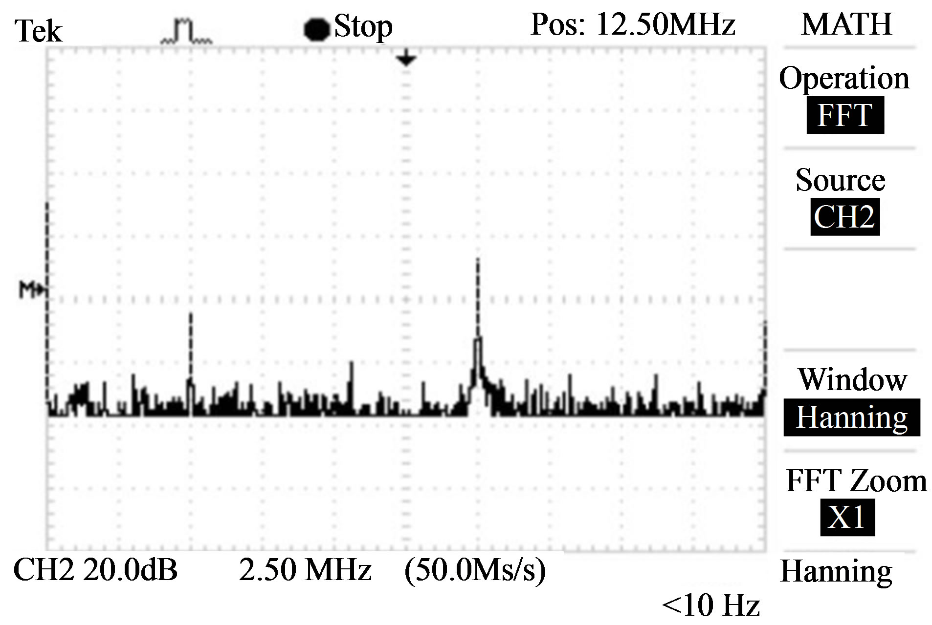
Figure 13. FFT of the received signal at a distance of 60 meter from the transmitting side coupler.
For each measurement, transmitted FSK signal is taken on CH1 of DSO, acts as a reference and from the above mentioned figures it is clear that the received signals are the attenuated versions of the transmitted signals. The transmitted and received bit streams are similar and
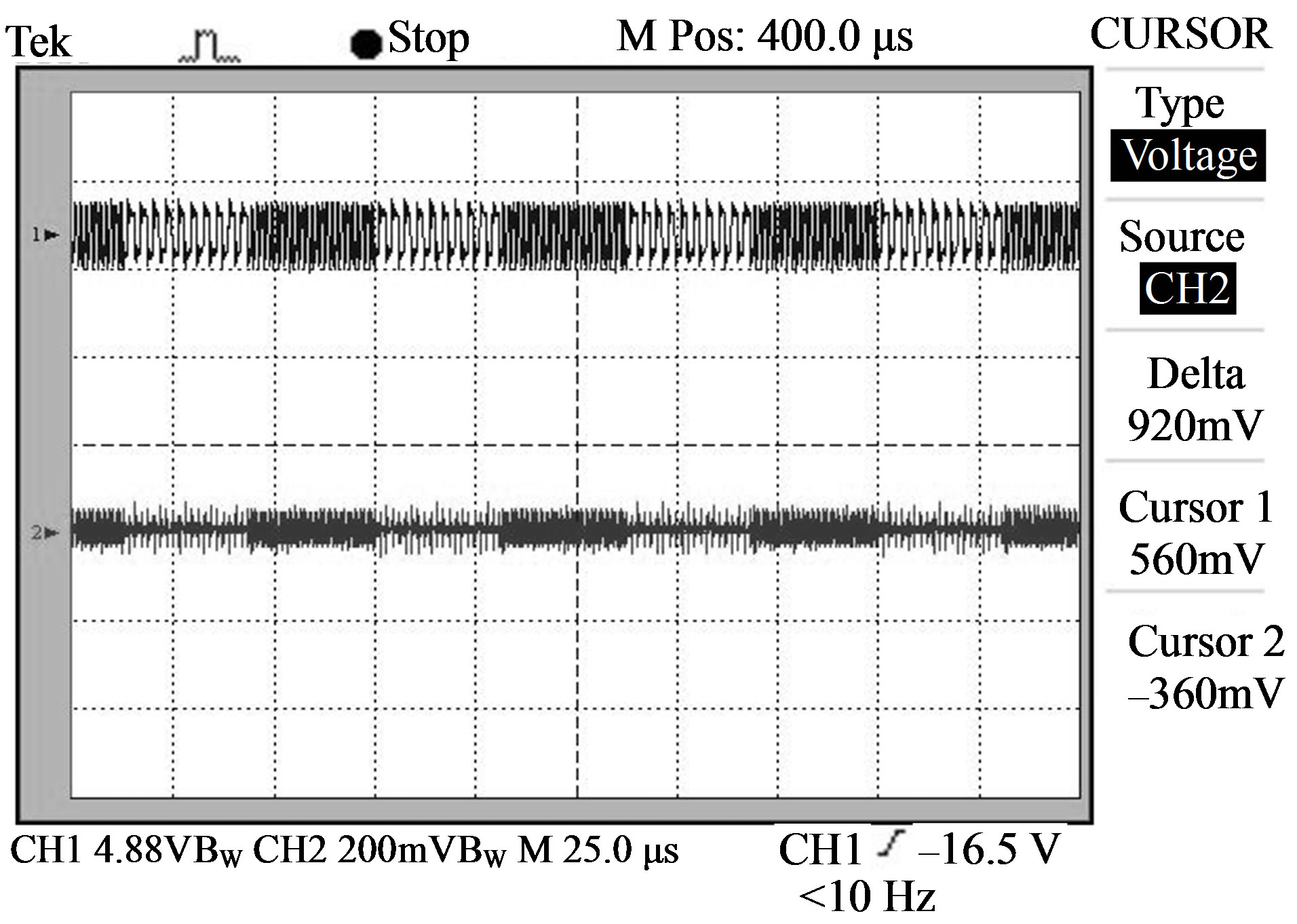
Figure 14. Received signal under heater loading.
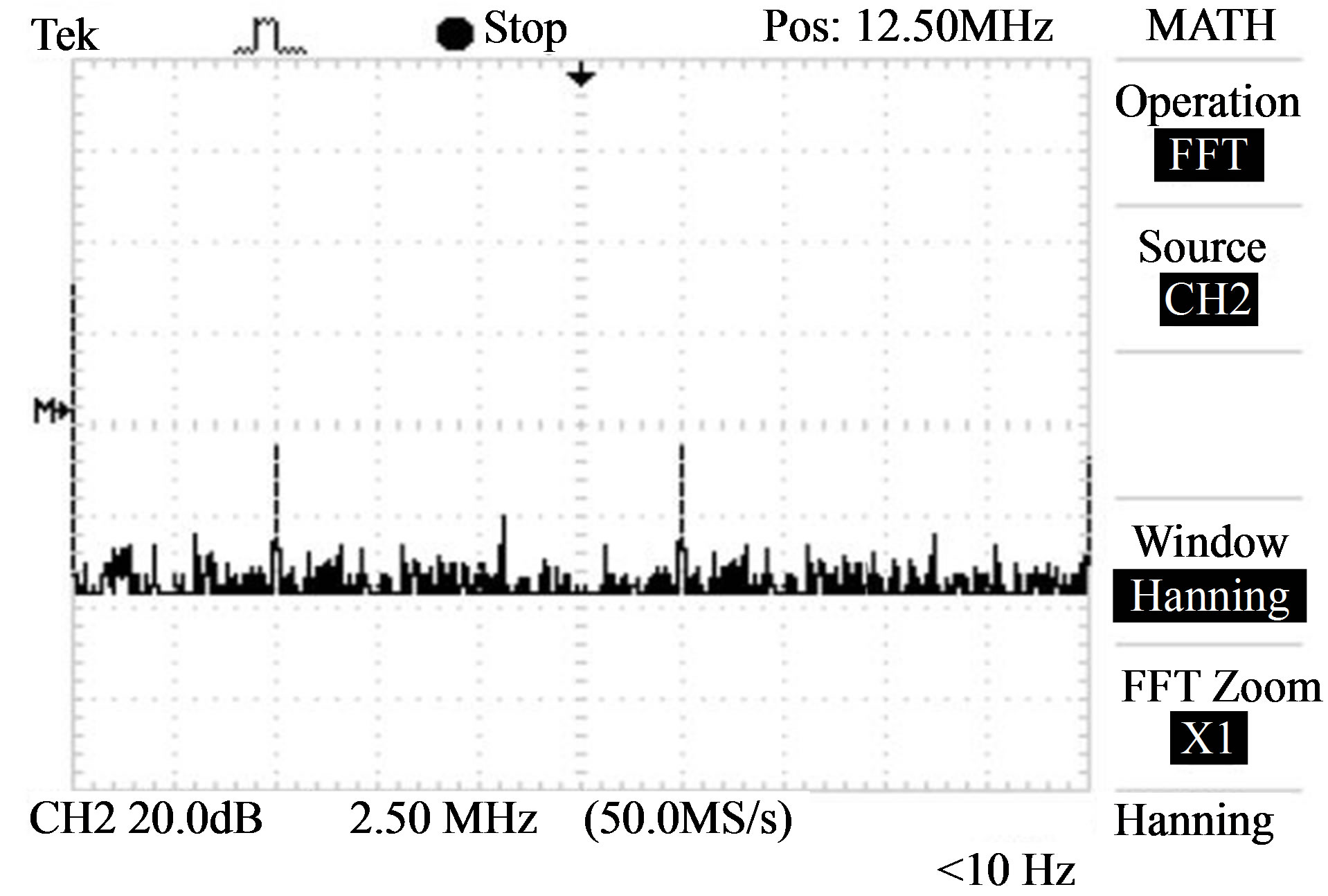
Figure 15. FFT of the received signal under heater loading.
two different frequency components are clearly discernable and match with the transmitted bit stream, in the FFT signals.
The voltage transfer ratio of the coupler along with power line was also measured and shown in Figure 16. The linear characteristic of the voltage transfer ratio suggests that the transmitted signal would not suffer distortion by communication channel.
6. Conclusion
The proposed coupler is well suited for transmitting high frequency communication signals to high voltage power lines and can be demodulated effectively by the digital communication receivers existing today. Impedance mismatching problem between the coupler impedance nd power line impedance is also solved using line trap circuit. This coupler can be effectively used for Broad band
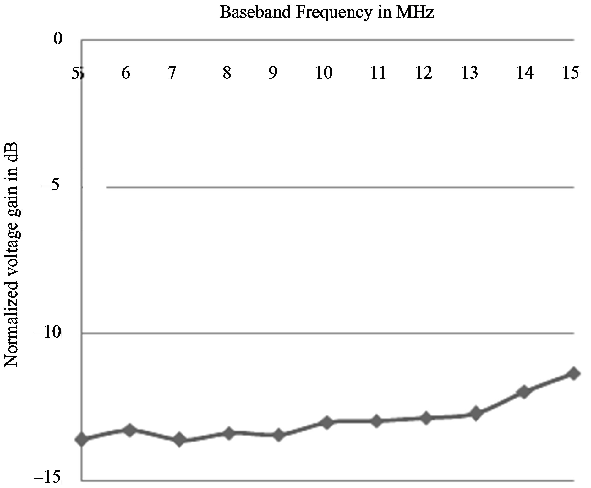
Figure 16. Voltage transfer ratio of the coupler along with power line.
Communication (5 MHz - 15 MHz) in domestic as a well as distribution power networks.
REFERENCES
- P. A. J. van Rensburg, “Design of a Bidirectional Impedance-Adapting Transformer Coupling Circuit for LowVoltage Power-Line Communications,” IEEE Transactions on Power Delivery, Vol. 20, No. 1, 2005, pp. 64-70. doi:10.1109/TPWRD.2004.835260
- DOMOLOGIC, “Konnex PL132—Power-Line-Communication Using the CENELEC-C-Band,” DOMOLOGIC Home Automation GmbH, 2003.
- P. Langfeld and K. Dostert, “OFDM System Synchronisation for Powerline Communications,” Proceedings of 4th International Symposium on Power-Line Communications and its Applications, Limerick, 5-7 April 2000, pp. 15-22.
- American National Standard, “IEEE Guide for PowerLine Carrier Applications,” ANSI/IEEE Std. 643-1980, 1981.
- R. L. Ozenbaugh, “EMI Filter Design,” 2nd Edition, Marcel Dekker Inc., New York, 2001.
- P. L. So and Y. H. Ma, “Development of a Test Bed for Powerline Communication,” IEEE Transactions on Consumer Electronics, Vol. 50, No. 4, 2004, pp. 1174-1182. doi:10.1109/TCE.2004.1362516
- M. Zimmermann and K. Dostert, “A Multipath Model for the Power Line Channel,” IEEE Transactions on Communication, Vol. 50, No. 4, 2002, pp. 553-559. doi:10.1109/26.996069