Journal of Electromagnetic Analysis and Applications
Vol. 3 No. 12 (2011) , Article ID: 16519 , 7 pages DOI:10.4236/jemaa.2011.312078
Compact Bluetooth/UWB Antenna with Multi-Band Notched Characteristics
![]()
1Faculty of Engineering, Helwan University, Helwan, Egypt; 2Faculty of Electronic Engineering, Menoufiya University, Menouf, Egypt.
E-mail: ahmed_mahmoud03@h-eng.helwan.edu.eg
Received October 1st, 2011; revised November 10th, 2011; accepted November 27th, 2011.
Keywords: Ultra-wide band (UWB), Bluetooth, Band notched, FEM, FIT
ABSTRACT
A small-sized, low-profile, and planar dual band antenna for Bluetooth (2.4 - 2.484 GHz) and ultra-wideband (UWB) (3.1 - 10.6 GHz) with multi-band notched antennas is presented. Two antennas A and B with different types of slots are used to obtain tri-band notched characteristic. In antenna A notched bands, 5 - 6 GHz for WLAN, and 3.3 - 4 GHz for WiMAX, are achieved using a U-slot in ground structure and in the radiating patch. In antenna B two notched bands at 3.3 - 4 GHz, for WiMAX and 7.2 GHz for C-band satellite communication systems are achieved by using a U-slot in ground structure and a H-shaped slot in the radiating patch. The radiation characteristics of the two antennas are calculated using a commercial EM simulator based on Finite Element Method (FEM) and the Finite Integration Technique (FIT). The two antennas show acceptable gain flatness with stable omnidirectional radiation patterns across the integrated Bluetooth and UWB bands.
1. Introduction
Among short-range wireless communication systems, Ultra-wideband (UWB) technology, with a frequency allocation of 3.1 - 10.6 GHz, has gained a lot of popularity from researchers and the wireless industry alike due to the high data transfer rate (110 - 200 Mb/s) and low power consumption. The design of UWB antennas is one of the major factors affecting the progress of UWB technology. As a result, UWB antenna design has been studied much in recent years [1-4]. UWB antennas must be electrically small and inexpensive without compromising on performance. Omnidirectional radiation pattern is desired in order to be well suited for ad hoc networks with arbitrary azimuthal orientations. However, over the designated frequency band, there exist some narrow bands for other communication systems, such as WiMAX operating in the 3.3 - 3.7 GHz band, WLAN operating in the 5.15 - 5.825 GHz band, and C-band satellite communication systems at 7.2 GHz. They may cause communication interference with the UWB system. To solve this problem, it is desirable to design antennas with band notched characteristic at these bands to minimize potential interference. Several UWB antennas with frequency band notched function have been reported recently [5-9].
The reported antennas are generally embedded with a half-wavelength structure such as a U-shaped slot, a C-shaped slot or an arched slot. But most reported antennas were designed with only one notched band, mainly discussed on WLAN frequency band 5.15 - 5.825 GHz. Many UWB antennas with dual notched bands were recently reported in [5-7]. In [5], the dual notched bands were formed by two nested C-shaped slots embedded in the beveled patch. A U-slot defected ground structure (DGS) and an arched slot were used to achieve dual notched band in [6]. A compact ultra-wideband antenna with tri-band notched characteristic is presented in [7]. An ultra-wide band printed monopole antenna with four band notches are investigated in [9].
Moreover, a planar integrated antenna working on both Bluetooth and UWB has been recently introduced for systems operating in those two communication systems [10,11]. In [10] a compact 5 GHz WLAN notched Bluetooth/UWB antenna is depicted by adding inverted L-shaped strips to both sides of a conventional rectangular UWB monopole antenna to avoid interference with 5 GHz WLAN band. The Bluetooth frequency band is achieved by using a coupling-fed meander line on the backside of the UWB patch antenna. A simple compact, microstrip fed printed dual band antenna for Bluetooth and UWB applications with WLAN band notched characteristics is presented in [11]. The antenna is composed of a fork shaped radiating element and a rectangular shaped ground plane. A pair of L-shaped slots and a pair of symmetrical step slots are etched on the ground plane to obtain the 5.15 - 5.825 GHz band-notched characteristic.
In this paper, a small-sized, low-profile, and planar integrated Bluetooth and notched UWB antenna that satisfies the performance requirements of both technologies is presented. This antenna configuration was initially studied in [12] but without band notched characteristics.
Two compact printed notched UWB/Bluetooth antennas with double and tri-band notched characteristic are proposed. A U-shaped slot etched on the radiating patch and a U-slot defected ground structure (DGS), doublebands notched characteristic are achieved in antenna A .A H-shaped slot etched on the radiation patch and a U-slot defected ground structure (DGS), tri-bands notched characteristic are achieved in antenna B. Details of the antennas design are presented and simulation results using the FEM [13,14] and FIT [15,16] are given.
2. Antennas Design
2.1. Antenna A Design
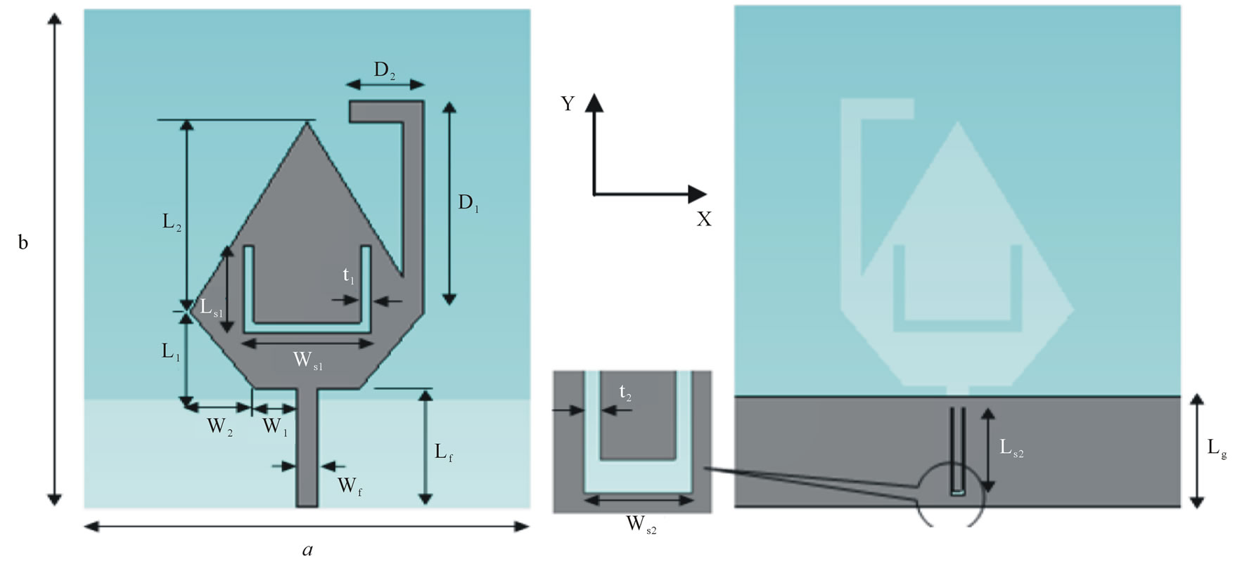
Figure 1 shows the geometry of the antenna A which is fed by a microstrip line and built on a FR-4 substrate with 42 × 46 mm2 surface area, 1mm thickness with relative permittivity of 4.4 and loss tangent of 0.02. There is no ground metallization underneath the radiator for proper operation.
The antenna provides a dual-band operation due to two different radiating elements. The UWB element of rhomboidal geometry is responsible for the 3.1 - 10.6 GHz UWB band and exhibits tapered smooth transitions for the wideband response and improved matching at higher frequencies.
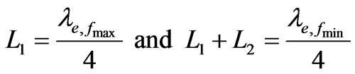
The design of the UWB rhomboid antenna starts with choosing L1, L2, and W1. L1 and L2 are critical parameters associated with the upper and lower operating frequencies of the antenna. W1, on the other hand, is a key parameter to maintain good input impedance matching for the frequency range of 2.4 - 11 GHz. Accordingly, L1 and L2 are selected to have a reasonable return loss at fmin = 3.1 GHz and fmax = 10.6 GHz, which are the lower and upper ends of the UWB band [12]. A good starting point for these dimensions is as follows:
The geometrical parameters have been optimized by using two commercial EM simulators based on Finite Element Method (FEM) and the second simulator based on Finite Integration Technique (FIT). Table 1 shows the dimensions of antenna A.
2.2. Antenna B Design
Figure 2 shows the second proposed antenna B. It has the same basic structure of antenna A to give the operating frequency range of 2.4 - 11 GHz with a U-shaped slot in the ground plane and a H-shape slot in the radiating
 (a) (b)
Figure 1. Geometry of proposed antenna A, (a) Top view; (b) Back view.
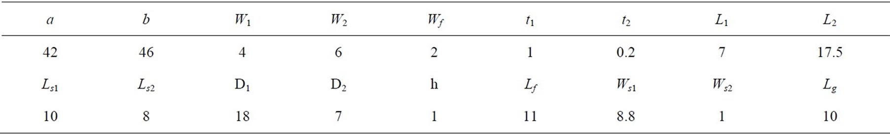
Table 1. Dimensions of antenna A (all dimensions in mm).
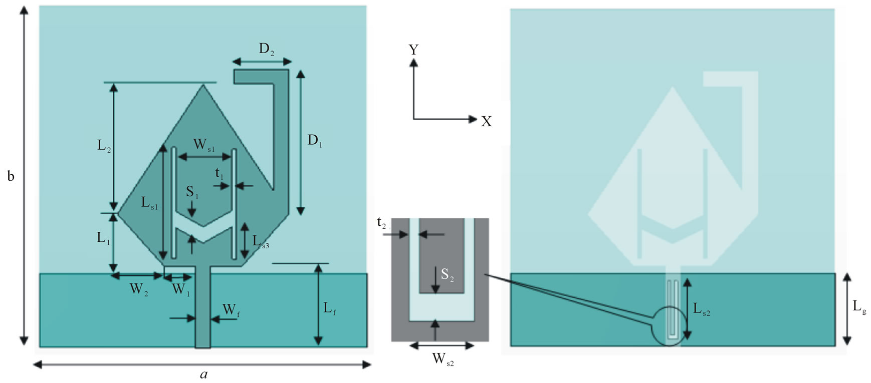
Figure 2. Geometry of proposed antenna B.
patch. The geometrical parameters have been optimized by using two commercial EM simulators based on Finite Element Method (FEM) and the second simulator based on Finite Integration Technique (FIT) as shown in Table 2.
3. Numerical Results
3.1. Numerical Results of Antenna A
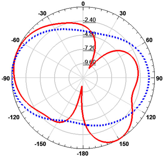
Figures 3 and 4 show the simulated return loss (RL) and voltage standing wave ratio (VSWR) of the proposed antenna before and after adding slots using FEM and FIT simulators versus the operating frequency. Good agreement is obtained. A U-shape slot is embedded at the center of the ground plane forming DGS which can notch the WLAN frequency band at 5.2 - 5.8 GHz. On the other hand, the U-shaped slot etched on the radiating patch can notch the 3.3 - 4 GHz band for WiMAX. The figures show that RL < −10 dB and VSWR < 2 in the operating bands of Bluetooth and UWB except the notched bands for WiMAX and WLAN. Figure 5 shows the radiation patterns at 2.4, 3.5, 5.5 and 9 GHz. It is found that, the antenna gives nearly omnidirectional pattern in xz-plane as required at Bluetooth and UWB bands. Figure 6 present the antenna gain versus the frequency. The gain has acceptable flatness in the operating bands
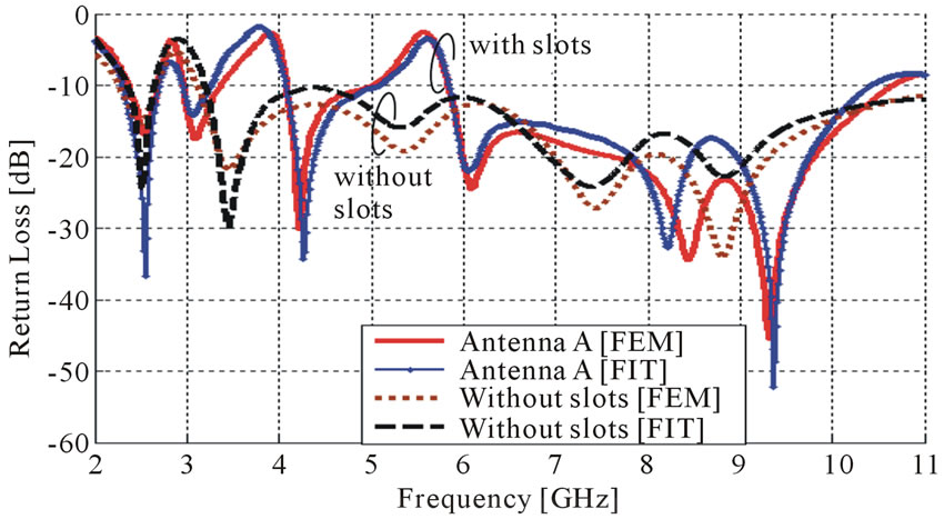
Figure 3. The simulated return loss of antenna A before and after adding slots using FEM and FIT simulators.
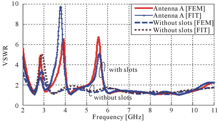
Figure 4. The simulated VSWR of antenna A before and after adding slots using FEM and FIT simulators.
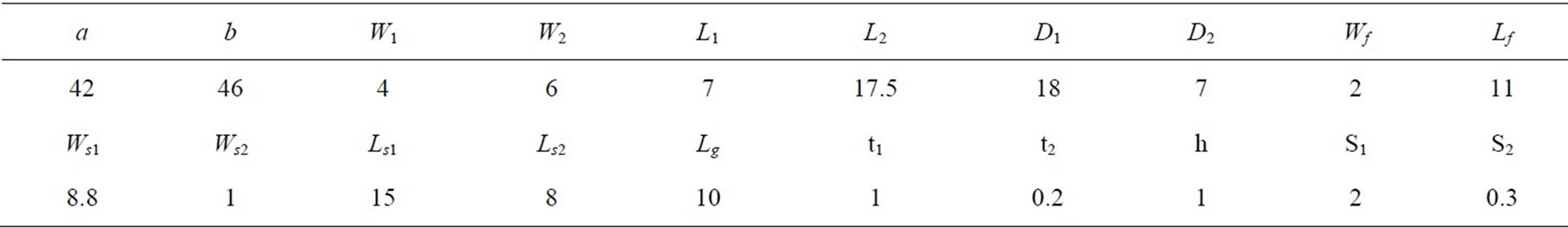
Table 2. Dimensions of antenna B (all dimensions in mm).
 (a)
(a)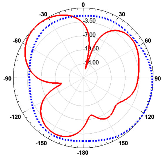 (b)
(b)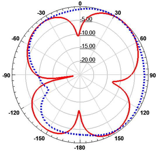 (c)
(c)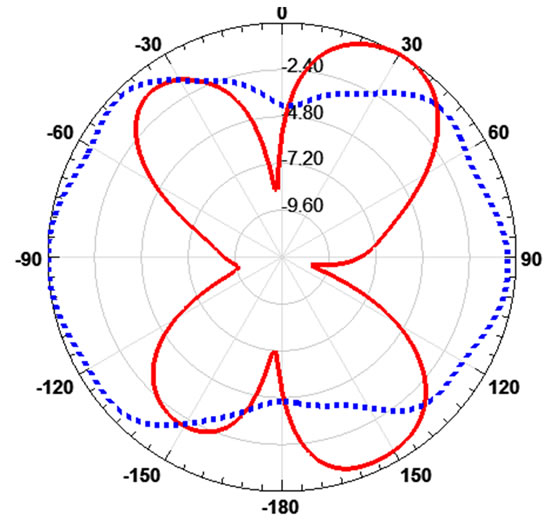 (d)
(d)
Figure 5. The radiation patterns of antenna A in xz-plane at: (a) 2.4 GHz; (b) 4.2 GHz; (c) 5.5 GHz; (d) 9 GHz.
and it decreases at the notched bands where the gain is −2.2 dB at 3.6 GHz and −9.8 dB at 5.7 GHz.
3.2. Numerical Results of Antenna B
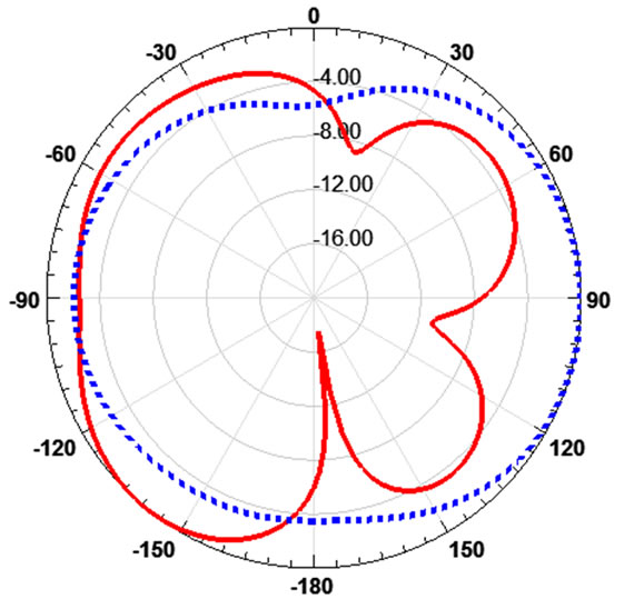
Figures 7 and 8 show the simulated return loss and voltage standing wave ratio (VSWR) of the antenna B before and after adding slots using FEM and FIT simulators. Good agreements are obtained. The −10 dB band increased from 3.1 GHz to 13.5 GHz. The U-shape slot is embedded at the center of the ground plane forming DGS which can notch the WLAN frequency band at 5.2 - 5.8 GHz. The H-shaped slot etched on the radiation patch may be regarded as two slots: an upper U-shaped slot and a lower C-shaped slot. The upper U-shaped slot can notch the 3.3 - 4 GHz band for WiMAX, and the lower C-shaped slot can notch the 7.2 GHz for some C-band satellite communication systems. Figure 9 shows the radiation patterns at 2.4, 4.2, 7.2 and 9 GHz. The antenna gives nearly omnidirectional pattern in xz-plane required at Bluetooth and UWB bands.
The antenna gain in the entire operating band for Antenna B is shown in Figure 10. The gain has acceptable flatness in the operating bands and it decreases at the notched bands the gain is −2.2 dB at 3.6 GHz, −9.8 dB at 5.7 GHz and −2.2 dB at 7.2 GHz.
Figure 11 shows the return loss versus the frequency for antenna B with varying the length Ls3 of the H-shape slot. The central WiMAX band and central of C-band rejection can be tuned by changing the dimensions of H-shape slot by changing the parameter LS3 which changing the dimension of the upper U-shaped slot and a lower C-shaped slot without changing WLAN band
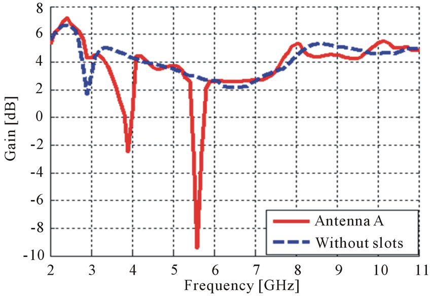
Figure 6. The gain of the antenna A versus the frequency before and after adding using FEM simulator.
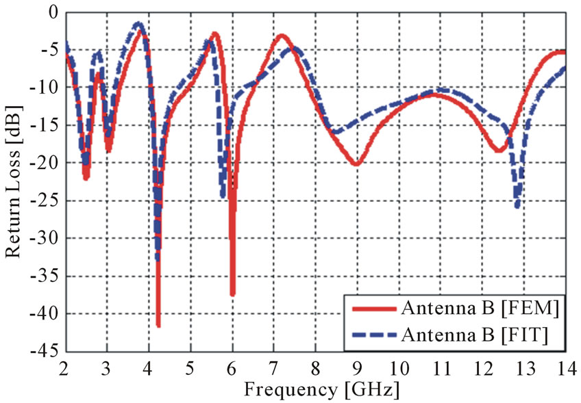
Figure 7. The simulated Return Loss (RL) of the antenna B using FEM and FIT simulators.
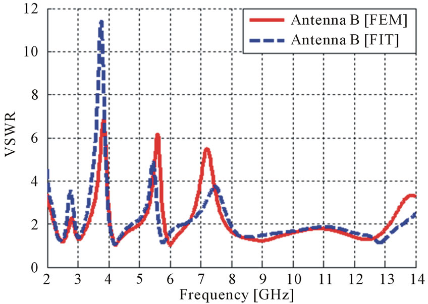
Figure 8. The simulated VSWR of the antenna B using FEM and FIT simulators.
notch and the bandwidth of the antenna.
Finally the comparison between antenna A and antenna B is shown in Figure 12. Double notched bands at 3.3 - 4 GHz for WiMAX and 5.2 - 5.8 GHz for WLAN
 (a)
(a) (b)
(b)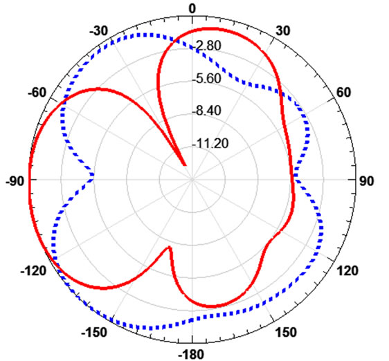 (c)
(c)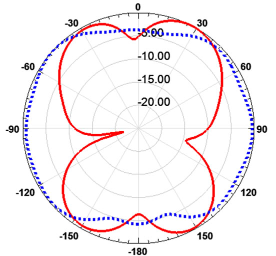 (d)
(d)
Figure 9. The radiation pattern of Antenna A in xz-plane at: (a) 2.4 GHz; (b) 4.2 GHz; (c) 7.2 GHz; (d) 9 GHz.
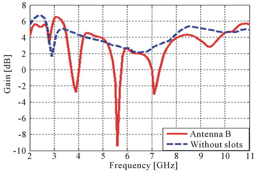
Figure 10. The gain of antenna B versus the frequency before and after adding using FEM simulator.
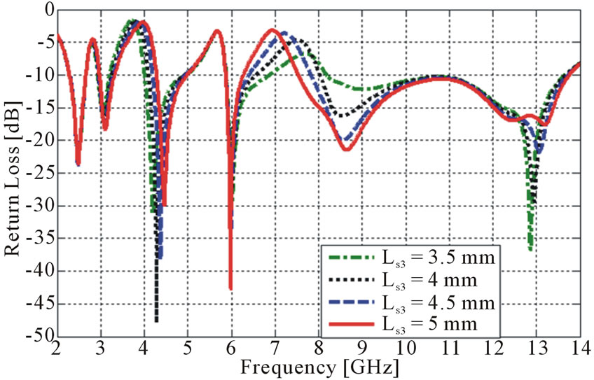
Figure 11. Simulated return loss for different position of H-slot.

Figure 12. Simulated return loss for antenna A and antenna B.
are achieved in antenna A by using U-shape slot in the radiating patch and U-shape slot in the ground plane but in antenna B tri-notched bands at 3.3 - 4 GHz, 5.2 - 5.8 GHz and 6.7 - 7.8 GHz for C-band satellite communication are achieved by using H-shape slot in radiating patch and U-shape slot in the ground plane. Antenna B has wider bandwidth from 2.4 GHz to 13.6 GHz.
4. Conclusions
Two compact printed Bluetooth and UWB antennas with dual band and tri-band rejection characteristic are presented. Two different types of slots, a U-shaped slot and a H-shaped slot etched on the radiating patch plus the U-shape slot in the ground plane, are used to obtain two and three notched bands respectively, which means exemption from interference with existing WiMAX, WLAN, and C-band satellite communication systems. The proposed antennas yield an impedance bandwidth of UWB (3.1 - 10.6 GHz) and at the Bluetooth frequency band with Return loss < −10 dB and VSWR < 2, except the notched bands. The omnidirectional radiation patterns are very stable across the Bluetooth and UWB bands.
REFERENCES
- A. A. Eldek, A. Z. Elsherbeni and C. E. Smith, “Rectangular Slot Antenna with Patch Stub for Ultra Wideband Applications and Phased Array Systems,” Progress in Electromagnetic Research, Vol. 53, 2005, pp. 227-237. doi:10.2528/PIER04092701
- S. H. Choi, J. K. Park, S. K. Kim and J. Y. Park, “A New Ultra-Wideband Antenna for UWB Applications,” Microwave and Optical Technology Letters, Vol. 40, No. 5, 2004, pp. 399-401. doi:10.1002/mop.11392
- M. Gopikrishna, D. D. Krishna, C. K. Anandan, P. Mohanan and K. Vasudevan, “Design of a Compact SemiElliptic Monopole Slot Antenna for UWB Systems,” IEEE Transactions on Antennas and Propagation, Vol. 57, No. 6, 2009, pp. 1834-1837. doi:10.1109/TAP.2009.2015850
- R. A. Al Essa, “Analysis of Ultra Wide-Band Metal Plate Monopole Antenna Using Finite Difference Time Domain (FDTD) Method,” MSc. Thesis, Helwan Univesity, Helwan, 2010.
- Q.-X. Chu and Y.-Y. Yang, “3.5/5.5 GHz Dual BandNotch Ultra-Wideband Antenna,” Electronics Letters, Vol. 44, No. 3, 2008, pp. 172-174. doi:10.1049/el:20083095
- K. Yin and J. P. Xu, “Compact Ultra-Wideband Antenna with Dual Band-Stop Characteristic,” Electronics Letters, Vol. 44, No. 7, 2008, pp. 453-454. doi:10.1049/el:20080484
- J.-Y. Deng, Y.-Z. Yin, Sh.-G. Zhou and Q.-Zh. Liu, “Compact Ultra-Wideband Antenna with Tri-Band Notched Characteristic,” Electronics Letters, Vol. 44, No. 21, 2008, pp. 1231-1233. doi:10.1049/el:20081660
- Q. Zhao, S.-X. Gong, W. Jiang, B. Yang and J. Xie, “Compact Wide-Slot Tri-Band Antenna for WLAN/WiMAX Applications,” Progress in Electromagnetic Research Letters, Vol. 18, 2010, pp. 9-18. doi:10.2528/PIERL10081601
- S. H. Zainud-Deen, R. A. Al-Essa and S. M. M. Ibrahem, “Ultrawideband Printed Elliptical Monopole Antenna with Four Band-Notch Characteristics,” IEEE Antennas and Propagation Society International Symposium (APS/ URSI), Toronto, 11-17 July 2010.
- C. Kim, H. Ahn, J. Kim, X. Cheng and Y.-K. Yoon, “A Compact 5 GHz WLAN Notched Bluetooth/UWB Antenna,” IEEE Antennas and Propagation Society International Symposium (APS/URSI), Toronto, 11-17 July 2010.
- S. K. Mishra, R. Gupta, A. Vaidya and J. Mukherjee, “Printed Fork Shaped Dual Band Monopole Antenna for Bluetooth and UWB Applications with 5.5 GHz WLAN Notched Characteristics,” Progress in Electromagnetic Research C, Vol. 22, 2011, pp. 195-210. doi:10.2528/PIERC11053006
- B. S. Yildirim, B. A. Cetiner, G. Roqueta and L. Jofre, “Integrated Bluetooth and UWB Antenna,” IEEE Antennas and Wireless Propagation Letters, Vol. 8, 2009, pp. 149-152. doi:10.1109/LAWP.2009.2013371
- P. Wiggers, “Nonlinear Finite Element Methods,” SpringrVerlag, Berlin, 2008.
- D. V. Hutton, “Fundamentals of Finite Element Analysis,” McGraw-Hills Companies, New York, 2004
- T. Welinad, “A Disretization Method for the Solution of Maxwell’s Equations for Six Component Fields,” Electromagnetics and Communications AEU, Vol. 31, No.3, 1977, pp. 116-120.
- R. Marklin, “The Finite Integration Techniques as a General Tool to Compute Acoustic, Electromagnetic, Elastodynamic, and Coupled Wave Fields,” IEEE Press, New York, 2002, pp. 201-244.