Journal of Electromagnetic Analysis and Applications
Vol. 3 No. 5 (2011) , Article ID: 5021 , 8 pages DOI:10.4236/jemaa.2011.35024
The Ultra Wide Band Radar System Parameters in Medical Application
![]()
6’Tel Research Unit Higher School of Communications of Tunis, Sup’Com Carthage University, Tunisia.
Email: elmissaoui.enit@gmail.com
Received February 10th, 2011; revised March 21st, 2011; aceepted March 28th, 2011.
Keywords: UWB, Radar, Medical Imaging, Human Body Model
ABSTRACT
In this work, an Ultra Wide Band (UWB) radar system is proposed in an attempt to take a medical image of each human body layer. In fact, this system consists of sending an electromagnetic pulse and analyzing the echo reflected by the human body tissue. In order to realize this system, the parameters which enable us to optimize the functionality of our radar are computed. Indeed, we fixed a frequency range, incident angle, pulse repetition frequency, the power and the antenna deployed by the UWB radar system in medicine. As well as, a human body model is presented in order to have practical results.
1. Introduction
There have been growing interests in recent years’ research the Ultra Wide Band (UWB) technology and radar system. The radar is built in a wide variety and for a large number of different applications. In the early years, Radar system was limited to military and a few civil applications like navigation and vehicle speed detection.
Nowadays, the Radar system is used in many applications such as in the GPR (Ground Penetration Radar). In this paper, the UWB radar system is to be used in a medical application. In fact, it is possible to employ this system to take a medical image of the human body. Moreover, this image enables doctors to diagnose the human body in an attempt to detect anomalies like cancer.
To meet such an aim, the system UWB radar block diagram is suggested and used in a medical image in the first section. Then, the parameters of the UWB radar system in medicine are fixed, in the second section. In fact, a human body model as used in this application is presented. Similarly, the reflection and transmission coefficients of each human body layer for two types of incidence (normal and oblique) are computed. Moreover, the frequency range used by our system is fixed in the third section. Then, the travel time put by each human body echo is estimate. Besides, the pulse repetition frequency needed in this application is calculated. While in the fourth section, the antenna deployed by our radar is designed. Furthermore, the antenna position needed to capture each echo reflected by the human body structure is computed. Finally, the results in the conclusion are discussed.
2. The UWB Radar System
The UWB radar system uses radiated and reflected electromagnetic waves to detect, locate and identify a certain target.
A UWB radar system offers many benefits over continuous wave radars [1]:
• Due to a very high down-range resolution, a target can be precisely located;
• A large bandwidth allows a better separation between targets and a clutter;
• It possesses a good immunity against a multipath interference, which is very strong within buildings and collapsed buildings;
• Multiple targets can be resolved.
Moreover, this system can be used in the medical application. In fact, the electromagnetic pulses generated by the UWB radar are able to explore human body. Then, the human body layer has got electric characteristics which make differentiate between each echo reflected by the human body structure.
Our UWB radar system consists of sending an electromagnetic pulse and listens to the echo reflected by each human layer. For this reason, it is possible to take a photo of each human body layer after analyzing his reflected pulse.
In this part, a generic radar block diagram is to be proposed.
Figure 1 shows the radar system block diagram. For the normal incidence of the electromagnetic pulse, the same antenna for both radiation and reception is used. But, for the oblique incident an antenna for each human body layer is used and the antenna position must be studied.
Then, this proposed system presents many advantages better than other medical imaging systems used until now such as:
• Contrast X-rays
• Computerized tomography scanning
• Magnetic resonance imaging (MRI)
• Positron emission tomography
• Radionuclide scanning
• Single photon computerized tomography
• Ultrasound and X-rays All these technologies suffer from many disadvantages. Most of them need to expose human body to the strong electromagnetic radiation for long time that presents a potential damage to the cell. This can strengthen the risk of cancer in patient’s later life. In the same vein, the repeated use of this kind of system is not safe for the human health. However, the UWB radar system uses an ultra short pulse that minimizes the electromagnetic effect. Similarly, it has a very high image resolution and a good capacity of penetration in the human body biological structure. And, the UWB radar imaging is very fast compared to all other systems. For example the MRI processes can take 30 minutes.
In addition, this system is not expensive like MRI system. Nonetheless, the technique of the realization of this equipment is not complicated akin to other systems.
Although the UWB radar is a new system for medical application it tends to ignore other techniques in the future.
3. The Human Body Model
Each human body layer can be presented by a good di-
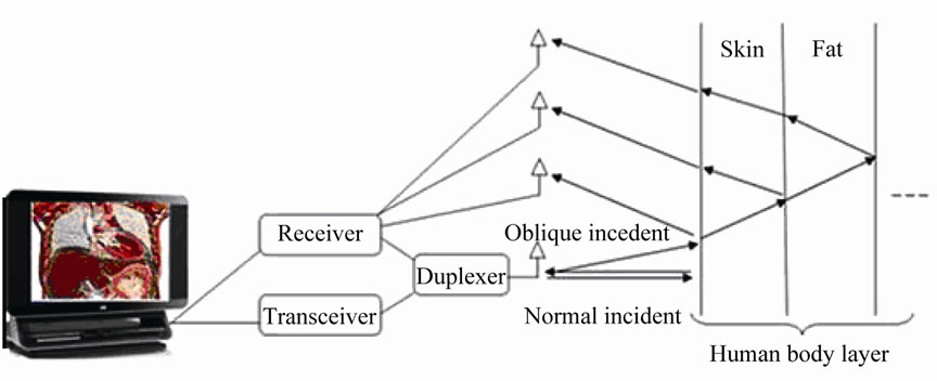
Figure 1. The radar block diagram.
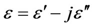
electric with certain characteristics that vary according to the frequency of the incident wave [2-5]. Moreover, the permittivity of the human body structure is complex and can be expressed by [2-5]:
 (1)
(1)
where  is the relative permittivity of the biological tissue and
  the out-of-phase loss factor associated with it such as in:
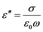 (2)
(2)
The permittivity is increased with the frequency in all the layers of the human body. But the conductivity is decreased with the frequency [1].
The propagation constant of each human body layer can be written as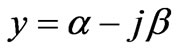 ; where the attenuation constant
 ![]() and propagation constant
and propagation constant  can be written as follows [6]:
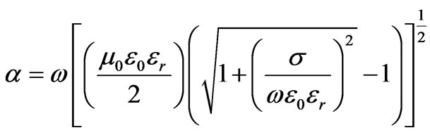 (3)
(3)
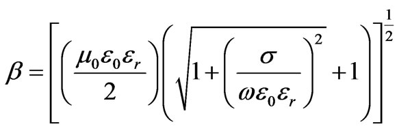 (4)
(4)
where:
![]() : The Angular frequency
: The Angular frequency
 : The Free space permittivity.
 : The Free space electromagnetic permeability.
![]() : The Relative conductivity of the human body layer.
: The Relative conductivity of the human body layer.
 : The Relative permittivity of the huamn body layer.
The skin depth ![]() is given
is given  by as follows [6]:
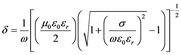 (5)
(5)
In this case, the human body can be modeled by a multilayer good dielectric that is composed of planar layers skin, fat, muscle, bone and lung tissue. The human body model is shown in Figure 2.
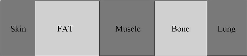
Figure 2. Layered tissue model.
4. Reflection and Transmission Coefficients
In this section, the interaction of the human body layer and electromagnetic wave is discussed. At this statement, two kinds of incident electromagnetic incidents are possible: an oblique incident and a normal incidence.
Each type of incident will be further examined.
4.1. Normal Incidence
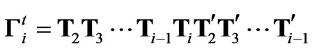
When the normal incident electromagnetic wave encounters a boundary, it will be subdivided into reflected and transmitted parts. The total field that is reflected by the  layer can be expressed by [1]:
 (6)
(6)
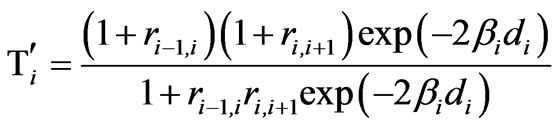
where  and
and  represent, respectively, the total field transmission and reflection by the
  layer for an incident wave from the left they can be expressed by [1]:
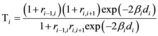 (7)
(7)
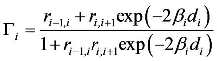 (8)
(8)
The reflection coefficient of the electromagnetic wave by the interface interlayer i/i+1 is given by [7]:
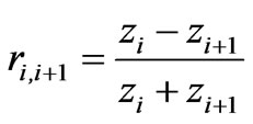 (9)
(9)
Here, ![]() presents the impedance of the ith layer is written as [7]:
presents the impedance of the ith layer is written as [7]:
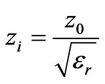 (10)
(10)
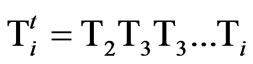
The total field transmission by the ith layers for an incident wave from the right can be expressed by [1]:
 (11)
(11)
The total electromagnetic field transmission by the ith layer is represented by [1]:
 (12)
(12)
4.2. Oblique Incidence
The same for the oblique incidental pulse, it will be divided into parts reflected and transmitted. In Order to examine the reflection and transmission coefficients, the electromagnetic wave must be decomposed into parallel and perpendicular parts. The total reflected and transmitted field will be the sum of the two parts.
4.2.1. The Perpendicular Polarization
The reflection coefficient of i/i+1 interface is mentioned in the following expression by [8]:
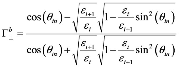 (13)
(13)
The transmission coefficient of i/i+1 interface can be presented by [8]:
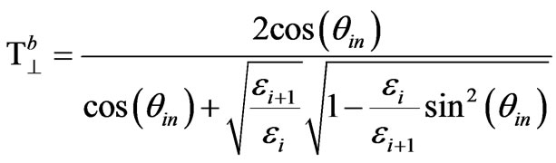 (14)
(14)
where:
 : The Incident angle.
![]() ,
, : The Permittivity respectively of ith layer and i+ith layer.
4.2.2. The Parallel Polarization
The reflection coefficient of i/i+1 interface is mentioned in the following expression by [9]:
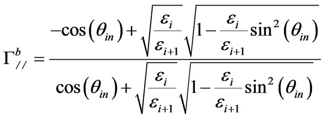 (15)
(15)
The transmission coefficient of i/i+1 interface can be presented by [8]:
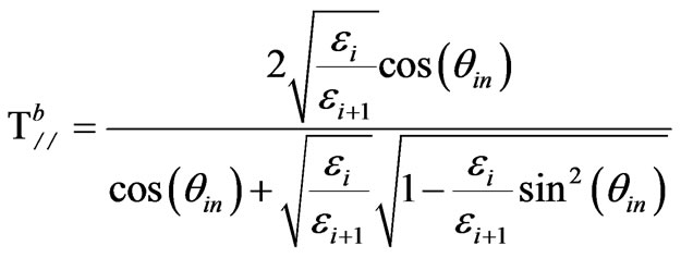 (16)
(16)
5. The Frequency Range
The electromagnetic compatibility (EMC) and the electromagnetic interference (EMI) must be considered as the UWB radar system design to elude the potential interference problem. Moreover, our radar system is used in the medical application (indoor). Then, the FCC allocated frequency ranges from 3.1GHz to10.6GHz to UWB system. The emission limit for the system imagining and indoor system is limited to –41.3DBm The radar system can be operated with all frequency. In this part, a frequency range that enables us to optimize our UWB radar system in medicine applications is to be fixed. In accordance with the previous section, the human body is composed of many parallel layers. This encourages us to choose a frequency range that discards the mutual influence of the layer that composes the human body.
According to [1], the mutual layer influence in the frequency range 4GHz-6GHz can be neglected.
Actually, our goals consist of designing and fixing the parameters of the UWB radar in medicine.
For this reason, the condition of the UWB system that imposes the fractional bandwidth FB which must be greater than 0.25 must be respected [9].
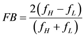 (17)
(17)
where:
 = the high frequency
 = the low frequency If we use the frequency range 4 GHz - 6 GHz, our system has an FB greater or equal to 0.4 that respects the UWB system definition.
6. The Incidence Angle
The reflection and transmission coefficients are complex quantities. Then, these values depend on the frequency and incidence angle. For this reason, an angle that enables to maximize both coefficients reflection and transmission is to be found. In fact, the angle that optimizes the reflection coefficient is the critical angle. Moreover, the angle that maximizes the transmission coefficient is the Brewster angle. When examined the results presented by Gabriel in [3-5,10], can prove that the electric characteristic of the human body layer are changed slightly according to the frequency in the 4 GHz - 6 GHz frequency range.
When the obtained result in [8] is taken into consideration, a study of the parallel polarization case can be proposed. In fact, they have the same critical angle. Besides, the Brewster angle perpendicular polarization doesn’t have a solution.
6.1. The Brewster Angle
In this part, the condition under which the reflection coefficient for parallel polarization will disappear is examined, the set  is set up equal zero; that is
 (18)
(18)
The Brewster angle  is given by [9]:
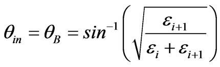 (19)
(19)
The reflected echo is exploited by our radar system in order to make the human body layer photo. For this motive, interest must be given to the incident angle that enables us to optimize the reflection coefficient better than the transmission coefficient. In the next subsection, the incident angle is to be computed and made capable to maximize the echo of each human body structure.
6.2. A Critical Angle
In this case, the same procedure is repeated and used in a perpendicular polarization.
 (20)
(20)
The expression for the critical angle  is the same angle as that for a perpendicular polarization as given by [8]:
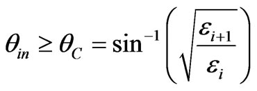 (21)
(21)
When the Equation (21) is examined, the critical angle that exists only if the wave propagates from a denser to a less dense layer is confirmed. With this intention, it is possible to compute the critical angle only for both layers which are Skin and Bone layer. But for the other human body layer, it is more interesting to use a normal incidence because the maximum of the reflection coefficient exists with this kind of incidence. In fact, Figure 3 illustrates that the incident angle must be greater than 8.05° for the Skin layer. Moreover, Figure 4 shows that for the Bone layer, we must use an incident angle greater than 18.4°.
7. The Return Time of the Reflected Echo of the Human Body Layers
In addition to the Snell law, the reflected angle is equal to the incident angle. Then, the receptive antenna and transceiver antenna must be in the same position in an attempt to capture the reflected echo. For this reason, the same antenna is used for reception and emission. In that case, the reflected echo of each human body layer is discerned by the arrival time at the receiver. Now, the travel
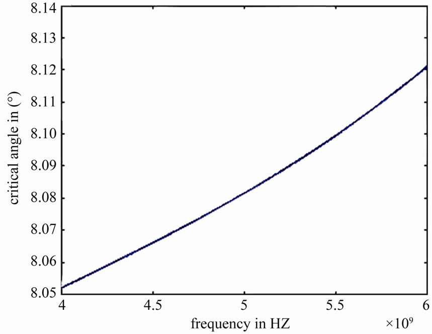
Figure 3. Critical angle of the Fat layer.
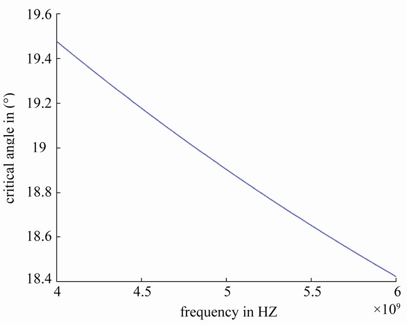
Figure 4. The Critical angle of the Bone layer.
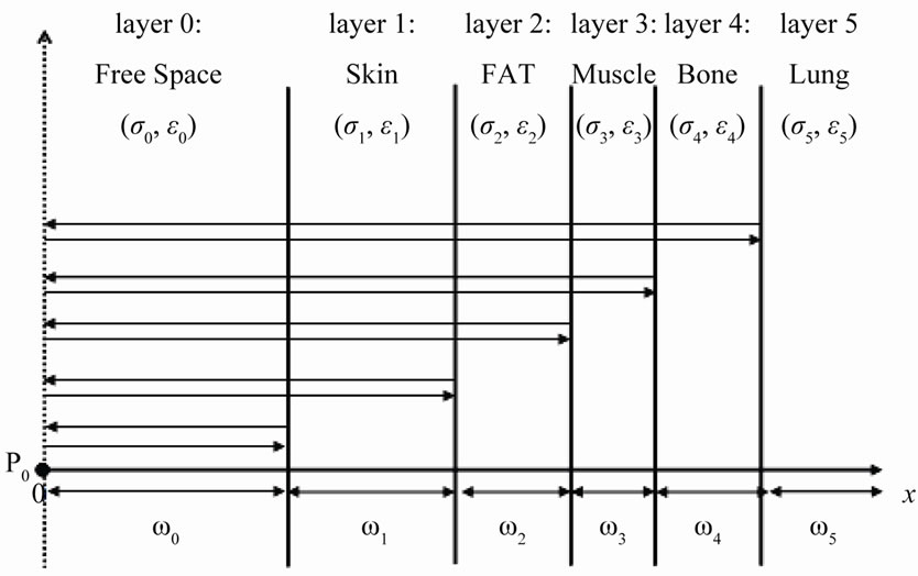
Figure 5. An outside distance crossed by each echo of the human body layer at a normal incidence.
time put by each echo for normal incidence is to be calculated.
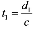
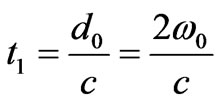
The echo reflected by the first layer crossed the free space twice, for this reason, the echo time travel t1 can be expressed by:
 (22)
(22)
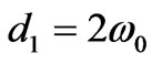
where C is the speed of light in the free space and d1 is the distance crossed by the echo reflected by the Skin layer. It can be expressed by.
 (23)
(23)
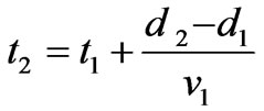
For the second layer, the echo crosses the layer of the free space twice as well as the second layer with this intention, the time put by this echo can be expressed by:
 (24)
(24)
where: 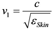 The velocity into the Skin layer [11].
d2 The distance crossed by the echo reflected by the Fat layer and it is mentioned in the following Expression by:
 (25)
(25)
In the same way, for the layer three, t3 can be written as:
 (26)
(26)
where:
 present the velocity into the Fat layer.
d3 the distance crossed by the echo reflected by the Muscle layer and it is given by:
 (27)
(27)
Which can be generalized by:
 (28)
(28)
where:
 is the velocity into the ith layer.
di is written as:
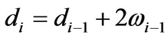 (29)
(29)
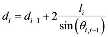
The case of the oblique incidence is studied deeply in [2]. In fact, the distance travelled by the echo of the layer can be expressed by:
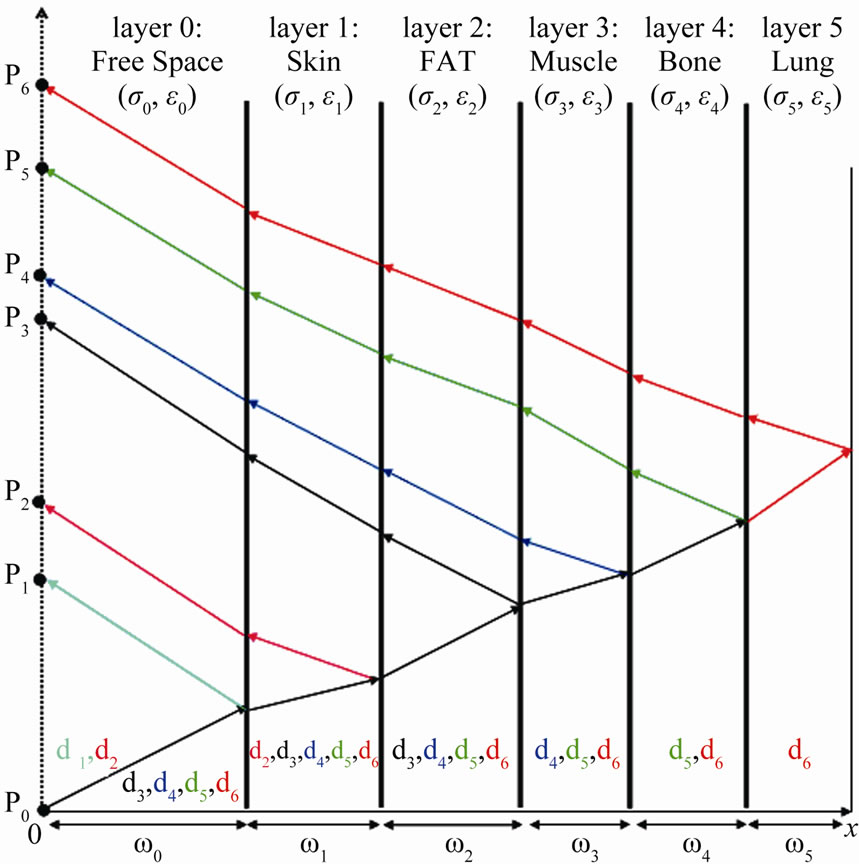
Figure 6. Outside, the distance di crossed by the layer echo at an oblique incident.
 (30)
(30)
The Figure 6 present the distance crossed by the ith echo.
8. Pulse Repetition Frequency (PRF)
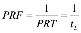
The PRT (Pulse Repetition Time) is the time from the beginning of one pulse to the beginning of the next.
The Pulse Repetition Frequency (PRF) is the number of radiation pulses issued by our UWB radar in one second. The PRF is mentioned in the following expression by:
 (31)
(31)
Our target is to fix parameters of the UWB radar system in medicine. In an attempt to realize this system, the PRF must be determined. In fact, the PRF is to be used in attempt to distinguish the several echo reflected by the human body.
The human body layers are different not only in terms of the electric characteristics but also in the width. This generates a variety of the echo travel time. On this basis, a PRF is to be computed for each human body layer. In order to illustrate results, a frequency equal to 5 GHz is used for two reasons:
• The mutual influence is discarded in this frequency.
• 5 GHz is the central frequency of our frequency range used in the UWB radar.
8.1. Skin
The permittivity of the Skin layer is better than the permittivity of the free space. Then, a normal incident is used in an attempt to capture the Skin image.
 (32)
(32)
where  cm the distance that separates our radar system and the Skin layer (width of the free space layer).
The travel time of the echo reflected by the skin layer is equal to 333.3333 ps.
 (33)
(33)
In an attempt to detect the Skin echo, we must use a PRF equal or less than 3GHz.
8.2. Fat
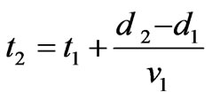
The permittivity of the Skin layer is better than the permittivity of the Fat layer. Then, we use an Oblique incidental pulse in an attempt to capture the Skin image. According to section 6 an Incident angle greater than 8.05° can be used. In our case, an incident angle equal to 45° is chosen in an attempt to illustrate practical results. The travel time put by the Fat layer echo can be expressed by:
 (34)
(34)
where:
t1: the travel time of the Skin layer echo d1: the distance crossed by the Skin echo d2: the distance crossed by the Fat echo v1: the wave velocity in the Skin layer
 (35)
(35)
The skin echo travel time is equal to 523.6071ps. Then, the PRF should be equal or less than 1.9098 GHz
8.3. Muscle
For the same reason and like the Skin layer, the permittivity of the Muscle layer is better than the permittivity of the Bone layer, a normal incident pulse must be used. Consequently, the travel time of the Muscle skin layer can be expressed by:
 (36)
(36)
where: v2 is a wave velocity in the Fat layer The time put by the Muscle echo layer is equal to 961.88ps. Then, the PRF must be equal or less than 1.0396GHz.
 (37)
(37)
8.4. Bone
For the Bone layer, the critical angle exists and must be greater than 19.6° for each frequency in 4GHz- 6GHz. In our case, an incident angle equal to 45° is used. The travel time of the Bone layer echo can be expressed by [2]:
 (38)
(38)
where: v3: the wave velocity in the Muscle layer
 (39)
(39)
The echo travel time of the bone layer is equal to 1.0357 103 ps. For this reason, a PRF less or equal to 0.96556GHz is used.
8.5. Lung
The Lung is the last layer of our human body model used in this paper. Then, the Lung echo crossed all previous layers time twice. Moreover, the Lung permittivity is greater than the Bone permittivity. For this reason, a normal incidence is used. The echo travel time of the Lung layer can be presented by
 (40)
(40)
where: v3 is the wave velocity in the Bone layer
 (41)
(41)
The echo travel time of the bone layer is equal to 6.1267 103ps. Therefore, a PRF less or equal to 0.16322 GHz is used.
9. The Antennas
Our Radar system must deploy an antenna to radiate and receive electromagnetic pulse. The antenna is the transducer between the system and the free space. Moreover, the antenna is an important parameter for a good result.
In this section, the antenna employed by the UWB radar system is designed. In fact, the antenna must be radiated in 4 GHz - 6 GHz frequency range. The central frequency of our system is equal to 5 GHz.
In our case, a patch circular antenna that has a radius equal to 8.17 mm is used. Figure 7 shows the return loss of our antenna. This antenna has a return loss equal to –17 DBI at a frequency of 5GHz.
Figure 8 present the pattern radiation at 5 GHz.
In an attempt to optimize our radar system, a strategic antenna position must be found.
For the Skin, Muscle and Lung layers, normal incidence is used. For this reason, the same antenna to radiate or receive an electromagnetic pulse is exploited. But, for the Fat and Bone layer, an oblique incidence is used. In this case, the antenna position is computed for each layer.
Table 1 illustrates the emplacement of the receiver’s antenna of each echo layers for an oblique incidence impulsion  = 45° and a normal incidence at a frequency
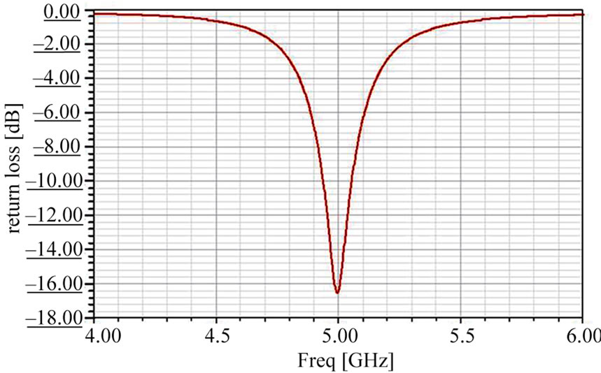
Figure 7. The return loss of the antenna.
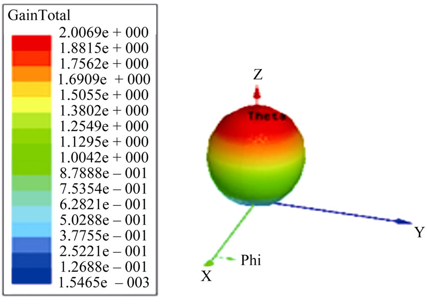
Figure 8. The three-dimensional of the pattern radiation at 5 GHz.
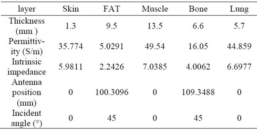
Table 1. Antenna position of each echo layer.
of 5 GHz [2].
10. Conclusions
In this paper, a new radar system that enables doctors to diagnose the human body in order to solve many human health problems is proposed.
After providing a design of the UWB radar system, a human body model is presented. Then, the parameters of our UWB radar in medicine are fixed. In an attempt to optimize our system, we must carefully choose the characteristics of the radar system. In fact, the radar system deploys a 4GHz-6GHz frequency range. Then, this system uses two kinds of incidences:
• A Normal incidence for the Skin, Muscle and Lung layers.
• An Oblique incidence that is equal to 45°for the Fat, Bone layers.
Furthermore, a particular study accorded to the reflection and transmission coefficients.
Moreover, our radar system uses a unique Pulse Frequency Repetition (PRF) for each human body layer.
Similarly, an antenna’s position that enables us to capture the echo reflected by the human body tissue is computed.
REFERENCES
- E. Taoufik, S. Nabila and B. Ridha, “The Reflection of Electromagnetic Field by Body Tissue in the UWB Frequency Range,” IEEE International Radar Conference, Washington DC, 10-14 May 2010, pp. 1403-1407.
- E. Taoufik, S. Nabila and B. Ridha, “New Radar System in Medicine,” The 2010 European Signal Processing Conference (EUSIPCO-2010), 2010.
- C. Gabriel, “A Compilation of the Dielectric Properties of Body Tissues at RF and Microwave Frequencies,” Radiofrequency Radiation Division, Brooks AFB, San Antonio, Contract AL/OE-TR-1996-0037, 1996.
- C. Gabriel, S. Gabriel and E. Corthout, “The Dielectric Properties of Biological Tissues: I. Literature Survey,” Physics in Medicine and Biology, Vol. 41, No. 11, November 1996, pp. 2231-2249.
- S. Gabriel, R. W. Lau and C. Gabriel, “The Dielectric Properties of Biological Tissues: II. Measurements on the Frequency Range 10 Hz to 20 GHz,” Physics in Medicine and Biology, Vol. 41, No. 11, November 1996, pp. 2251- 2269.
- Gang Kang and Om P. Gandh, “Effect of Dielectric Properties on the Peak 1- and 10-g SAR for 802.11 a/b/g Frequencies 2.45 and 5.15 to 5.85 GHz,” IEEE Transactions on Electromagnetic Compatibility, Vol. 46, No. 2, May 2004, pp. 268-274. doi:10.1109/TEMC.2004.826875
- G. Varotto and E. M. Staderini, “A 2D Simple Attenuation Model for EMWaves in Human Tissues: Comparison with a FDTD 3D Simulator for UWB Medical Radar,” Proceedings of 2008 IEEE International Conference on Ultra-Widebanb (ICUWB2008), Hannover, September 2008, pp. 1-4.
- C. Balanis, “Advanced Engineering Electromagnetics,” John Wiley & Sons, Hoboken, 1989.
- J. D. Taylor, “Introduction to Ultra-Widband Radar System,” Retierd, US Air Force, CRC Press, 1995.
- S. Gabriel, R. W. Lau and C. Gabriel, “The Dielectric Properties of Biological Tissues: III. Parametric Models for the Dielectric Spectrum of Tissues,” Physics in Medicine and Biology, Vol. 41, No. 11, November 1996, pp. 2271-2293.
- S. Coen, “Inverse Scattering of a Layered and Dispersionless Dielectric Half-Space, Part I: Reflection Data from Plane Waves at Normal Incidence,” IEEE Transactions on Antennas and Propagation, Vol. ap-29, No. 5, September 1981. pp. 26-32.