Journal of Electromagnetic Analysis and Applications
Vol. 2 No. 9 (2010) , Article ID: 2766 , 14 pages DOI:10.4236/jemaa.2010.29069
Elevated Ferrite Film Circulator with Different Permittivities for Layers: An Analytical Expression for the Input Conductance Employing Perturbation Method
![]()
1Electrical and Computer Engineering Department, Northeastern University, Boston, USA; 2Electrical Engineering Department, Sharif University of Technology, Tehran, Iran.
Email: rashiditarha.a@neu.edu, banai@sharif.ir
Received July 9th, 2010; revised July 31st, 2010; accepted July 31st, 2010
Keywords: Elevated Ferrite Circulator, Perturbation Integral, Splitting Factor, Dipolar Resonant Frequencies
ABSTRACT
The main idea of this paper is to find an analytical formula for the input conductance of an elevated ferrite film circulator to match it systematically to the desired matching network. For solving the ferrite loaded dielectric resonator included in stripline elevated ferrite film circulator, the off diagonal components of the permeability tensor are taken as the perturbation. The electromagnetic fields computations are done for unperturbed structure. The dipolar resonant frequencies corresponding to  harmonics of the resonant modes are then calculated using the perturbation integrals. The quality factor of the circulator is derived in terms of these dipolar resonant frequencies. Energy integrals are calculated to find the energy stored in the ferrite and dielectic layers. An analytical expression for the input conductance of the elevated ferrite film circulators is derived by using the quality factor and energy integrals. In this expression the ferrite and dielectric layers can have different permittivities. Some discussions about the effect of ferrite film thickness and permittivity mismatch on the bandwidth of the circulator are investigated by HFSS commercial software.
1. Introduction
Y-junction ferrite circulators are important devices in today microwave circuits and have been studied in literature in recent years [1-5]. This significance is initiated and spread out from the directional properties of ferrimagnetic devices allowing the control of microwave signals through a bias magnetic field [6]. Ferrite circulators with minimal size, weight and cost can be used in phased array antenna modules [7]. The other applications of Y-junction ferrite circulators can be in transmit receive functions where a shared antenna is required to be used for both transmission and reception of the signal [8].
Design theory for stripline Y-junction ferrite circulators was flourished by Bosma’s Green’s function [9]. According to Bosma’s assumptions the electric field is normal to the plane of the device ( direction) and the magnetic field is in the plane of the device (
 and
and  components ) [6]. The most important point in Bosma’s formulation is the relation between resonance (in which the peripheral of ferrite cylinders becomes PMC, perfect magnetic conductor) and Green’s function. If the off diagonal components of the permeability tensor of the ferrite, which are effectively shown by
 , go to zero, the ferrite becomes an isotropic medium. In this situation, just like a dielectric resonator, there is no difference between resonant frequency of clockwise mode, proportional to
 , and that of counterclockwise mode, proportional to
 , where
  is an integer number. As
  increases, the resonant frequencies
  and
and , which correspond to
  and
and  respectively, separate each other; That is why
  is called splitting factor. The variation of resonant frequencies versus splitting factor gives a mode chart for operating of a Y-junction ferrite circulator which is very well demonstrated in Bosma’s paper. Among these splitting modes, those which are proportional to
 , dipolar modes, catch the attention of circulator designers since they result in a minimum diameter of the ferrite cylinders [10]. According to Bosma’s mode chart, we can place the circulator in dipolar mode regime by choosing the value for operational frequency,
 , near the dipolar resonant frequencies,
  and
and , and far from other resonant frequencies
 , where
  for a given splitting factor,
 .
.
In addition to Bosma’s essential works about Y-junction ferrite circulators, the immense efforts of Fay and Comstock [10] are really praiseworthy. The main work of Fay and Comstock is the presentation of an equivalent circuit modeling the Y-junction circulator viewed from the input port when its other two ports are terminated to matched load in dipolar mode regime. This equivalent circuit was presented originally by Butterweck [11] for waveguide circulators. At the operational frequency, the input admittance of the circuit will be pure real, . This input conductance,
  , is the most essential parameter for a circulator because without that we are sightless to choose stripline widths to match our circulator to 50
  network. By using the equivalent circuit the external quality factor of the circulator,
  , is determined in terms of dipolar resonant frequencies. Fay and Comstock [10] presented an electromagnetic expression for finding the quality factor. This expression for
  includes total electric energy stored in ferrite cylinders as well as the input power coming to the circulator, which is in terms of input conductance,
  . If we make the expression for
  achieved from circuit analysis equal to that achieved from electromagnetic computations, we can reach to a closed form for
 . Then to find
  we need not only to compute dipolar resonant frequencies but also we need to solve Maxwell’s equations to find the profile of electric field vector within the ferrite cylinders.
Integration of ferrite-film non-reciprocal devices into microwave front-end electronic could lead to significant cost savings in T/R modules [12]. In conventional circulators a ferrite cylinder fills completely the space between the central metal disk and the ground plane in stripline or microstrip structure so they are not good remedies for integration of circulators. In elevated substrate circulators a circular ferrite thin film is deposited on dielectric substrate with a fabrication technology such as chemical vapor deposition [13] and then the central metal disk is placed on the ferrite thin film. Then between the ground and central metal disk we have two cylindrical layers: ferrite thin film and dielectric substrate layer.
The first microstrip junction ferrite film circulator for use in MICs was demonstrated by Hartwig and Readey [14]. For simplicity they assumed the ferrite has the same dielectric constant as the substrate. They applied perturbation theory to find the dipolar resonant frequencies for the ferrite loaded dielectric cavity. Indeed they made the splitting factor,  , as the perturbation and then the unperturbed structure would be a dielectric resonator with magnetic wall as its peripheral and two circular electric walls or metals as its top and bottom. The dipolar electromagnetic field profile for this unperturbed cavity is in
  form and has no variation normal to the plane of the device because the permittivity of ferrite film has been assumed to be equal to that of dielectric layer. Having dipolar resonant frequencies, Hartwig and Readey computed the quality factor of the circulator. Finally, they designed a matching network by using Anderson’s approximate formulation [15] and without electromagnetic computations for energy calculation to find input conductance of the circulator. Later Jones et al. [13] reported the design of an elevated substrate ferrite film circulator having 20 dB isolation over 12-12.6 GHz without any details about the matching of their circulator. How et al. [12] calculated S-parameters and losses in ferrite-film junction circulators using a new effective-field theory assuming TEM-like propagation. Oshiro et al. [16] designed a microstrip Y-junction circulator with ferrite thin film and analyzed its transmission characteristics by the 3D finite-element method. In addition to Bosma [9] and Fay [10], Helszajn [2,17,18] worked on a lot of numerical and analytical formulations about ferrite circulators.
The main question is to how find the input conductance of the elevated ferrite film circulator to manipulate and tailor the matching network systematically and not with trial and error or any convoluted iteratively optimization to find a desired width for the stripline (or microstrip) matching network. This question has not been answered since Hartwig [14] in 1970 until now. This paper answers the question by presenting more general case in which ferrite and dielectric layers no longer have the same permittivities. First we compute the electromagnetic fields profile for unperturbed structure in which splitting factor is zero. For unperturbed resonator, we have a cylindrical resonator containing two elevated dielectic cylinders with different permittivities. A less naive computation is needed for computing the electromagnetic field profile of this resonator because of the non-uniform permittivity in  direction. Unlike the case in which permittivities of ferrite and dielectric layers are the same, in this case the modes are in the form
  in which
 . Also the electric filed vector has
  and
and  components in addition to
  component. Our gain from electromagnetic computations of unperturbed structure can be used in three procedures. First, we can take our operational frequency as a known value and then from a transcendental characteristic equation of unperturbed resonator, an expression for the radius of the circulator can be found. Second, the perturbation theory for computing dipolar resonant frequencies of the perturbed resonator needs the electromagnetic fields profiles. In this procedure we achieve to
  and
and  analytically by computing perturbation integrals and then the quality factor of the circulator can be derived. Third, as we mentioned before we can reach to input conductance for the elevated ferrite film circulator by an electromagnetic method which needs energy stored in the resonator. These computations must be done for both ferrite and dielectrics layers and they deal with integrals including Bessel’s functions which are brought in the appendix. After that we achieve an analytical formula for the input conductance of an elevated substrate ferrite film circulator operating in dipolar regime with different permittivities for its ferrite and dielectric layers. Having the input conductance,
  , we can find the necessary quarter wave matching transformer impedance, or at least to design a broader band-width matching network we know the external 50
  line should be matched to our analytically achieved impedance,
 . So the main gain which can be achieved through this paper is that by having
 , designing of the matching network for elevated substrate circulator will be highly simplified and convoluted iteratively optimizations, for the required width of the quarter wave length transformer, tapered line, or any other matching circuit, are no longer needed. We make some simulations using HFSS [19] at the end to find the frequency behavior of the scattering parameters of the circulator matched by using the conductance formula in this paper.
2. Configuration and Equivalent Circuit of an Elevated Ferrite Film Circulator
Figure 1 is a schematic diagram of an elevated stripline ferrite film circulator. Like conventional stripline ferrite circulators the central metal includes a metal disk of radius  attached to three metal strips at points
  apart around its peripheral. Between the ground and metal disk we have two layers: ferrite film with the same radius
  and thickness
  and dielectric layer which is the substrate of the stripline structure. The total thickness of ferrite and dielectric layers is
 .
.  is the input conductance of the circulator when the other two ports are terminated to matched load of reference impedance
 . To match the bare circulator, quarter wavelength transformers are used with characteristic impedance
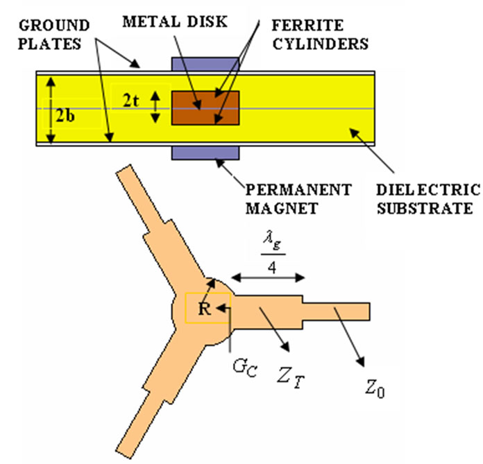
Figure 1. Ferrite film circulator configuration.
 . It is worth mentioning that choosing the quarter wave length transformer is just for simplicity and other matching circuits can be used as well. The permittivities of the dielectric substrate and ferrite cylinders are
  and
and  respectively.
The ferrite is just saturated along  direction, normal to the plane of the device, which means the magnetic flux density produced by the permanent magnet equals to saturation magnetization of the ferrite,
 . In this case the permeability tensor is [20]
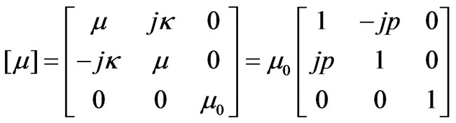 (1)
(1)
where  is the normalized magnetization frequency or splitting factor defined as
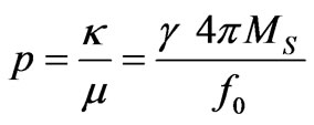 (2)
(2)
In Equation (2), 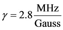 is gyromagnetic ratio,
  is the saturation magnetization in Gauss and
  is the operating frequency.
Resonant modes for which the peripheral of the metal disk becomes PMC or H-wall are very important in ferrite junction circulators design [9]. As we mentioned in introduction, when the splitting factor,  , goes to zero, the resonant frequencies,
  and
and , corresponding to clockwise and counterclockwise modes, which are proportional to
  and
and  respectively, will be degenerated (i.e.
 ). As splitting factor increases the difference between
  and
and  goes up. Also we discussed in introduction about why dipolar modes, which are proportional to
  and
and , are more interesting. To put the circulator in dipolar regime, in which the dominant modes are dipolar modes, we must choose the operational frequency,
  , near the dipolar resonant frequencies,
  and
and . The conventional choice for operational frequency satisfying this condition for operating the circulator in dipolar regime, is
 (3)
(3)
The equivalent circuit of the ferrite junction circulator from the input port when it operates in dipolar regime is shown in Figure 2 [10]. In this circuit the other two ports assumed to be connected to the matched load. As shown in Figure 2 this circuit is the series connection of two shunt R-L-C resonators having resonant frequencies  and
and . The quality factors of the resonators are
  and
and . Indeed all other non-dipolar resonators are effectively short circuited when the circulator operates in dipolar regime. At the operating frequency which is between the dipolar resonant frequencies, according to Equation (3), one of the shunt resonators has a capacitive property and the other resonator has an inductive property and these capacitive and inductive properties cancel each other. In this situation the input admittance of the equivalent circuit is pure real and equals to
  which is the key parameter. Without
  we can not design a matching network systematically.
In practical cases in which the splitting factor is not so large,  [10], detailed analysis of the equivalent circuit shows that the quality factors of each circulator resonators are approximately the same,
  , and we can denote them by a unit symbol
  that is
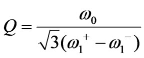 (4)
(4)
Equation (4) shows that the quality factor of the circulator is known, providing we find dipolar resonant frequencies. Finding  and
and  needs to analyze the resonator depicted in Figure 3 [14]. The top of this resonator is the metal disk in the circulator structure; the bottom of this resonator is the ground of the stripline structure. Indeed the elevated stripline ferrite film circulator has one such resonator in each side of the central metal disk. The peripheral wall of the resonator is PMC to find dipolar resonant frequencies.
Full analytical computation of  and
and  is a thorny procedure. In this problem because the splitting factor is small, we can take it as a perturbation and find the electromagnetic fields profile for unperturbed resonator in which ferrite becomes a dielectric. Having the electromagnetic fields for unperturbed structure dipolar
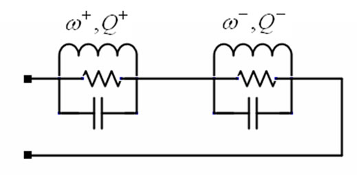
Figure 2. Equivalent circuit looking in the input port of a matched Y-circulator.
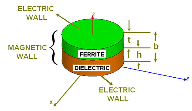
Figure 3. Ferrite loaded resonator.
resonant frequencies for perturbed resonator can be found by computing perturbation integrals. We do these procedures in sections III and IV.
3. Electromagnetic Field Computations for the Unperturbed Structure
For the unperturbed resonator depicted in Fig. 3 in which  goes to zero, using (1), the ferrite becomes a homogeneous dielectric with dielectric constant
 . Consequently we can fiend
  electromagnetic fields for this unperturbed resonator with mixed dielectrics.
For a homogeneous source free region having permittivity  and permeability
 , if
, if  is a wave function in cylindrical coordinates
 then it satisfies the scalar Helmholtz equation
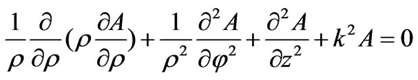 (5)
(5)
where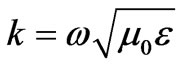 . The components of
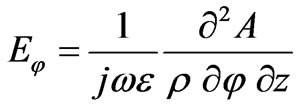
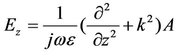
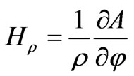
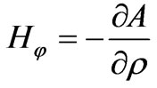
  electromagnetic fields are [21]
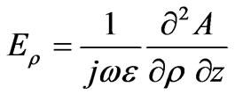 (6)
(6)
 (7)
(7)
 (8)
(8)
 (9)
(9)
 (10)
(10)
 (11)
(11)
For the unperturbed resonator the suitable wave functions which satisfy the boundary conditions on E-walls,  at
at  and
and  (see Figure 3), are
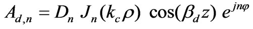 (12)
(12)
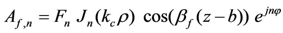 (13)
(13)
where  is the Bessel function of the first kind,
  and
and  is the cut off wave number defined as
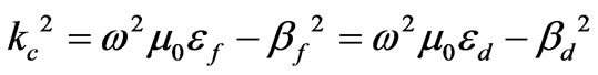 (14)
(14)
The subscripts  and
and , also superscripts hereinafter, refer to the regions
 , dielectric, and
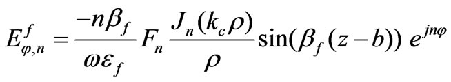
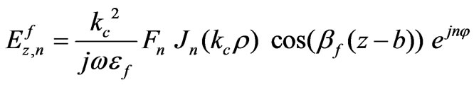
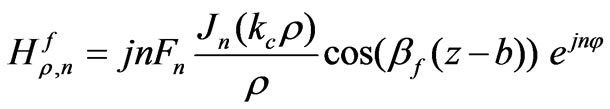
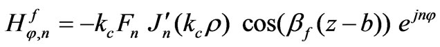
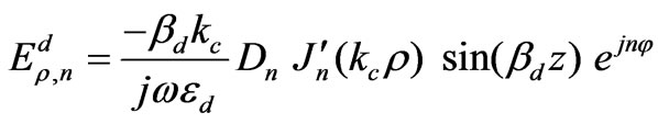
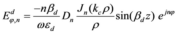
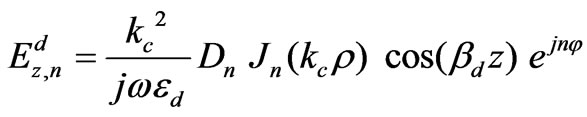
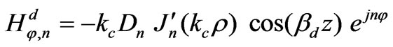
 , ferrite, as shown in Figure 3 respectively. The electromagnetic fields components are obtained from equations (6)-(11)
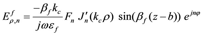 (15)
(15)
 (16)
(16)
 (17)
(17)
 (18)
(18)
 (19)
(19)
 (20)
(20)
 (21)
(21)
 (22)
(22)
 (23)
(23)
 (24)
(24)
 (25)
(25)
 (26)
(26)
Equations (15)-(26) gives the electromagnetic fields profile for unperturbed resonator. For the circulator operating in dipolar regime, only the dipolar modes,  , are important. Indeed we deal with
  mode of the unperturbed resonator. Since the resonant length,
  , for the
  mode is less than
 , (where
  and
and  are the guide wavelengths of the
  dielectric waveguide modes when the permittivities are
  and
and , respectively) the symbol
  is used to denote the
  variation of the resonant mode [22].
Matching tangential components of  and
and  at
at  yields
 (27)
(27)
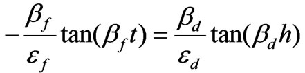 (28)
(28)
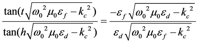
Where , as shown in Figure 3. Equation (28) is a transcendental characteristic equation for the unperturbed structure. The splitting of dipolar resonant modes does not occur because the perturbation, splitting factor, is zero. So the dipolar clockwise and counterclockwise modes for the unperturbed structure have a degenerated resonant frequency which is denoted by
 . When we include the perturbation the splitting between the dipolar resonant frequencies,
  and
and  will occur and so
  or
or . On the other hand if the operational frequency of the circulator is between the dipolar resonant frequencies, the circulator works in dipolar regime so we can take the unperturbed resonant frequency,
  , as our operational frequency,
 .
.
In our design procedure, the resonant frequency of the unperturbed structure,  , is a known parameter and using electromagnetic fields profile for degenerated dipolar modes we can find the radius of the circulator,
 . To do this, satisfying boundary condition of zero tangential
  at
at , magnetic wall, for
  or
or  yields (see Equations (19) and (25))
 (29)
(29)
Where  is the first positive root for the derivative of the Bessel function of the first order and of the first kind,
 . To find
  we should solve the transcendental characteristic equation (28) by substituting
  and
and  from Equation (14). Then we have a transcendental Equation in terms of
 (30)
(30)
To have a suitable range for  in Equation (30) we must note that the resonant frequency,
  , for the unperturbed structure with mixed dielectrics goes to the resonant frequency of the
  mode,
mode,  , when the cavity is completely filled by dielectric
  (where
  ). In an analogous manner
  goes to the resonant frequency of the
  mode,
mode,  , when the cavity is completely filled by dielectric
 . Assuming
 , which is a practical case, we have
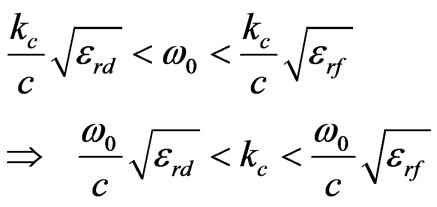 (31)
(31)
Inequality given in (31) presents a good range for finding . Finding
  from transcendental characteristic Equation (30) the radius of the circulator,
  , by Equation (29) readily is obtained.
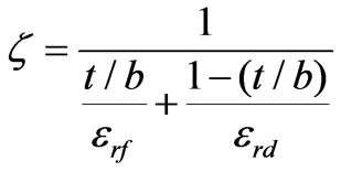
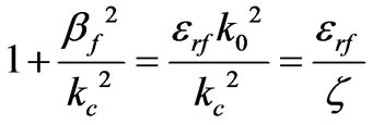
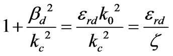
For simplicity we define the symbol  called effective permittivity by
 (32)
(32)
Then from (31) we have . From (14) we can write
 (33)
(33)
 (34)
(34)
Then  is pure real and
  is pure imaginary. In this situation we can write transcendental equation (30) as follows
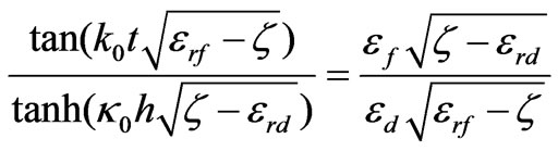 (35)
(35)
In practical cases in which the distance between ground plates is rather small, i.e. , we can replace
  and
and  functions by their arguments. In this situation transcendental Equation (35) takes an algebraic form and effective permittivity,
  , becomes
 (36)
(36)
In Figure 4, for ,
,  (
( ),
), ,
,  , one can plot
  versus
 , the ratio of ferrite thickness by the total thickness of ferrite-dielectric layers. We provide this plot using both transcendental Equation (35) and algebraic one (36). It is evident that as ferrite thickness goes down,
  approaches to
  and in a similar manner as ferrite thickness goes up,
  approaches to
 . This figure can be applied for finding the radius of the circulator. For example if the ferrite and dielectric layers have the same thickness (i.e.
 ) according to Figure 4,
  then
then  or
or  (
( ).
).
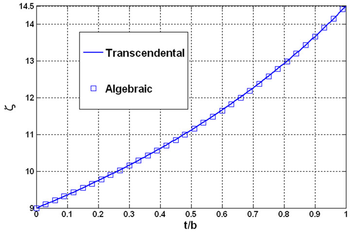
Figure 4. Effective permittivity versus t/b for ,
,  ,
,  and
and .
.
4. Dipolar Resonant Frequencies and Quality Factor of the Perturbed Structure
The resonant frequency for the unperturbed structure analyzed in the previous section is . For the perturbed structure, with non zero splitting factor,
  , by perturbation method described in [23], one can find the frequency separation for dipolar frequencies as follows
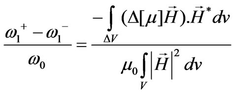 (37)
(37)
where
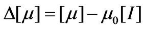 (38)
(38)
and  is the identity matrix.
  is the
  magnetic field for unperturbed structure which we computed its components in (18)-(20) and (24)-(26) for
 . In our especial case,
  is the volume of the ferrite cylinder and
  is the total volume of the resonator depicted in Figure 3. We begin with the expression
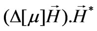
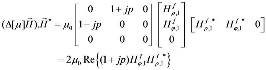 (39)
(39)
Substituting  and
and , Equations (18) and (19) for n=1, in Equation (39) leads
 (40)
(40)
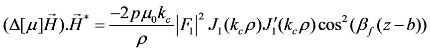
Then the integral of the numerator of Equation (37) can be calculated as below
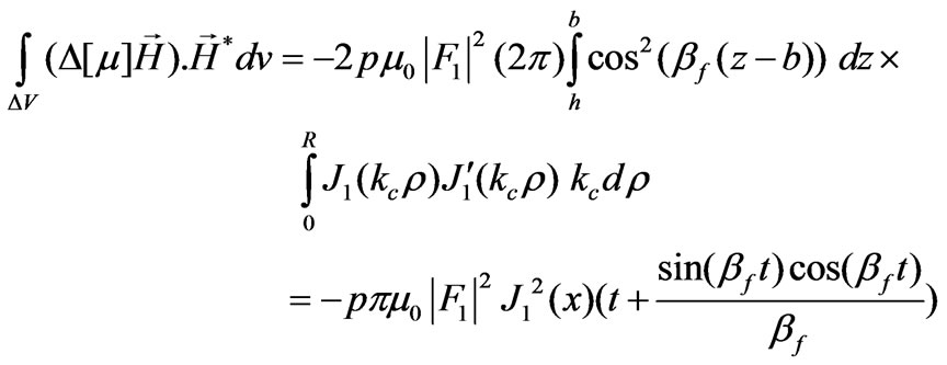 (41)
(41)
Also in  we have
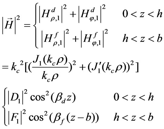 (42)
(42)
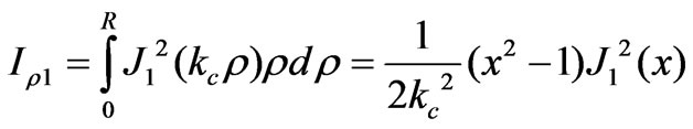
Using the notation given in the appendix we can write the integral in the denominator of the Equation (37) in this form
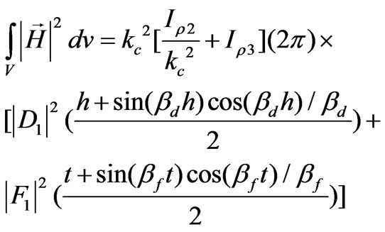 (43)
(43)
Employing (A-1) and (A-4) to compute the radial integral  also by using (27) to relate
  and
and  equation (43) takes this form
 (44)
(44)
Now we have computed the integrals in Equation (37). By substituting the computed integrals, Equations (41) and (44), in (37) we have
 (45)
(45)
Then the quality factor of the circulator is derived using (45) and (4)
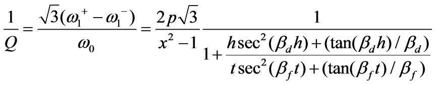 (46)
(46)
In the practical cases in which  we can easily substitute
  functions by unity and
  functions by their arguments so the transcendental complexity in equation (46) can be removed
 (47)
(47)
5. Input Conductance of the Ferrite Film Circulator Using Energy Integrals
The electromagnetic field components computed in equations (15)-(26) are proportional to . For operating the three port as a circulator in dipolar regime (
 ), the circulation condition must be satisfied as follows [10]
 (48)
(48)
where
 (49 )
(49 )
From equations (48)-(49) and (17), the amplitudes of dipolar modes,  and
and  are found:
 (50)
(50)
 (51)
(51)
Having  and
and  the sinusoidal standing wave form of
  is appeared from (49)
 (52)
(52)
where
 (53)
(53)
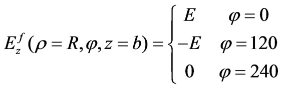
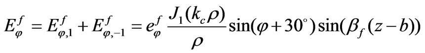
According to (52) dipolar modes create a standing wave pattern proportional to  for electric field on the peripheral of the ferrite cylinders in which
 ,
, and
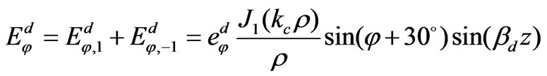
and  correspond to the positions of the input port, output port and isolated port of the circulator respectively. This standing wave pattern makes the polarity of the electric field positive in the half of the peripheral of ferrite cylinders and negative in another half. So the mentioned standing wave pattern make the peripheral of the ferrite cylinders as a dipole and this is the origin of the so-called dipolar modes. Other components of electrical field in ferrite and dielectric layer can be found using the amplitudes of dipolar modes (50)-(51)
 (54)
(54)
 (55)
(55)
 (56)
(56)
 (57)
(57)
 (58)
(58)
where
 (59)
(59)
 (60)
(60)
 (61)
(61)
To find the input conductance of the circulator at the operating frequency we present an electromagnetic computation in this section. This method is based upon the electromagnetic approach for the quality factor of the circulator that is
 (62)
(62)
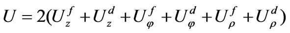
where  is two times as much as the stored energy in the resonator described in Figure 3 (because the stripline structure has one such resonator on each side of the metal disc ), and
  is the power delivered to the output port. We can relate
  to the input conductance of the circulator. Computation of
  is a complicated work for the elevated substrate ferrite film circulators because it deals with energy computations in both ferrite and dielectric layers and all components of electric field vector are present, unlike the conventional ferrite circulators in which only
  component of electric field is non-zero. In the previous section we found the quality factor, equation (46). Then from the relation between
  and
and  we obtain to a closed formula for the input conductance of the circulator.
 is defined as
 (63)
(63)
where  is the outcoming voltage wave at the output port defined as
 (64)
(64)
then using (52) and (58) we reach to a closed form for 
 (65)
(65)
and using (63) we can relate output power to the input conductance
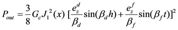 (66)
(66)
Using (53) and (61) we can rewrite Equation (66) as follows
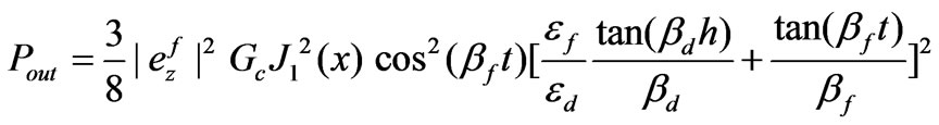 (67)
(67)
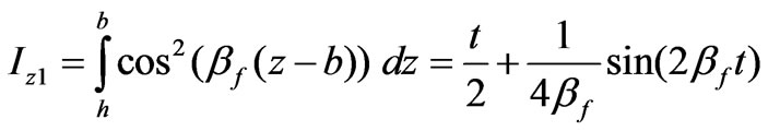
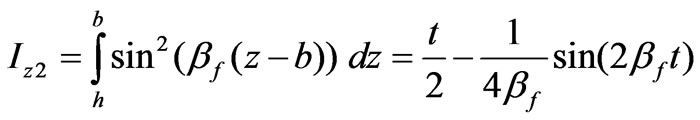
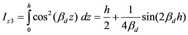
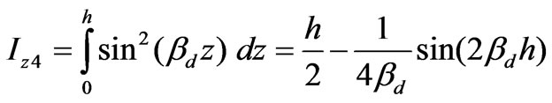
For computing  we can define
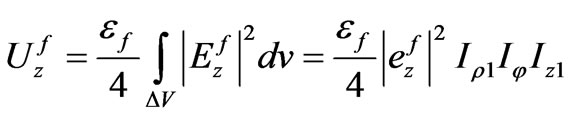 (68)
(68)
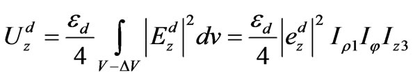 (69)
(69)
 (70)
(70)
 (71)
(71)
 (72)
(72)
 (73)
(73)
where ,
,  and
and  are defined in (A-1)-(A-3) and
 (74)
(74)
 (75)
(75)
 (76)
(76)
 (77)
(77)
 (78)
(78)
 (79)
(79)
By using (59) we can write
 (80)
(80)
The last conclusion of equation (80) was made by (A-4). Using (60), in a manner analogous to equation (80), we can yield
 (81)
(81)
Then by (79)-(81) we can obtain
 (82)
(82)
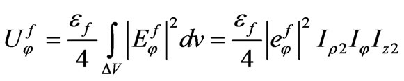
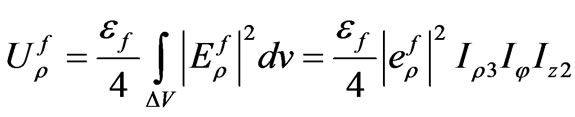
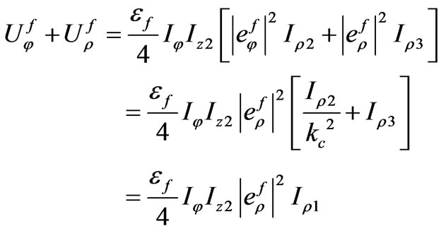
Using (75), (76), (53) and (59) we can expand the first expression in the energy Equation (82)
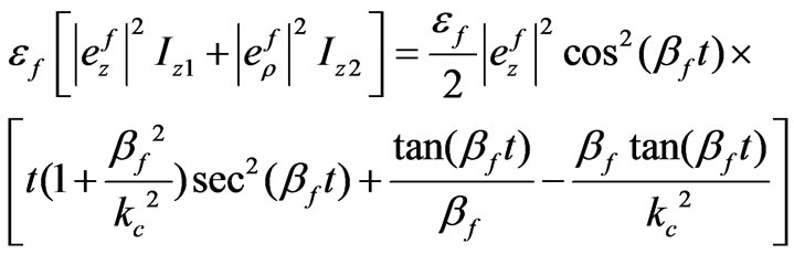 (83)
(83)
Also by (14) and (32) we can write
 (84)
(84)
 (85)
(85)
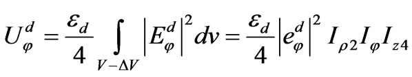
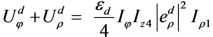
By using (77), (78), (60) and (61) we can expand the second expression in the energy Equation (82)
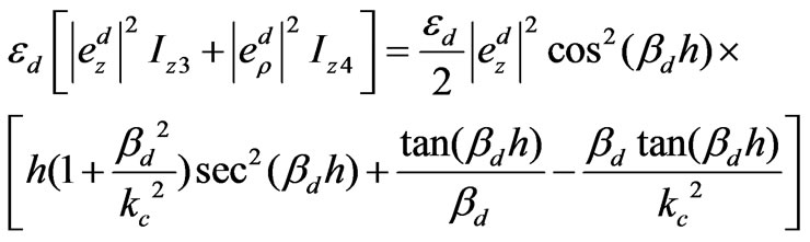 (86)
(86)
By (53), (61), (85) and (86) we have
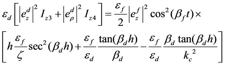 (87)
(87)
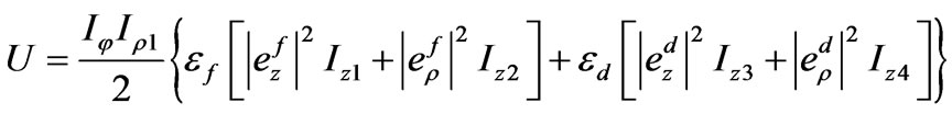
Substituting (83) and (87) in Equation (82) and by us ing (84) we reach (the last terms of (83) and (87) will be cancelled because of characteristic Equation (28))
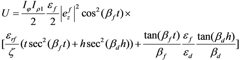 (88)
(88)
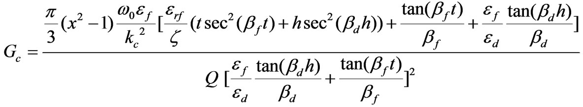
Equation (88) is a closed formula for the energy stored in a cylindrical ferrite-dielectric resonator demonstrated in Figure 3. At this stage we have not only the analytical expression for energy, Equation (88), but also an analytical formula for the power delivered to the output port, equation (67). Then according to (62) the closed formula for the input conductance of the bared circulator is obtained (see Equation (89)).
 (89)
(89)
To reach to the Equation (89) we also used the expressions for  and
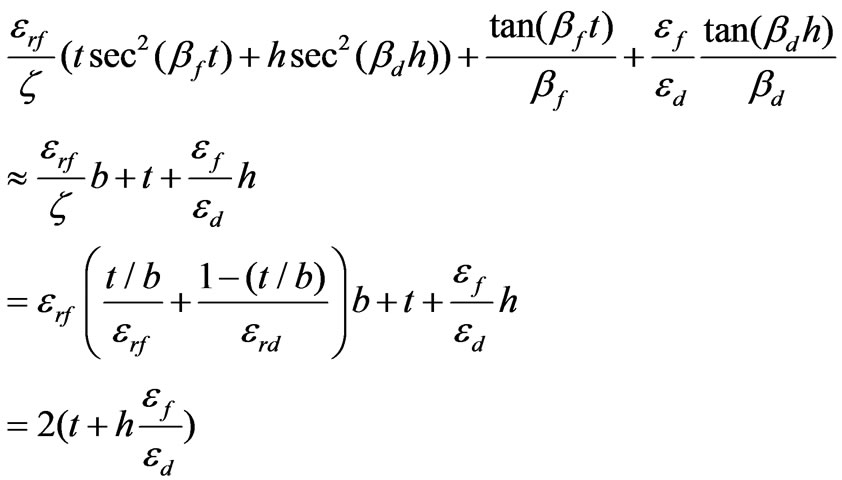
and  given in (74) and (A-1). In the practical cases in which the electrical length,
  , is rather small, we can substitute
  functions by unity and
  functions by their arguments so the transcendental complexity in Equation (89) can be removed as follows
 (90)
(90)
 (91)
(91)
 (92)
(92)
Then using good approximations brought in (90)-(92), the input conductance given in (89) takes very simple form
 (93)
(93)
Equation (93) is the most important result of this paper and very useful to design the suitable matching network for the circulator.
6. Design Procedure for the Ferrite Film Circulator
In this section we summarize a procedure for designing an elevated stripline ferrite film circulator. In this design algorithm we use all the mathematical results in the previous sections.
6.1. Choosing the Operational Frequency and Suitable Ferrite Sample
The splitting factor in practical case must be located in the range . This condition limits our choice of ferrite sample for our desired operational frequency because of Equation (2). Then if we choose a central frequency for operation of circulator, our ferrite sample should have a saturation magnetization so that according to Equation (2), the splitting factor is located in the mentioned interval.
6.2. Choosing the Substrate and the Thickness of Ferrite and Dielectric Layers
In the next section we discuss about the permittivity mismatch for ferrite and dielectric layers. Also the overall thickness of ferrite and dielectric layers must be rather small to be a practical case in MICs. For a rule of thumb  is a suitable choice. In most practical cases the permittivity of ferrite is more than that of the dielectric layer. To have a miniaturized circulator size, it is not appropriate to choose a low permittivity for dielectric substrate.
6.3. Determining the Radius of Ferrite Cylinders
If the electrical thickness of ferrite and dielectric layers is small, the algebraic formula for effective permittivity, Equation (36), can be very useful. Then the radius of ferrite cylinders are found using Equation (29) or equivalently
 (94)
(94)
6.4. Determining the Input Conductance for the Bare Circulator
For the bare circulator (i.e. the circulator without stripline ports) provided the overall thickness of layers is small, we can use simple Equation (93) to find the input conductance of the bare circulator. This input conductance, indeed is the reciprocal value of the reference impedance for which the scattering parameters for the three-port takes the form of the scattering parameters of a good circulator (i.e. with low insertion loss, high isolation and high return loss)
6.5. Determining the Suitable Matching Network
The necessary quarter wave matching transformer impedance,  , as shown in Figure 1 to match the circulator to
  lines is then
 (95)
(95)
To find the width of the striplines, we can use Microwave Softwares. For example MWOFFICE [24] is a useful software.
Table I shows the design parameters for an elevated substrate ferrite junction circulator using the above procedure.
7. Numerical Results
In this section, first we verify the correctness and accuracy of our formula, Equation (93), for the input conductance of the stripline ferrite film circulator using HFSS [19] simulations. By HFSS we can find the scattering
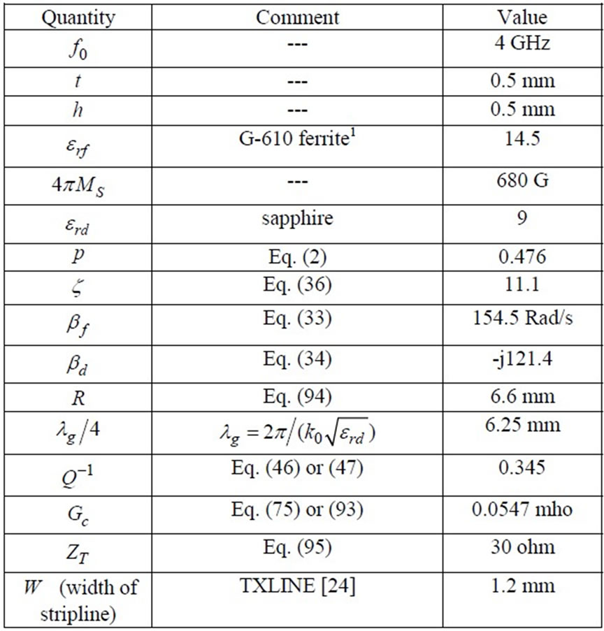
Table 1. Design data for an elevated substrate ferrite film circulator.
parameters of the bare circulator for each reference impedance,  , of the ports. The scattering parameters are the functions of reference impedance. Indeed the input conductance,
  , is the reciprocal value of the reference impedance for which the return loss and isolation are maximum and insertion loss is minimum. We call this suitable reference impedance as
 . By this criterion we can know whether
  is near to
  or not. Return loss, insertion loss and isolation are depicted in Figure 5 versus
  for an elevated substrate ferrite circulator for different permittivites of the dielectric layer. According to these simulations, we can see that
  is very close to
  and their difference is only in few ohms. So Equation (93) is a very good analytical formula for designing the matching network for an elevated ferrite film circulator.
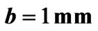
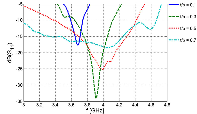
The next thing we can verify numerically is the role of the thickness of ferrite film, effectively shown by,  , on the bandwidth of the scattering parameters. Hartwig and Readey [14] reported that as ferrite thickness is increased, the bandwidth is improved but we lose the integration of our device. So we encounter with a trade-off. In Figure 6 the frequency behavior of the scattering parameters of the ferrite film circulator are demonstrated for some values of
 . This results show that to in-crease the bandwidth of the device, the ferrite thickness should be increased but we should not miss the miniaturization for our purpose. Another problem that is caused by low value of
  is the reduction of the width of the ports. This is a bottle-neck in fabrication because the absolute error in fabricating the striplines with small width is limited.
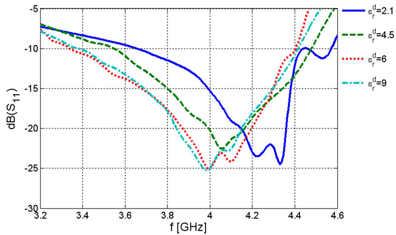
The last numerical result is the effect of dielectric mismatch for ferrite and dielectric layers on the bandwidth of the device. Figure 7 shows the frequency behavior of the scattering parameters of the ferrite film circulator for some dielectrics. Roughly we can say as the permittivity of the dielectric layer increases not only the bandwidth goes up but also we keep the integration of the device.
The concept and formulations developed in this paper allow successful design of the matching network with the use of simple formula for the input conductance for a bared miniaturized elevated ferrite film circulator. Although a simple quarter wavelength transformer is utilized here, our formulation can be applied to other general matching networks to obtain a wider band circulator. Other aspects such as having different ferrite materials for the lower and upper part of the metal disk, can demonstrate desired flexibility to have a wide band circulator. Further designs considering the fabrication realization are in progress.
 (a)
(a)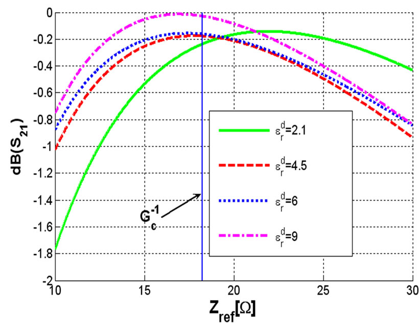 (b)
(b)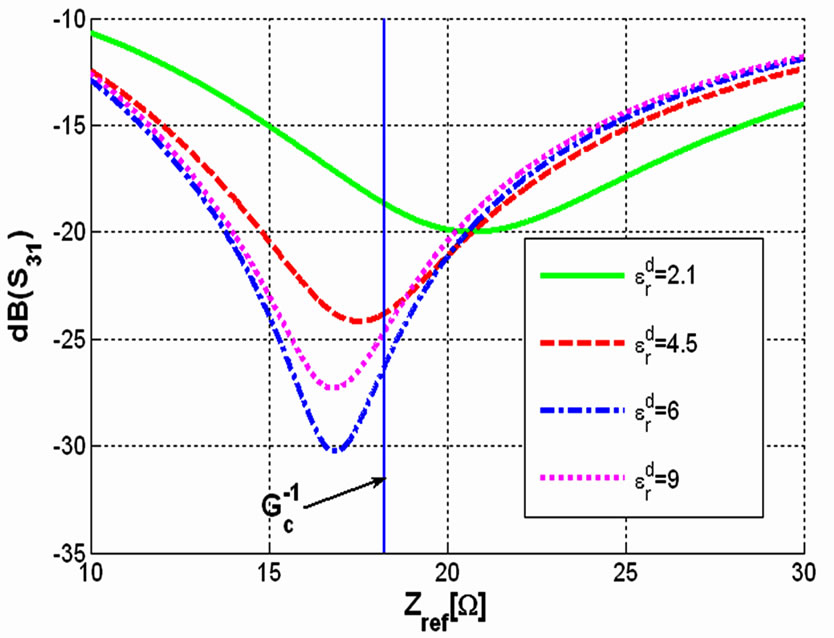 (c)
(c)
Figure 5. Scattering parameters for an elevated ferrite film circulator versus reference impedance for ,
,  ,
, ,
, ,
,  and
and  (a) Return loss; (b) Insertion loss; (c) Isolation.
 (a)
(a)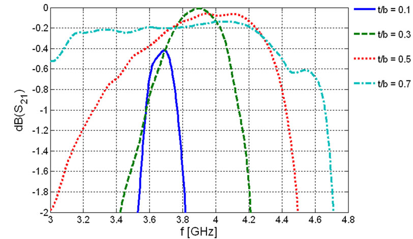 (b)
(b)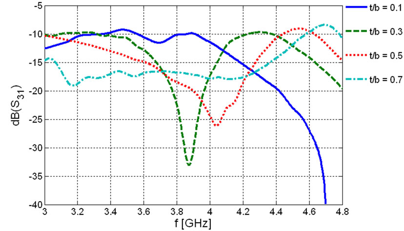 (c)
(c)
Figure 6. Frequency behavior of the scattering parameters for an elevated ferrite film circulator for 
 ,
, ,
, ,
, ,
,
 ,
,  and
and  (a) Return loss (b) Insertion loss (c) Isolation.
 (a)
(a)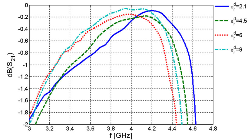 (b)
(b)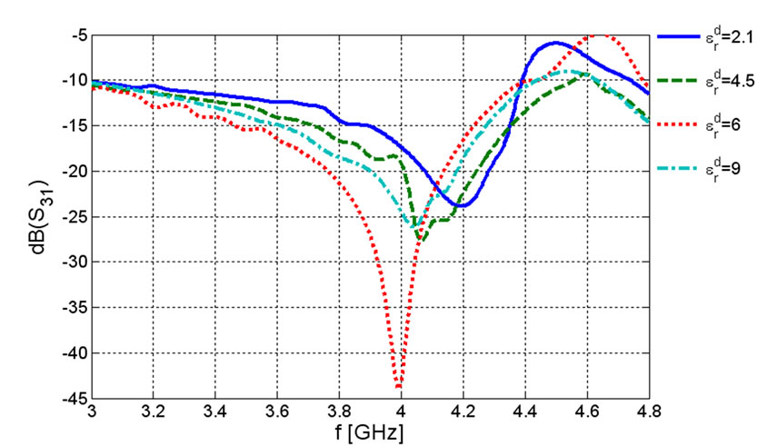 (c)
(c)
Figure 7. Frequency behavior of the scattering parameters for an elevated ferrite film circulator for ,
,  ,
, ,
, ,
, ,
,  and
and  (a) Return loss (b) Insertion loss (c) Isolation.
8. Conclusions
This paper is a complementary to the study of elevated substrate ferrite film circulators. After 40 years of introducing the elevated ferrite film circulator, we answered the question of how we can find the input conductance of the elevated circulator to design a matching network not with trial and error or with approximated formulas which were used 40 years ago. We showed that how a long analytical formulation can end up with a simple formula for the input conductance of the miniaturized ferrite-dielectric circulator. The simple formula depends to the ferrite and dielectric thickness and the splitting factor. We followed circuit approach as well as electromagnetic approach in our design route by successfully employing perturbation method. The procedure to obtain such formula had a lot of mathematical complexity due to perturbation integrals and finding the electromagnetic fields profile in ferrite loaded resonator. The transcendental nature of the result was simplified in the practical case that the electrical thickness of ferrite and dielectric layers is rather small. Finally we verified our analytical result by numerical simulations.
The formulation presented in this paper also can be applied for a multi-layer ferrite structure including more than two layers in each side of the metal disk. The layers can be dielectrics and ferrites with different characteristics. The formulation illustrated in this paper can be applicable not only for stripline but also for microstrip circulators. In microstrip case we need to consider just one ferrite dielectric loaded resonator instead of two resonators. Other matching networks in different configurations can be utilized to match the bare circulator by using the input conductance formula presented in this paper. The proposed technique in this paper enables a capable approach for designing elevated substrate circulators with the use of energy integrals, and perturbation technique presented in this paper.
9. Acknowledgements
The authors would like to thank the help and discussion of Professor Carmine Vittoria in Northeastern University.
REFERENCES
- H. C. Wu and W. B. Dou, “Field Structures of Waveguide Junction Circulators with Irregular Shaped Ferrite Simulated Based on Exact Treatment,” Progress in Electromagnetics Research, Vol. 57, 2006, pp. 33-54.
- J. Helszajn, “Reflection Angles of In-Phase and Split Counter-Rotating Eigenvalues of the Three-Port Circulator,” IEEE Transactions on Microwave Theory and Techniques, Vol. 54, No. 3, March 2006, pp. 1076-1083.
- E. Benevent, T. Rouiller, B. Sauviac, V. Larrey, D. Vincent and A. Madelaine, “Stripline Y-Junction Circulator Using Barium Hexagonal Ferrite Thin Films,” IEEE International Symposium on Industrial Electronics, Vol. 1, No. 1, May 2004, pp. 15-18.
- J. L. Young and J. W. Sterbentz, “The Circular Homogeneous-Ferrite Microwave Circulator—An Asypmtotic Green’s Function and Impedance Analysis,” IEEE Transactions on Microwave Theory and Techniques, Vol. 51, No. 8, August 2003, pp. 1939-1945.
- P. Shi, H. How, X. Zuo, S. A. Oliver, N. E. McGruer and C. Vittoria, “MMW Monolithic Y-Junction Circulator on Single-Crystal Sc-Doped Ba-Hexaferrite,” IEEE MTT-S International Microwave Symposium Digest, Boston, Vol. 2, 2000, pp. 909-912.
- J. D. Adam, L. E. Davis, G. F. Dionne, E. F. Schloemann, and S. N. Stitzer, “Ferrite Devices and Materials,” IEEE Transactions on Microwave Theory and Techniques, Vol. 50, No. 3, March 2002, pp. 721-737.
- R. E. Blight and E. Schloemann, “A Compact Broadband Microstrip Circulator for Phased Array Antenna Modules,” IEEE MTT-S International Microwave Symposium Digest, Albuquerque, Vol. 3, June 1992, pp.1389-1392.
- S. L. Karode and V. F. Fusco, “Feedforward Embedding Circulator Enhancement in Transmit/Receive Applications,” IEEE Microwave and Guided Wave Letters, Vol. 8, No. 1, January 1998, pp. 33-34.
- H. Bosma, “On Strip Line Y-Circuation at UHF,” IEEE Transactions on Microwave Theory and Techniques, Vol. 12, No. 1, January 1964, pp. 61-72.
- C. E. Fay, and R. L. Comstock, “Operation of the Ferrite Junction Circulator,” IEEE Transactions on Microwave Theory and Techniques, Vol. 13, No. 1, January 1965, pp. 15-27.
- H. J. Butterweck, “Der Y Zirkulator,” Arch. Elektron. Uebertragung., Vol. 17, April 1963, pp. 163-176.
- H. How, S.W. McKnight and C. Vittoria, “Effective-Field Theory for Ferrite Thin-Film Junction Circulator,” IEEE MTT-S International Microwave Symposium Digest, Denver, Vol. 2, June 1997, pp. 1127-1130.
- R. R. Jones, R. A. Moore, A. I. Braginski and T. R. Oeffinger, “Elevated Substrate Ferrite Film Circulator,” IEEE GMTT International Microwave Symposium, Arlington Heights, 1972, pp. 241-242.
- C. P. Hartwig and D. W. Readey, “Ferrite Film Circulator,” Journal of Applied Physics, Vol. 41, No. 3, March 1970, pp. 1351-1352.
- L. K. Anderson, “An Analysis of Broadband Circulators with External Tuning Elements,” IEEE Transactions on Microwave Theory and Techniques, Vol. 15, No. 1, January 1967, pp. 42-47.
- K. Oshiro, T. Noborio, H. Fujimori, H. Mikami, S. Fujii, M. Matsuura and S. Yamamoto, “Design of a Circulator with Ferrite Thin Film,” Journal of the Magnetics Society of Japan, Vol. 29, No. 4, 2005, pp. 490-493.
- J. Helszajn, “Experimental Evaluation of Junction Circulators: A Review,” IEE Proceedings on Microwaves, Antennas and Propagation, Vol. 141, No. 5, October 1994, pp. 351-358.
- J. Helszajn, “Scattering Matrices of Junction Circulator with Chebyshev Characteristics,” IEEE Transactions on Microwave Theory and Techniques, Vol. 23, No. 7, July 1975, pp. 548- 554.
- HFSS. ver. 9.1, Ansoft Corporation, Pittsburg, 2003.
- Y. S. Wu, “Wide-Band Operation of Microstrip Circulators,” IEEE Transactions on Microwave Theory and Techniques, Vol. 22, No. 10, October 1974, pp. 849-856.
- R. F. Harrington, “Time Harmonic Electromagnetic Fields,” IEEE Press, USA, 2001.
- D. M. Pozar, “Microwave Engineering,” 3rd Edition, Addison-Wesley, USA, 2005.
- B. Lax and K. J. Button, “Microwave Ferrites and Ferrimagnetics,” McGraw-Hill, New York, 1962.
- AWR Design Environment, ver. 6.51, Applied Wave Research, 2005.
Appendix: Useful Integrals Involving Bessel Functions
 (A-1)
(A-1)
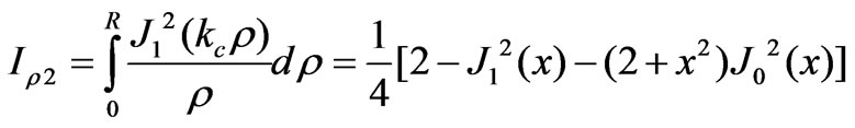 (A-2)
(A-2)
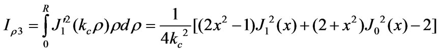 (A-3)
(A-3)
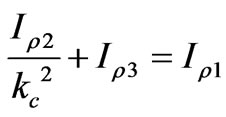 (A-4)
(A-4)
NOTES
We neglect the line-width .
.