Journal of Electromagnetic Analysis and Applications
Vol. 1 No. 3 (2009) , Article ID: 724 , 7 pages DOI:10.4236/jemaa.2009.13023
Delta Modulation with PI Controller—A Comparative Study
School of Electrical & Electronic Engineering, Nanyang Technological University, Nanyang Avenue, Singapore.
Email: Eamaswood@ntu.edu.sg
Received March 7th, 2009; revised May 25th, 2009; accepted June 12th, 2009.
Keywords: Delta Modulation, PI Controller, Voltage Source Inverter, Constant v/f Control
ABSTRACT
The paper discusses the application of PWM delta modulation with PI controller as an alternative to the standard PWM techniques for providing gating signals to the voltage source inverters. Its inherent characteristics of constant volts/Hertz control without feedback complexity and boosting of the fundamental voltage makes it an excellent choice for motor drive applications. This paper discusses the comparison between a basic delta modulation, the advanced Delta modulation with PI controller and an optimized DMPI. It is shown that in addition to the aforementioned advantages, VSI with optimized DMPI produces superior load current/voltage waveforms compared to simple DMPI, when IGBT is employed as a switching device for the inverter. Since the tacho feedback or other traditional speed sensing means is not permissible in sealed motor or the pump, a novel method is used to monitor the motor speed from the terminal quantities like voltage, current, and motor input power factor.
1. Introduction
The fundamental aim of any PWM switching is to eliminate the lower order harmonics at relatively minimal commutation of inverter switches. Attraction of the delta modulation (DM) technique is that it guarantees that the on and off time of the inverter switches will never fall below a given minimum value. DM technique is an established alternative to the traditional sinusoidal PWM switching used in Commercial voltage source inverters driving AC motors. Previous work on DM [1–4] has discussed the objectives, qualities and advantages of delta modulation (DM) technique already from a very specific point of view.
This work gives an overview of the DM from its basic version to the latest state of the art form, i.e. DM with built-in proportional Integral controller.
The adaptive or the rectangular DM has the inherent ability to track the reference signal within a well defined hysteresis threshold level and provides the desired V/f characteristic. The optimal switching frequency and the harmonic control can be easily achieved by:
• Adjusting the integrator R, C parameters.
• Changing the reference signal VR amplitude.
• Controlling the hysteresis threshold level.
• Changing the time constant In the circuit of Figure 1, if the reference Sine wave signal VR is maintained at the same level of modulation, the ratio of the fundamental voltage of the modulated wave to frequency remains constant at all frequencies. This is true for PWM mode of operation. The phenomenon is only valid up to the base frequency, which is the fundamental frequency of the reference wave VR. To investigate these aforementioned important properties of the delta modulator, initially a basic DM circuit in PSIM simulation environment is developed.
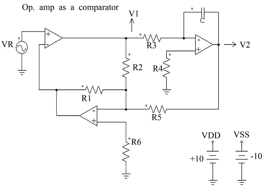
Figure 1. Basic delta modulator
V/f Characteristics
In delta modulation, finding the base frequency i.e. frequency up to which the DM retains constant V/f characteristic, is quite important. Above the base frequency the inverter enters constant voltage region (CVR). The CVR may lead to the saturation of the motor’s magnetic core and is to be avoided [2]. Figure 2(a) shows the V/f relationship of fundamental voltage versus the operating frequency of the input source Vr.
2. Performance Parameters of DM
Various performances of DM are discussed by:
1) Changing the time constants of DM
2) Changing the hysteresis gap of the DM
3) Changing voltage amplitude of the input source Vr.
4) Using PI controller with DM.
2.1 Changing the Time Constant ( )
)
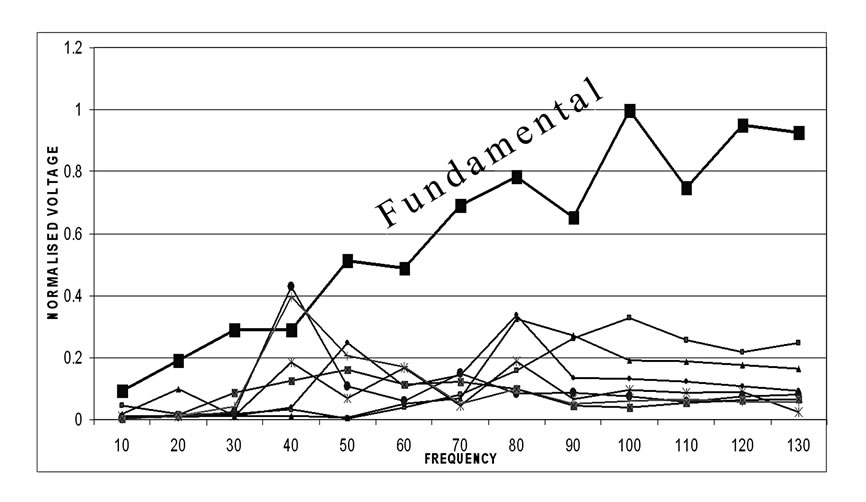
In delta modulation circuit shown above the positive and negative slops of carrier wave V2 depends on the time constant τ =R3C of inverter circuit, using some variations in the time constant by changing R3, different ripple frequency of the carrier waveform can be achieved. Fourier analysis for the harmonic variation of V1 with the changes in time constant τ is carried out for the various values of operating frequencies of the source VR. The results are shown in Figures 2 and 3.
It has been observed, that by making time constant of inverter circuit to τ/3 by changing R3 to 27k, the linearity stage of V/f characteristic is extended to 300Hz. This is three times the standard base frequency which is 100Hz, and the fundamental voltage amplitude is reduced and also there is change in harmonic amplitude of V1.
Using a time constant of 3τ (R3=204k) harmonic amplitude of switching output voltage of DM (V1) is reduced, however the base frequency has been reduced to 50 Hz, this is two times smaller than base frequency(100Hz).
Therefore, it is found from DM operation that, the base frequency is inversely proportional to the inverter time constant τ. A range of R3 value from 27k to 68k is attractive for optimal performance of the DM circuit.
2.2 Changing the Hysteresis Gap of Delta Modulator
The hysteresis gap can be changed by changing feed forward resistor R2 having VR and the τ as constants. Thus by using hysteresis 5 % ,10% and 20 % by changing resistor R2, Fourier analysis for the harmonic variation of V1 was carried out for various frequencies of VR.
V/f characteristic with variation of hysteresis gap from 5% to 20% is shown in Figure 4. The actual harmonic
 (a)
(a)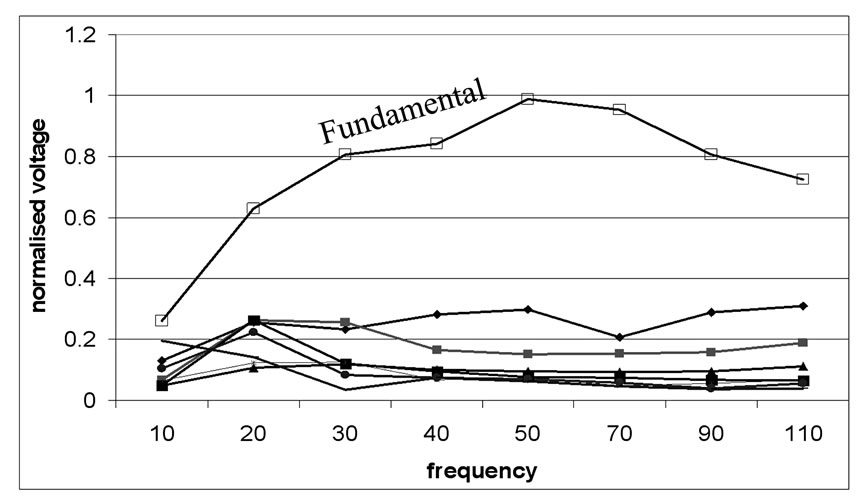 (b)
(b)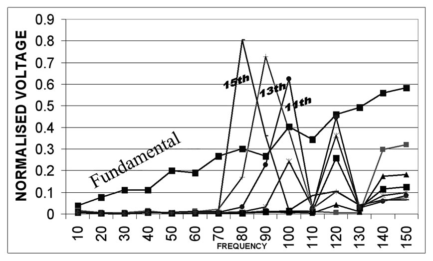 (c)
(c)
Figure 2. (a) Normalized voltage verses frequency distribution with time constant τ, (b) V/f characteristic with time constant 3τ, (c) V/f Characteristic with time constant τ/3
spectrum is not shown as the aim of Delta modulation is to boost the fundamental output voltage (V), which is shown in its normalized form.
It is found from the DM performance that, a lower hysteresis gap provides for a wider base frequency, but the changes in the base frequency are minimal for the various values of hysteresis gap. R2 range of 100k to 200k is optimal for optimum performance of the DM.
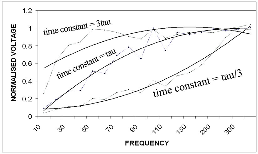
Figure 3. Fundamental component of normalized voltage verses frequency for different time constant
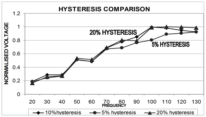
Figure 4. Effect of Constant V/f characteristic with variation of Hysteresis gap, 5%, 10%, and 20%
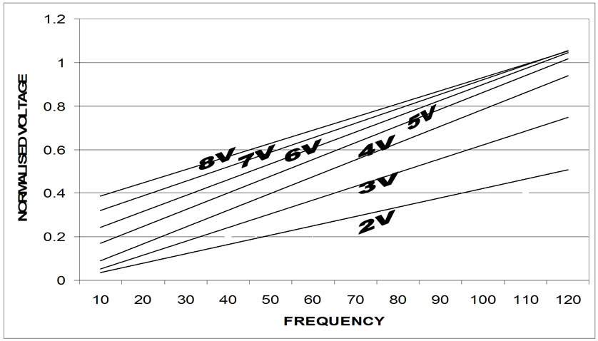
Figure 5. Normalized fundamental voltage vs. frequency characteristics for variation of VR from 2V to 8V
2.3 Changing the Reference Signal Amplitude (VR)
Under this mode the time constant and the hysteresis gap are kept constant. In normal DM operation, VR is held constant. However, if in some applications the base frequency needs to be varied without changing the time constant and the hysteresis gap, it can be achieved by changing VR only. It is found that VR is inversely related to the base-frequency fb. This is shown in Figure 4. A range of 3 to 5 volts for the input source VR is suitable for optimum performance of DM.
3. Properties of DM with PI Control
A PI controller is used to boost up the fundamental voltage of the delta modulator [6,8].The PI controller is inte grated to the delta modulator (DMPI) as shown in Figure 6(a). Fourier analysis was done for three different values of the feedback resister Rf. The respective fundamental output voltages are shown in Figure 6(b).
As observed from the test that, PI controller helps to boost the fundamental voltage widening the gap between the fundamental and harmonic voltages, and it is also observed that the PI introduces a disturbance to the linearity of the V/f characteristics.
The low voltage percentage boost is calculated from the above figures for each value of Rf based on the general DM circuit in Figure 1 & Figure 6(a) means Rf value equals to infinity. It is clear from the above tabulated
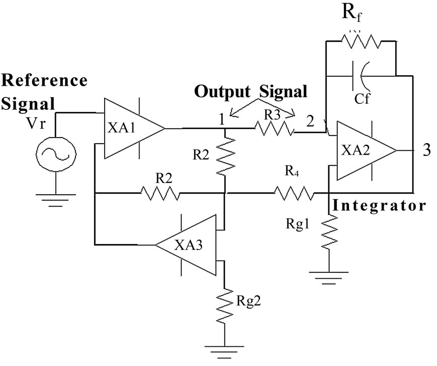
Figure 6(a). Circuit schematic of Delta-modulator with PI controller
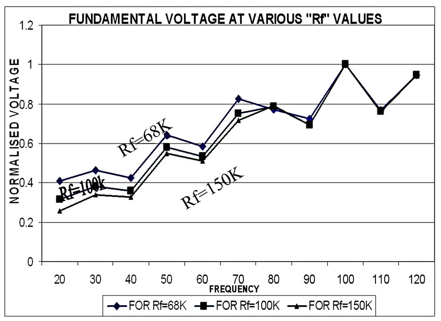
Figure 6(b). A comparison of fundamental normalized voltage for different values of the Rf
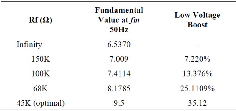
Table 1. Low voltage boosting through Rf
results that with proper selection of Rf, the fundamental voltage amplitude can be boost up to 35.10% as long as the operating frequency is within the base frequency. A range of 45k to 100k is suitable for Rf value for the optimum performance of DMPI.
3.1 Optimized Delta Modulator with PI Control
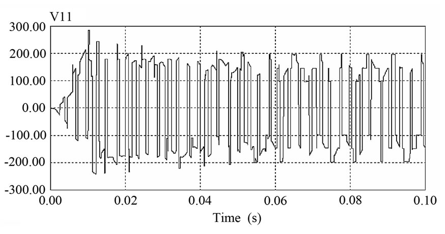
A final and optimum performance based Delta Modulator with PI controller is suggested for inverter (VSI) with the following optimal values: R2=125K, R3=45K, Rf=45k. The harmonic spectrum of switching output voltage of DM (V1) is obtained with suggested optimized DMPI with modulating frequency of 50Hz and 100Hz are shown in Figure 7.
 (a)
(a)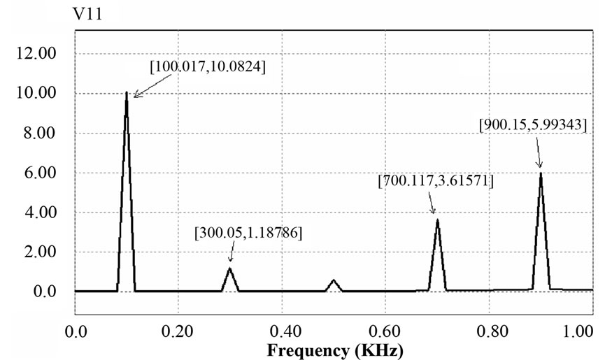 (b)
(b)
Figure 7. Harmonic spectrum of switching output voltage of DM i.e. V1 at modulating frequency (a) 50Hz (b) 100Hz
As one can see in the above figures, the optimized DMPI with modified component values shifts the dominant harmonics towards higher frequencies preferably from the 11th harmonic position. This optimized DMPI model is now used as a driver circuit for the voltage source inverter.
4. Delta Modulator as the Driver
We have selected the above discussed delta modulation (basic DM, DM with PI) techniques for generating the switching gate signal for the IGBT’s of inverter. Analysis of the performance of proposed rectifier-inverter topology [4] carried out for resistive-inductive load.
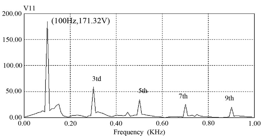
4.1 Performance of Inverter with Basic DM
Rectified DC supply is applied given to an IGBT inverter with the basic delta modulator and it is tested for a RL load(R=18Ohms, L=95mH) at 50Hz and 100Hz operating Frequencies (see in Figures 8 and 9).
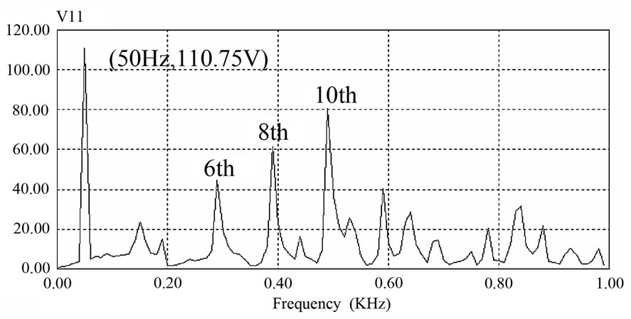
4.2 Performance of Inverter with DMPI
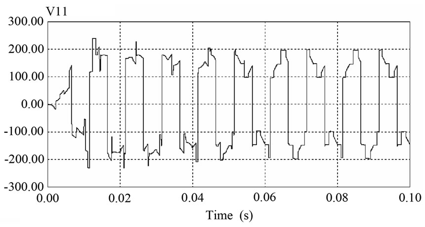
Study is conducted with the delta modulator inverted with PI controller, and it is observed for same resistive inductive load at 50 and 100Hz operating frequencies as shown in Figures 10 and 11.
It can be seen in the Figure 10(b), there is an 11% boost in the amplitude of fundamental component of output phase voltage of inverter for 50 Hz operation of DMPI with respect to basic DM characteristics shown in Figure 8(b).
4.3 Performance Comparison of Inverter with Basic DM and with DMPI
The output phase voltage of the inverters has been studied for both the delta modulation (DM and DMPI) techniques for a range of frequencies with R-L load. The normalized fundamental voltage versus frequency characteristics is plotted and it is shown below. It is seen from the Figure 12, that introduction of PI controller helps to boost up the fundamental voltage compared to that of basic DM. The PI controller also introduces slight disturbance to the V/f characteristic but the linearity is still maintained up to the range of base frequency of 100 Hz.
5. Optimized DMPI with IGBT Inverter
Rectifier-inverter performance is studied with the optimized DMPI, which we have discussed earlier. Optimized DMPI is used to drive the driver circuit for the overall three phase inverters and the output harmonic spectrum generated by the inverter circuit is shown below. It is observed that improved version of DMPI is able to shift the more dominant harmonics to the higher frequencies.
 (a)
(a)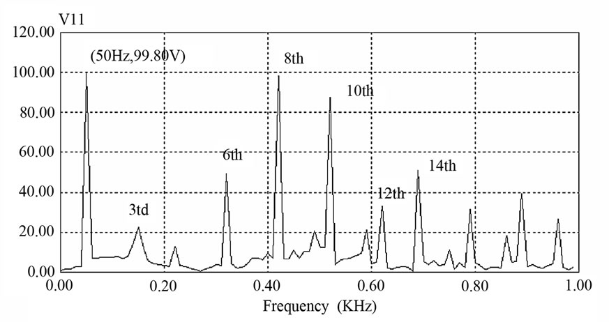 (b)
(b)
Figure 8. (a) Phase voltage waveform with basic DM at 50 Hz. (b) Phase voltage frequency spectrum at 50 Hz
 (a)
(a)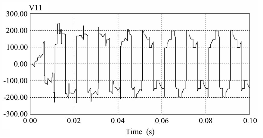 (b)
(b)
Figure 9. (a) Phase voltage waveform with basic DM at 100 Hz. (b) Phase voltage frequency spectrum at 100 Hz
 (a)
(a)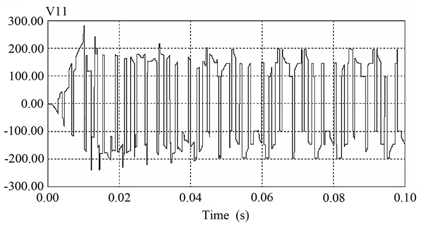 (b)
(b)
Figure 10. (a) Phase voltage waveforms with DM with PI, at 50 Hz. (b) Phase voltage frequency spectrum at 50 Hz
 (a)
(a)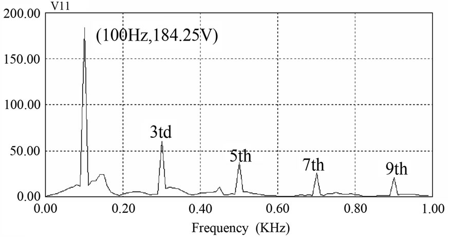 (b)
(b)
Figure 11. (a) Phase voltage waveform with DM with PI, at 100 Hz. (b) Phase voltage frequency spectrum at 100 Hz
5.1 Experimental Results & Drive Application
Figure 14 shows the time domain sample of DM output waveform captured from oscilloscope (Fluke spectrum analyzer). The voltage is normalized with respect to the inverter input dc bus voltage. The spectrum shows the absence of the low frequency harmonics and a high (96.8%) fundamental DM output voltage. Traces of 3rd harmonic still is present due to imperfection in gating signal timing. The output characteristics of the experimental prototype Delta-Modulator is studied at different modulating signal Vr frequency and magnitude levels in order to achieve maximum inverter fundamental output voltage. The results are compared and confirmed with the ones from simulation.
In submersible motor pump application, the DMPI method uses either the voltage or the current variation to maintain the constant slip operation. This is known as the speed variation and is used because the pump production and the efficiency are dependent on the speed of the pump. The operational characteristic of the overall system is shown in Figure 15.
The experimental motor employed is a 1.5 HP squirrel cage submersible induction motor. The motor parameters are given in the Appendix. The variation of inverter voltage, frequency and the resulting motor slip are obtained for a sudden change in load, as shown in Figure 15. When the motor load is increased, the slip increases resulting in a slowdown. The inverter responds by increasing the terminal voltage and frequency. The motor slip eventually decreases and settles to the steady state value after few oscillations. These characteristics also reflect the constant v/f operation of the DM inverter.
6. Conclusions
From the above study of DM techniques, and various comparisons between them, it has been concluded that delta modulation with PI controller helps to provide constant V/F characteristics and boosting of the fundamental voltage especially at low operating frequency. The opti-
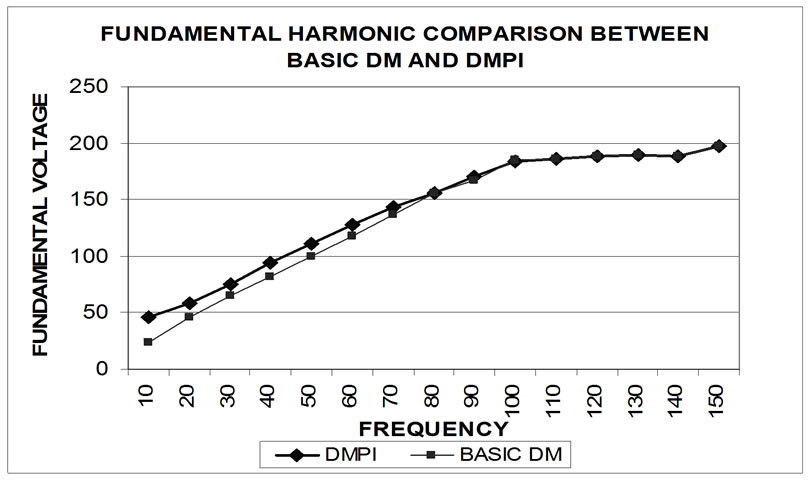
Figure 12. The normalized fundamental voltage versus frequency characteristics
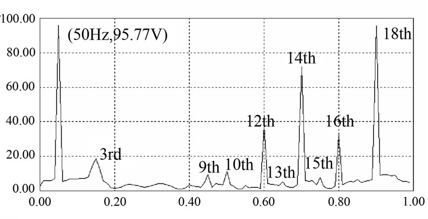
Figure 13. Harmonic spectrum for VSI output voltage using optimized DM with PI
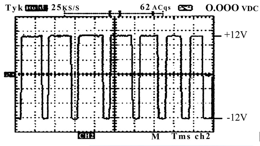
Figure 14. Inverter output waveform from oscilloscope
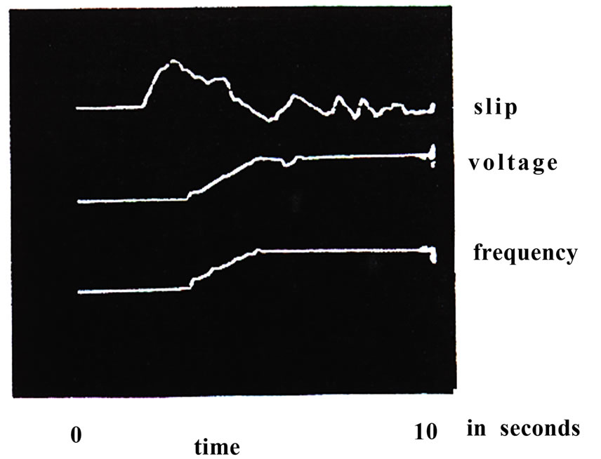
Figure 15. Change of slip, frequency and fundamental voltage for an increase in load at 50Hz operation
mized DM brings about a significant decrease in the harmonic contents towards the 13th harmonic. The DMPI inverter with higher voltage boosting capability and constant V/f characteristic without the feed-back complexity leads to lighter and more economical inverter and the optimized DM inverter with attenuation of low-order harmonics lead to reduced filter size.
It was observed that the motor torque and speed can be instantaneously computed solely from its terminal electrical parameters. It was shown how the DMPI does eliminate the problems existing in SMM. The results of the experimental setup show that the proposed method handles load change overshoots and oscillations with ease, especially where frequency variation with load change is not warranted.
REFERENCES
- P. D. Ziogas, “The delta modulation techniques in static PWM inverters,” IEEE Transactions on Ind. Applications, pp.199–04, Mar/Apr. 1981.
- M. A. Rahman, J. E. Quacioe, and M. A. Chowdhury, “Performance analysis of delta modulated PWM,” IEEE Transactions in Power Electronics, Vol. PE–2, No. 3, pp. 227–233, July 1987.
- T. C. Green, J. C. Salmon and B. W. Willams, “Investigation of delta modulation and of subharmonic elimination techniques,” IEEE PESC Record, Vol. 1, April 1988.
- M. A. Rahman, J. E. Quacioe, and M. A. Chowdhury, “Harmonic minimization in Delta modulated inverters using Tuned filters,” IEEE PESC Record, Vol. 1, April 1988.
- A. I. Maswood, P. D. Ziogas, and G. Joos, “Problems and solutions associated with the operation of phase controlled rectifiers under unbalanced input voltage conditions,” IEEE Transactions on Industry Applications, U.S.A, Vol. 27, No. 4, pp. 765–772, July/August 1991.
- A. I. Maswood and M. A. Rahman, “A survey of delta modulation techniques, characteristics & sub harmonic elimination for VSI,” Electric Machines and Power Systems Journal, U.S.A., Vol. 26, No. 6, pp. 435–448, July 1998.
- A. I. Maswood and S. Wei, “A novel current source PWM drive topology with specific harmonic elimination switching patterns,” IEEE Canadian Conference on Electrical & Computer engineering, CCECE, Halifax, Nova Scotia, May 8–10, 2000.
- A. I. Maswood and M. A. Rahman, ”A PWM voltage source inverter with PI controller, performance parameters under non-ideal conditions,” published in the Electric Power Systems Research [EPSR] Journal, U.S.A, Vol. 38, No. 1, pp 19–24, 1996.
- A. I. Maswood and M. H. Rashid, “A novel method of harmonic assessment generated by 3–Phase AC-DC converters under unbalanced supply conditions,” IEEE Transactions on Industry Applications, U.S.A, Vol. 24, No. 4, pp. 590–597, July/August 1988.
- M. H. Kheraluwala and D. M. Divan, “Delta modulation strategies for resonant link inverters,” IEEE Transactions on Power Electronics, Vol. 5, No. 2, pp. 220–227, April 2000.