Int'l J. of Communications, Network and System Sciences
Vol. 5 No. 5 (2012) , Article ID: 19481 , 10 pages DOI:10.4236/ijcns.2012.55034
Design of Out-of-Band Protocols to Transmit UHDTV Contents in the CATV Network
Department of Information and Communication, Gwangju University, Gwangju, Korea
Email: ssroh@gwangju.ac.kr, ssroh70@gmail.com
Received March 22, 2012; revised April 22, 2012; accepted April 30, 2012
Keywords: UHDTV (Ultra High Definition TV); CATV Networks; Control Protocol; Network Simulation; Protocol Design
ABSTRACT
The goal of an UHDTV is to broadcast digital video contents which is 16 times the pixel resolution of HDTV. As the resolution is increased, the UHDTV requires a transmission technology to support very high data transfer rate. In this paper, we propose two out-of-band protocols to transmit UHDTV contents in a CATV network: an OOB-based protocol and a DSG-based protocol. The former may be a short term solution which is well suitable for a traditional CATV network and the letter may be a long term solution which is adoptable for a CATV network equipped with DOCSIS functionalities. In order to transfer 200 Mbps UHDTV contents, proposed protocols use a channel bonding mechanism which combines several QAM channels. We propose CATV network architectures to support an UHDTV service with a channel bonding mechanism, and design the format of messages to share the information of bonded channels between a headend and a STB. We develop an OPNET simulator and ascertain successful transmission of UHDTV contents.
1. Introduction
The advance of television technologies introduces new services, such as High-Definition TV (HDTV), 3DTV, IPTV, and Smart TV. Furthermore, the requirements of audiences that is to use high-quality TV contents lead to the development of an Ultra High-Definition TV (UHDTV) [1-5]. The UHDTV is a digital video format that has 3840 × 2160 (4 K) or 7680 × 4320 (8 K) pixel resolutions, which are 4 or 16 times larger than 1920 × 1080 (2 K) pixel resolution of the standard full HDTV, respectively. The large pixel resolution of the UHDTV content requires a large screen size and a frame rate. The commercial version of the screen is between about 350 and 600 inches (889 to 1524 centimeters) in size. The frame rate is 30 or up to 60 FPS (Frame per second), more than that of the standard HDTV, 24 FPS. As the pixel resolution, the luminance resolution, and the frame rate are larger, the UHDTV requires a very high data transfer rate. The data rates required for 4 K UHDTV and 8 K UHDTV contents are about 5 Gbps and 20 Gbps, respectively. Although a codec that compresses 100 times is used, the required data rates are 50 Mbps and 200 Mbps.
A digital cable TV (CATV) uses Quadrature Amplitude Modulation (QAM) for broadcast video services. After receiving of video contents from video servers, a headend modulates them through QAM transmission devices. Modulated video contents are transmitted to a broadcast receiving device of a subscriber (e.g., a set-top box) through a transmission channel (QAM channel) predetermined for the video broadcast content stream. The standard in the United States provides both 64-QAM and 256-QAM for a signal transmission over digital cable television systems. This method carries 38.47 Mbps using 256-QAM on a 6 MHz channel. Since 2009, 1024- QAM and 4096-QAM have been proposed and developed in order to increase the transmission efficiency and to transmit a large capacity data [6-8]. The data rate of 1024-QAM and 4096-QAM are about 50 Mbps and 80 Mbps, respectively.
A current digital CATV system assigns one QAM channel for an individual video content stream. As the data rate of UHDTV contents is about 200 Mbps as described above, one QAM channel is not sufficient to transfer UHDTV contents. When a 1024-QAM is used, a 4 K single program transmission stream (SPTS) may be transmitted through a single transmission channel, whereas 4 K multiple program transmission stream (MPTS) may not be transmitted. Furthermore, 8 K video broadcast contents may not be provided through a single QAM channel although 1024-QAM or 4096-QAM is used. In order to provide peak data rates in excess of 50 or 80 Mbps to customers, UHDTV contents are dynamically distributed over a set of transmission channels for delivery to a single user. For example, to transfer an 8 K UHDTV video content, four 1024-QAM channels or three 4096-QAM channels are required.
The focus of this paper is on transmitting 8 K UHDTV contents through a set of QAM channels. For the purpose of this paper, we apply a channel bonding mechanism to transporting UHDTV contents in the CATV network. Channel bonding introduced by the Data over Cable Interface Specification (DOCSIS) 3.0 standard [9] is a principle that combines multiple channels to carry one data stream, and refers to the ability to schedule packets for a single service flow across those multiple channels. The aim of channel bonding is to offer significant increases in the peak data rate that can be provided to a single subscriber. However, the channel bonding is suggested for data services in a DOCSIS network, not for video broadcast services in a CATV network. So, the ultimate goal of this paper is to design new protocols to transmit UHDTV contents in the CATV networks by using the channel bonding.
In this paper, we propose two protocols to transmit UHDTV contents in CATV networks: 1) an Out-of-Band (OOB)-based protocol and 2) a DOCSIS Set-Top Gateway (DSG)-based protocol. The current headend system and set-top boxes use the OOB protocol [10-12] or the DSG protocol [13] as a signaling protocol. In order to minimize the overhead of changing protocols used in the current CATV network and provide the simplicity of applying, this paper proposes protocols based on the OOB protocol or the DSG protocol. We design the OOBbased protocol such as a short term solution to be well adoptable to traditional CATV networks because most of traditional CATV networks use the OOB protocol. On the other hand, to use the DSG protocol requires that a headend and a set-top box provide DOCSIS functionalities. We design the DSG-based protocol for a long term solution as current CATV networks are being equipped with DOCSIS functional modules.
We design network architectures and signaling messages to support channel bonding process. A headend and a STB share the signaling information of bonding channels by signaling messages. Also we propose the process of the set-top box. We make a protocol simulator based on the OPNET and analyze the performance of proposed protocols.
The rest of the paper is organized as follows. In Section 2, this paper provides background information on a channel bonding mechanism, the OOB protocol and the DSG protocol. I design network architectures and protocols in Section 3. Section 4 describes to make an OPNET simulator and to analyze the performance of the protocol. In Section 5 this paper makes the conclusion.
2. Related Works
2.1. Channel Bonding Mechanism
The channel bonding mechanism is a logical process that separates one higher-speed data stream into multiple data packets sent though multiple independent channels, and combines data packets received on multiple independent channels into one higher-speed data stream. An example of the deploying of the channel bonding mechanism in order to transfer 200 Mbps UHDTV contents is as shown in Figure 1. By a 1024-QAM device, the data rate of each channel is 50 Mbps. A 200 Mbps stream is transmitted on a set of four 1024-QAM channels.
2.2. OOB Protocol
The OOB protocol is one of the out-of-band signaling protocol which is specified for transmission of a signaling information in the cable networks. The primary function of the OOB protocol is to establish and maintain an OOB channel that carries signaling messages for exchanging of the signaling information. A network using the OOB protocol consists of a control server, a headend, and STBs. The control server (e.g., a video server or a STB control server) generates control information and frames to maintain Conditional Access System (CAS)/Electronic program guide (EPG)/STB systems. A headend makes OOB messages from signaling information received from control servers, modulates them by using QPSK scheme, and sends modulated frames to STBs on OOB channels.
2.3. DSG Protocol
The DSG specification defines an interface and associated protocol that introduces additional requirements on a DOCSIS CMTS and DOCSIS CM to support the configuration and transport of out-of-band messages between a Set-top Controller (or application servers) and STBs. Like the OOB protocol, the DSG uses a dedicated channel for signaling which is separated from the video channels.
A DSG system physically consists of set-top controllers, CMTSs located in distribution hubs or headends, and set-top devices located in the subscriber’s home.
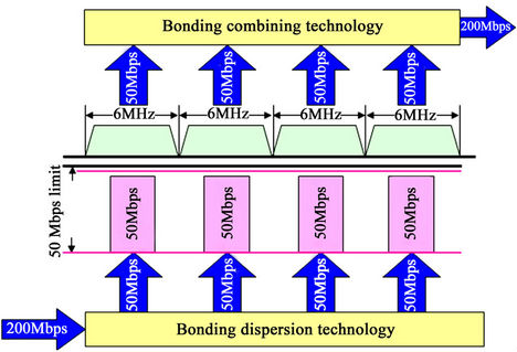
Figure 1. Example of channel bonding.
Figure 2 shows the logical diagram of a DSG system. Out-of-band messages are generated by a DSG server, passed through the DSG agent, and terminated at the DSG client. A DSG channel and a DSG tunnel within a DSG channel are established and maintained for transfer of out-of-band messages between a DSG agent and a DSG client.
3. Design of Out-of-Band Protocols
In this chapter, we design out-of-band protocols to transport UHDTV contents in the CATV networks. As current CATV networks use a legacy OOB protocol or a DSG protocol for out-of-band signaling, we design an OOBbased protocol and a DSG-based protocol. For both protocols, we use the channel bonding mechanism in order to provide the UHDTV contents through several QAM channels.
3.1. OOB-Based Protocol
3.1.1. Network Architecture
The OOB-based CATV network architecture adopted with the channel bonding mechanism is shown in Figure 3. Like a typical OOB network, the network consists of a control server, a headend, and STBs. A headend operating in the OOB-based protocol includes two kinds of processors: one is the signaling processor to serve operations of signaling information, and another is the video processor (VP) to transmit UHDTV contents or other video contents.
The signaling processor performs signaling operations such as establishing an OOB channel, allocating QAM channels for a video content stream, messaging to STBs, and notifying to a video processor. When the headend allocates or changes a set of QAM channels for an UHDTV content stream, the information of bonded channels is notified to STBs via an OOB channel and to a video processor via an internal interface. The operations of the video processor is to receive video contents from video servers, to classify them according to QAM channels preallocated by the signaling processor, to modulate them by a QAM scheme, and to distribute modulated contents for delivery to STBs. On receiving UHDTV contents, the video processor divides them into as much data packets as the number of channels bonded for that UHDTV content stream. Data packets are modulated and sent to a STB via preallocated QAM channels.
The headend may have multiple QAM devices (namely M-QAM), which have one of various modulation/demodulation schemes, for example 64-QAM, 128-QAM, 256-QAM, 1024-QAM, and 4096-QAM modulation/demodulation scheme.

Figure 2. Logical diagram of DSG system.
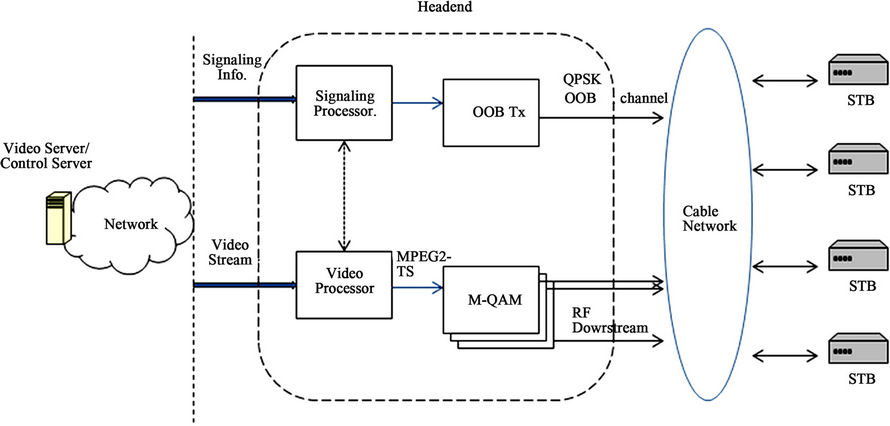
Figure 3. OOB-based cable networ.
Figure 4 shows the functional block diagram of a STB. The STB contains two kinds of functional blocks: 1) video processing block including tuners and demodulators, a channel merger, etc.; and 2) signaling block including an OOB Rx, an OOB QPSK demodulator and a signaling processor.
As four 1024-QAM channels are required for transmission of 200 Mbps 8 K UHDTV content, the STB needs four pair of tuner and QAM demodulator. The channel merger reassembles data packets back into an UHDTV content stream. The OOB Rx receives OOB messages via a OOB channel (or QPSK Forward Data Channel (FDC)) and passes on a OOB QPSK demodulator. Tuning of the OOB Rx is under control of the signaling processor. The signaling processor extracts the information of bonded channels from demodulated OOB messages. If QAM channels for delivery of current UHDTV contents are updated, the control processor resets tuners to changed RF frequencies.
3.1.2. Signaling Message
In order to transmit signaling information, we design new messages, namely channel bonding management messages. Messages are generated by a signaling processor at a headend. As the OOB protocol uses the MAC signaling message format defined by the Digital Audio Visual Council (DAVIC) specification [14], we design signaling messages corresponding to the DAVIC specification. Figure 5 depicts the format of the channel bonding management message.

Figure 4. Function Block Diagram of the STB in the OOB-based cable network.
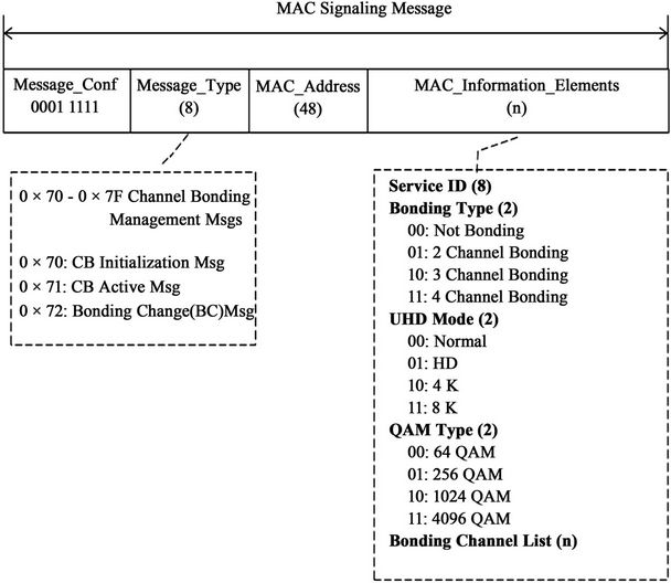
Figure 5. Signaling message of OOB-based protocol.
Each of the signaling messages contains a Message_ Conf field, a Message_Type field, a MAC_Address field, and a MAC_information_Elements field. The Message_ Conf field is 8 bits used to identify current signaling version. The Message_Type field indicates the type of the message being transmitted. For proposed protocol, three message types are defined in this paper: a “Channel Bonding (CB) Initialization Message”, a “CB Active Message”, and a “Bonding Change (BC) Message”. The “CB Initialization Message” indicates that the headend is reactivated or a CATV network is initialized.
The “CB Active Message” notifies that an UHDTV or a video broadcast content is being transported on transmission channels assigned previously. Additionally, the “BC Message” informs that transmission channels or a set of transmission channels for a video broadcast content or a broadcast service are changed.
The MAC_Information_Elements field is divided into five subfields: 1) a (Broadcast) Service ID; 2) a Bonding Type; 3) a UHD Mode; 4) a QAM Type; and 5) a Bonding Channel List. The Service ID subfield uniquely classifies the broadcast service. The Bonding Type subfield indicates the number of bonded channels, from 0 up to 4. The UHD Mode subfield indicates the pixel resolution of broadcast video contents. The QAM Type subfield informs the type of the QAM scheme used by the headend and STBs. In current cable networks, 256-QAM devices are usually used. And 1024-QAM devices are being developing and deploying, and 4096-QAM devices are being researched and implemented. Therefore, channel bonding management messages need to include all kinds of QAM schemes. The Bonding Channel List subfield includes channel IDs allocated for the broadcast service. The length of this subfield may be variable according to the implementation strategy. As we assume that a channel ID has 8 bits and the number of bonded channel is themaximum of 4, the length of the Bonding Channel List is 32 bits.
3.1.3. Message Flow
Figure 6 shows the message flow from a headend to a STB. After finishing the process of ranging and power calibration, a “CB Initialization Message” is sent by the headend to the STB in order to configure transmission channels. If the headend successfully establishes an OOB channel, a “CB Active Message” is sent to the STB. Concurrently, QAM frames are transported by the video processor at the headend
3.2. DSG-Based Protocol
3.2.1. DSG-Based Protocol
Figure 7 shows a DSG-based CATV network architectture. The network consists of a video server or a control server (a DSG server), a headend (a DSG agent), and STBs (DSG clients). The headend includes two kinds of processor: one is a signaling processor for signaling information, and another is a video processor for video content. But unlike the signaling processor in the OOBbased network, the signaling processor in the DSG-based network involves the functionality of CMTS or is the CMTS with operations of DSG.
The signaling processor supports operations as follow:
- Establishing and maintaining a DSG channel and DSG tunnels between a headend and STBs;
- Generating DSG messages and proposed Broadcasting Downstream Channel Description (BDCD) message (described at chapter 3.2.2);
- Allocating QAM channels for an UHDTV content or a video content;
- Notifying the information of bonded channels to the video processor via an internal interface;
- Notifying the information of bonded channels to STBs by using a BDCD message;
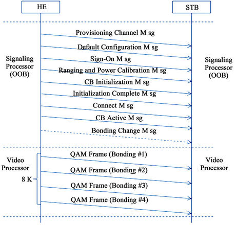
Figure 6. Message flow in OOB-based cable network.
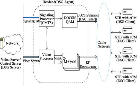
Figure 7. DSG-base cable network.
- Encapsulating and forwarding a BDCD message.
The signaling processor passes a BDCD message on the DOCSIS QAM device, which modulates and delivers them to STBs via a DSG tunnel within a DSG channel. Operations of the video processor include-Receiving video contents from video servers;
- Classifying them according to QAM channels preallocated by the signaling processor;
- Modulating them by a QAM scheme;
- Distributing modulated contents for delivery to STBs.
The functional block diagram of a STB for supporting UHDTV content transport is depicted in figure 8. The STB is equipped with four pairs of tuners and demodulators. The channel merger reassembles data packets back into an UHDTV content stream. The signaling processor at the STB may be a processor supporting not only the functionality of the DOCSIS eCM including DSG functionalities but also the functionality of the channel bonding mechanism. The Tuner-s is tuned to the frequency of the DSG channel, and the demodulator connected to the Tuner-s is a DOCSIS QAM demodulator.
We need to consider two design issues. The first is to support the interactive TV service in a CATV network. The network architecture in Figure 7 and the structure of the STB in Figure 8 support one-way transport without requiring return path functionality from a STB because a CATV network is an one-way distribute network. However, as the requirement of the interactive TV services is increased, the CATV network needs to support two-way transport with a return path from a STB. The second is to provide the OOB interface and the DSG interface together. Recently, a DOCSIS CM including DSG functionality has been embedded into a STB, and both interfaces are provides by the STB. Figure 9 shows the structure of the STB that support the channel bonding mechanism, the two-way transport with the return path, and two interfaces (the OOB interface and the DSG interface).

Figure 8. Function block diagram of the stb in the DSG-based cable network.

Figure 9. Function block diagram of the STB for two-way transport.
3.2.2. BDCD Message
The BDCD message to transfer the signaling information of bonded channels in the DSG-based network is designed according to the format of the DOCSIS MAC Management message, which contains a DOCSIS Message Header, a DOCSIS Management Message Header, and TLV Encoded Information.
The BDCD message contains “Configuration Change Count” field. When the configuration of a network is altered, the value of this field increases. Table 1 summarizes TLVs of the BDCD message, which are used by a headend and STBs to transfer the signaling information. The headend makes a TLV per broadcast service, and then the BDCD message contains the channel information for all broadcast services.
3.2.3. Procedure
Figure 10 depicts the procedure of a BDCD message at a STB. A STB that is turned on or reactivated waits for receiving a SYN message from a headend. On receiving a SYN message, the STB tries to register with the headend. The headend and the STB establish a DSG tunnel within a DSG channel after registering successfully. The headend periodically sends BDCD messages via a DSG tunnel. If the BDCD message is large because the BDCD message contains the information of all downstream channels, the headend splits it up into small data packets and sends fragmented messages to the STB.
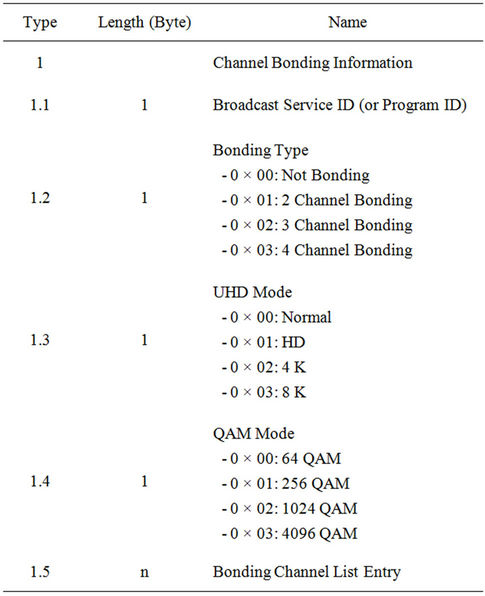
Table 1. TLVs of the BDCD message.
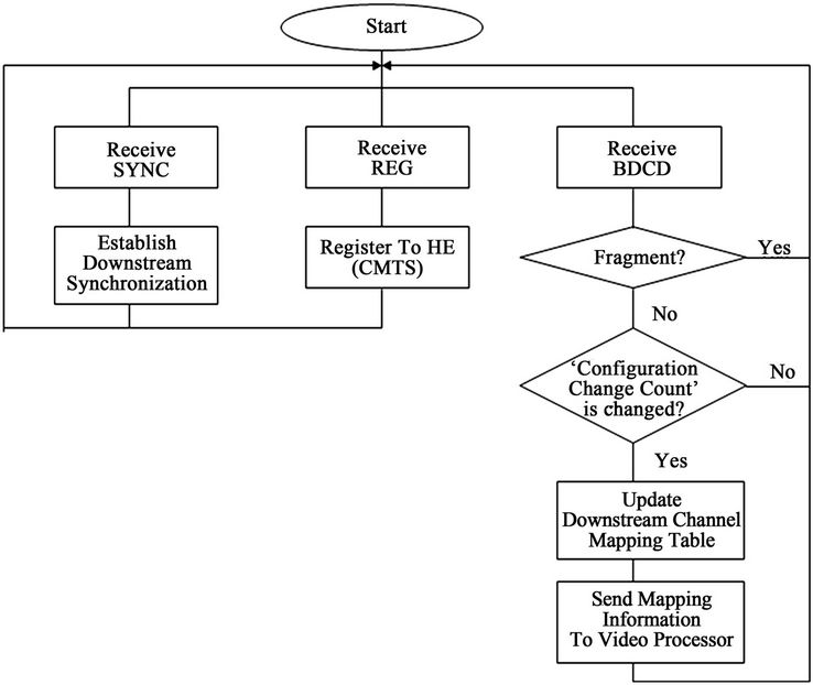
Figure 10. Procedure of the BDCD message at a STB.
Receiving a message, the signaling processor at the STB checks whether the message is a fragmented message or not. If fragmented, the processor stores it at a buffer until receiving all pieces of a BDCD message. If the value of the “Configuration Change Count” within a received BDCD message is different from the current value, the processor updates a downstream channel mapping table. And then the signaling processor resets tuners and notifies changed information to the video processor.
4. Simulation and Results
In order to ascertain the process of the protocol designed in this paper, we make a simulator based on the OPNET [15]. The simulator consists of a network model, node models, process models, packet models and link models. Figure 11 shows the network model. The network includes 3 video servers, one headend, 6 STBs and 6 digital TV (DTV) associated with STBs. The video server generates 4 K UHDTV contents or 8 K UHDTV contents according to the configuration. The video server transmits a MPEG TS stream, which contains UHDTV contents, to the headend via a bidirectional point-to-point link. The headend node has one Tx for the signaling channel and 12 QAM devices for video data channels. The STB node has one Rx for the signaling channel and 4 tuners for video data channels.
The STB sends UHDTV contents to a DTV. We assume that a modulator/demodulator is a 1024-QAM device.
Figure 12 shows the processing results of video servers. We configure two 8 K UHDTV video servers and one 4 K UHDTV video server. As it can be seen in Figure 12, the former servers generate 200 Mbps video streams and the latter server generates a 50 Mbps video stream.

Figure 11. Network model of the simulator.
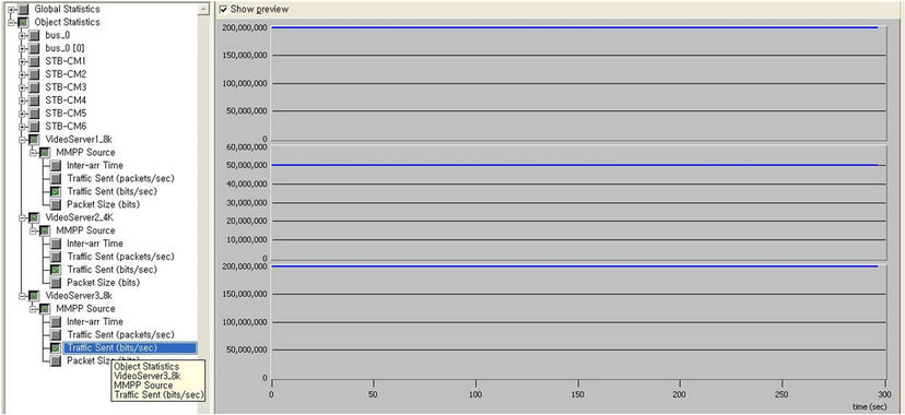
Figure 12. Data rate of contents generated by two 8 K UHDTV video servers and a 4 K UHDTV video server.
Figure 13 shows the data rate received by each tuner at a STB. The STB has registered to use an 8 K UHDTV contents. 4 channels are bonded for 8 K UHDTV transport. We can see that UHDTV contents are transmitted via four bonded channels, not other channels. Figure 14 shows the data rates sent by an 8 K UHDTV video server and received at a STB. Also we know that that 200 Mbps UHDTV contents are normally generated and transmitted 4 bonded channels, and the STB receives segmented packets via four bonded channels, whose data rate is 50 Mbps.
Figure 15 shows the data rates sent by a 4 K UHDTV video server and received at a STB. For 4 K UHDTV content transport, one 1024 QAM channel is used, that is, the channel bonding mechanism is not adopted. It can be seen that 4 K UHDTV contents are normally transmitted from a 4 K UHDTV video server through a head to a STB.
5. Conclusions
The UHDTV is being spotlighted as the primary broadcast service beyond the HDTV. In this paper we firstly applied the channel bonding mechanism into the CATV network, and designed two protocols to transport UHDTV contents in the CATV network: the OOB-based protocol and the DSG-based protocol. As the current CATV system uses the OOB signaling protocol, the OOB-based protocol can be easily adoptable. On the other hand, as the cable network is evolving into IP-based DOCSIS network and the STB has being embedded the functionality of CM, the DSG-based protocol can be used for the
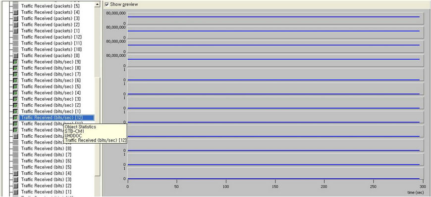
Figure 13. Data rate of contents received via each transmission channel by the STB.

Figure 14. Data rate of contents sent by a 8K UHDTV video server and received by a STB.
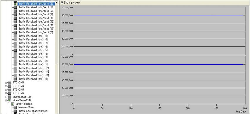
Figure 15. Data rate of contents sent by a 4 K UHDTV video server and received by a STB.
CATV systems supporting the DSG protocol in the near future.
The major trend of the research in the cable network is to support broadcast services (e.g. CATV service, Switched Digital Video (SDV) service, Video On Demand (VOD) service) and narrowcast services (e.g. High speed Internet Service (HSI), VoIP) in the converged cable network.
One of examples is the Converged Cable Access Platform (CCAP). Therefore, we plan to research on the transmission technology for supporting a UHDTV service in the converged cable network.
6. Acknowledgements
The work was supported by the IT R & D program (Development of Next Generation DTV Core Technology) of KEIT & KCC & MKE, Korea and was conducted by research funds from Gwangju University in 2012.
REFERENCES
- F. Okano, M. Kanazawa, K. Mitani, K. Hamasaki, M. Sugawara, M. Seino, A. Mochimaru and K. Doi, “Ultrahigh-Definition Television System with 4000 Scanning Lines,” 2004 NAB BEC Proceedings, 2004, pp. 437-440.
- H. Shimamoto, T. Yamashita, N. Koga, K. Mitani, M. Sugawar, F. Okano, M. Matsuoka, J. Shimura, I. Yamamoto, T. Tsukamoto and S. Yahagi, “Ultrahigh-Definition Color Video Camera with 1.25-Inch Optics and 8 K × 4 K Pixels,” SMPTE Technical Conference and Exhibition, Pasadena, 20-23 October 2004, pp. 1-10.
- S. Sakaida, K. Iguchi, N. Nakajima, Y. Nishida, A. Ichigata, E. Nakasu, M. Kurozumi and S. Gohshi, “The Super HI-VISION CODEC,” Proceeding of ICIP 2007, San Antonio, 16 September 2007, pp. 21-24.
- M. Sugawara, “Super HI-Vision—Research on a Future Ultra-HDTV System,” EBU Technical Report, 2008.
- K. Oyamada, T. Nakatogawa and M. Nakamura, “Ultra-High-Definition Television and Its Optical Transmission,” IEICE Transaction on Communication, Vol. E94-B, No. 4, 2011, pp. 876-883.
- C. Cho, J. Heo and J. Kim, “An Extension of J.83 Annex B Transmission Systems for Ultra-High Definition (UD) TV Broadcasting,” IEEE Transactions on Consumer Electronics , Vol. 55, No. 1, 2011, pp. 63-68. doi:10.1109/TCE.2009.4814415
- C.-P. Fan, W.-H. Liang and W. Lee, “Efficient Fast Blind Equalization with Two-Stage Single/Multilevel Modulus and Dd Algorithm for 64/256/1024QAM Wired Cable Communications,” Journal of the Chinese Institute of Engineers, Vol. 32, No. 1, 2009, pp. 1-15. doi:10.1080/02533839.2009.9671478
- P. Hasse, D. Jaeger and J. Robert, “Boost of Cable Capacity by DVB-C2 Considering Realistic Channel Conditions,” Proceeding of International Conference on Consumer Electronics 2010, Las Vegas, 9-13 January 2010, pp. 19-20.
- CableLabs, “DOCSIS 3.0 MAC and Upper Layer Protocols Interface Specification, CM-SP-MULPIv3.0-I16- 110623,” CableLabs, 2011.
- CableLabs, “Out-of-Band Transfer Interface Specification, OC-SP-OOB-I01-05118,” OpenCable, 2005.
- SCTE, “Digital Broadband Delivery System: Our of Band Transport Part 1: Mode A, ANSI/SCTE 55-1,” SCTE, 2009.
- SCTE, “Digital Broadband Delivery System: Our of Band Transport Part 2: Mode B, ANSI/SCTE 55-2,” SCTE, 2008.
- CableLabs, “DOCSIS Set-top Gateway (DSG) Interface Specification, CM-SP-DSGI15-100611,” Cable Television Laboratories, Inc., 2010.
- Digital Audio Visual Council 1.4 Specification Part 8, “Lower Layer Protocols and Physical Interfaces,” 2012. http://www.davic.org
- www.opnet.com