Int'l J. of Communications, Network and System Sciences
Vol.2 No.6(2009), Article ID:690,6 pages DOI:10.4236/ijcns.2009.26052
Rain Attenuation Impact on Performance of Satellite Ground Stations for Low Earth Orbiting (LEO) Satellites in Europe
Post and Telecommunication of Kosovo (PTK), Dardania, Prishtina, Kosovo
Email: Shkelzen.cakaj@ptkonline.com, shkelzencakaj@yahoo.com
Received May 10, 2009; revised July 2, 2009; accepted August 28, 2009
Keywords: LEO, Satellite, Ground Station, Rain Attenuation, Performance.
ABSTRACT
Low Earth Orbits (LEO) satellites are used for public communication and for scientific purposes. These satellites provide opportunities for investigations for which alternative techniques are either difficult or impossible to apply. Ground stations have to be established in order to communicate with such satellites. Usually these satellites communicate with ground stations at S-band. The communication quality depends on the performance of the satellite ground station, in addition to that of satellite. The performance of the satellite ground stations is expressed through Figure of Merit. The aim of this paper is to analyze the rain attenuation impact on the performance of the respective ground station. Rain attenuation depends on geographical location where the satellite ground station is implemented. In order to compare this effect on satellite ground station performance, some cities of Europe are considered. Finally, the rain attenuation impact on the satellite ground station Figure of Merit for the hypothetical satellite ground station installed in Prishtina is analyzed.
1. Introduction
The typical satellite communication system comprises of a ground segment, space segment and control segment. The function of the ground segment is to receive or transmit the information to the satellite in the most reliable manner while retaining the desired signal quality. The general organization of a satellite ground station consists of antenna subsystem with associated tracking system, transmitting and receiving equipment, monitoring system and power supply as presented in Figure 1. The separation of the transmission and reception is achieved by means of duplexer [1].
The goal of this paper is to analyze the rain attenuation impact on the performance of the ground station (downlink performance) respectively on the received signal quality to the end user as presented in Figure 1.
2. Downlink Performance
For the satellite communication systems the downlink performance (receiving system) is commonly defined through a Receiving System Figure of Merit as , where:
 (1)
(1)
G is receiving antenna gain, TS is receiving system noise temperature, TA is antenna noise temperature and Tcomp is composite noise temperature of the receiving system, including lines and equipment [1]. The satellite ground station receiving system and environment is presented in Figure 2. In Figure 2, TC represents the sky noise temperature, Tm is medium temperature and A is medium attenuation [2]. Undesired noise is in part, injected via antenna (kTAB) and a part is generated internally (kTcompB) by line loss and equipment.
2.1 Antenna Noise Temperature
The antenna temperature depends on where the antenna is looking at. Let us consider the antenna itself is lossless. Under assumption that antenna sees

Figure 1. The satellite ground station architecture.
the sky without medium attenuation, the solid angle subtended by the noise source (sky) is much larger than antenna beam angle (Figure 2), so, antenna noise temperature TA is equal to the sky noise temperature TC. This is the best propagation case, where TA= TC [2]. When an atmospheric absorptive process takes place the absorption increases the temperature. If it is considered the total cosmic temperature as TC, the absorptive medium temperature as Tm and the attenuation due the absorptive process as A, then antenna noise temperature TA is [2]:
 (2)
(2)
TC ranges from 3K to 10K and Tm from 275K to 290K for rain [2]. Rain produces by far the highest attenuation because of the maximal humidity, and represents the worst case in propagation.
2.2. Rain Attenuation
Rain attenuation depends on: number of raindrops along the path, the size of drops and the rain path length [2,3]. Considering the density and the size of drops constant along the distant r, it is found that the power Pr(0) from no raining area will diminish exponentially to the power Pr(r) passing through the raining area with a distance r, expressed as [2]:
 (3)
(3)
where a is the reciprocal of the distance required for the power to drop by a factor e-1 [2]. Expressing this into logarithmic scale as a propagation loss L in [dB] gives:
 (4)
(4)

Figure 2. The ground station and environment.
or, as usually expressed as specific rain attenuation g in decibels per kilometer, it is:
 (5)
(5)
Based on some empirical models it is found out that g (specific rain attenuation) depends only on R, where R is the rainfall rate measured on the ground in millimeters per hour [2]. From these empirical models, the usual form of expressing g is:
 (6)
(6)
where a and b are constants which depend on frequency, polarization and average rain temperature. Table 1 shows values of a and b at various frequencies at 20℃ for both polarization [ITU 838, ITU-R P.838-3].
The reference rainfall rate depends on geographical location. For most of Europe it is 30 mm/h up to 50 mm/h.
Rain attenuation AR (dB) depends on specific rain attenuation g and total rain slant path length lr. Rain attenuation path length geometry is presented in Figure 3 [2]. All heights are considered above mean sea level. The effective rain height hr is the same as the height of the melting layer, where the temperature is 0℃ [2]. Here ε0 stands for elevation angle.
The values for effective rain height vary according to the latitude φ of the ground station [ITU, 618].

Table 1. Parameters of rain attenuation model.
Figure 3. Rain attenuation path geometry.
Since, Europe belongs to the Northern Hemisphere, these values expressed in (km), are given by [2]:
 (7)
(7)
 , for
, for  (8)
(8)
Rain path length from Figure 3 can be expressed as:
 (9)
(9)
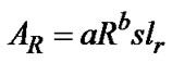
where the hs is altitude of the ground station. Then, rain attenuation AR (dB) for rain path length lr is:
 (10)
(10)
where is .
.
For paths where the angle is ε0 < 5º it is necessary to account for the variation of the rain in the horizontal direction. This effect is treated by implementing a reduction factor s, and then attenuation is given by:
 (11)
(11)
According to [ITU, 618], this reduction factor of rainy path length is empirically defined as [2,4]:
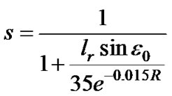 (12)
(12)
e = 2,718 is Nepper constant. This equation is valid for rainfall which does not exceed 0.01% of the time in average year (around 53min) [2].
It is obvious from Figure 3 that the best propagation case is under elevation angle of 90º because of the shortest rain path length. The lock between a satellite and a ground station is established and lost under elevation angles of at least 2º because of natural barriers. This represents longest path and consequently the worst propagation case.
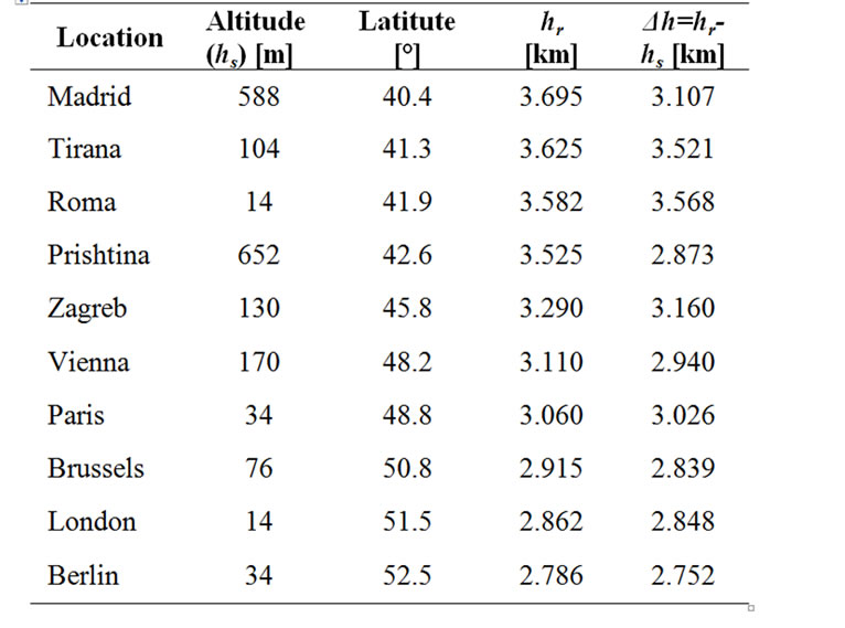
Table 2. Altitude and latitude of European cities.
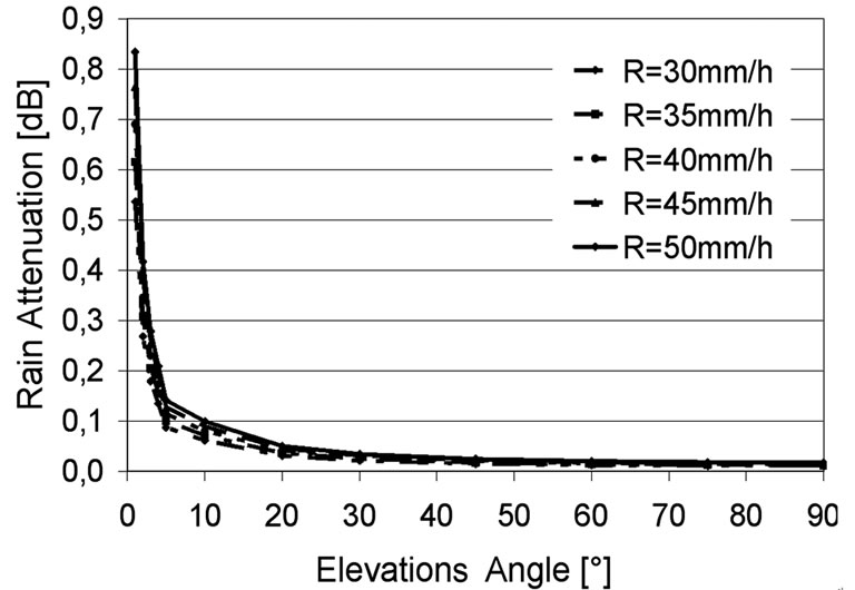
Figure 4. Rain attenuation for different elevation.
3. Rain Attenuation in Europe
Rain attenuation depends on geographical location [4]. Some cities of Europe are chosen where hypothetically is supposed to implement a satellite ground station.
From the http://earth.google.com/ are provided latitude and altitude of these cities as presented in Table 2. Data from Table 2 are used for rain path length calculations [4,5].
The rain path length under elevation angles of 2º is the longest, which accompanied with the highest rain fall rate for Europe of 50 mm/h represents the worst propagation case from the rain attenuation point of view [4,5].
Considering data for Vienna, rain attenuation A [dB] for different elevation angles is presented in Figure 4 [4–6]. For elevation angles below 5º the reduction factor s is applied.
From Figure 4 it is obvious that the rain attenuation

Table 3. Rain attenuation at the worst propagation case.

Table 4. Range of antenna temperature parameters.
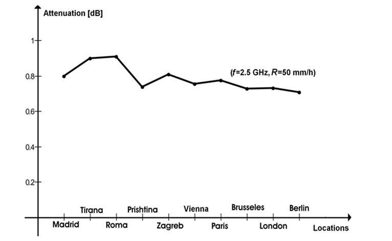
Figure 5. Rain attenuation (f = 2.5 GHz, R=50 mm/h).

Figure 6. Rain attenuation (f =3.5 GHz, R=50mm/h).
is the smallest when antenna is pointed to the sky under an elevation angle of 90º. For an elevation angle of e0 = 2º the rain attenuation is the highest, and represents the worst case for the link budget calculation. Thus the results for the worst propagation case (R=50mm/h and e0 = 2º) based on Equation 6 up to Equation 12 and different frequencies are presented in Table 3.
From Table 3, rain attenuation for frequencies f = 2.5GHz, f = 3.5GHz and R=50mm/h is presented in Figure 5 and Figure 6.
Figure 5 and Figure 6 show that for Central Europe at range of (2–4) GHz the rain attenuation varies from 0.5dB to 3dB. This depends on the operational frequency and location. From Table 3 and Figure 5, it is obvious that the rain attenuation of 1dB, it is sufficient to be considered within a link budget calculations at S-band. Rain attenuation for frequencies less than 2GHz should not be considered.
4. Rain Attenuation Impact on Performance
The downlink performance is expressed through Figure of Merit G/TS. For G/TS calculation, system noise temperature TS must be calculated, respectively, antenna noise temperature TA and composite noise temperature Tcomp (Equation 1). Let us consider firstly antenna temperature from the rain attenuation perspective. Considering Equation 2, for already calculated rain attenuation A and known TC and Tm, easily can be calculated antenna noise temperature TA which directly impacts downlink performance [5]. The range of these parameters is presented in Table 4.
Thus, the antenna temperatures for the worst rain case (e0 = 2º, R=50 mm/h) and the highest Tm=290K and TC=10K are presented in Table 5 and represent the highest possible antenna temperature for respective frequencies related to the listed locations.
The next component at Equation 1 is Tcomp which represents the noise generated by equipment and lines. Since the goal of this paper is to analyze and compare the rain attenuation on the performance of the ground stations, then the system of the same equipment and lines is hypothetically considered to be implemented at the all listed cities. This approach will eliminate equipment impact, leaving room for conclusions only related to the rain attenuation. Considering the Figure 1, in the Table 6 are shown the parameters of the equipment and lines of the hypothetical satellite ground station.
The composite noise temperature Tcomp is calculated based on Equation 13 [7], as:
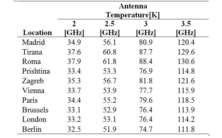
Table 5. Antenna temperature.
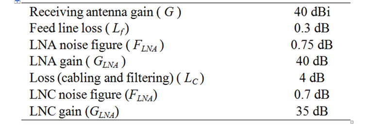
Table 6. Parameters of hypothetical ground station.
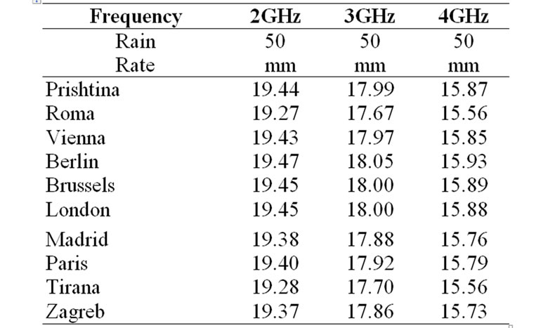
Table 7. Figure of merit [G/TS (dB/K)].

Figure 7. Figure of merit (Prishtina case).
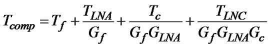 (13)
(13)
Considering, Equation 13 and Table 5 about the highest possible antenna temperature it is calculated Figure of Merit for frequency band (2–4) GHz, for the hypothetical satellite ground station implemented at all listed location and presented in Table 7 [8].
Results of calculations show that for the same frequency and the same rain fall rate the difference in Figure of Merit among cities is less than 0.2dB. This means that the ground station’s performance within central Europe does not strongly depend on location. This fact creates open opportunities for the implementation of the LEO ground stations in Europe for different purposes. For Prishtina city, Figure of Merit on dependence of frequency in Figure 7 is presented.
For the same parameters from Table 7, just by changing the receiving antenna gain the Figure of Merit is calculated and presented. These diagrams confirm that the main improvement on the figure of merit could be achieved by the receiving antenna gain.
5. Conclusions
The rain attenuation analyses are related to link budget considerations due to the ground station design. For Central Europe at range of (2–4) GHz the rain attenuation varies from 0.5dB to 3dB. The performance of the ground station within central Europe does not strongly depend on location. The difference on downlink figure of merit among all considered cities in central Europe for S-band in average is less than 0.2dB under the same rain fall rate, or in average less than 1dB for different rain fall rates. Rain attenuation of 1dB, it is sufficient to be considered within link budget calculations at S-band.
6. References
[1] G. Maral and M. Bousquet, “Satellite communication systems,” John Willey & Sons, Ltd, Chichester, England, 2002.
[2] S. R. Saunders, “Antennas and propagation for wireless communication systems,” John Wiley, Ltd, Toronto, 1993.
[3] P. G. Pino, J. M. Riera, and A. Benarroch, “Slant path attenuation measurements at 50GHz in Spain,” IEEE, Antennas and Wireless Propagation Letter, Vol. 4, pp. 162–164, 2006.
[4] S. Cakaj and K. Malaric, “Rain attenuation at low earth orbiting satellite ground station,” in Proceedings of 48th International Symposium on Multimedia Systems and Applications, ELMAR, Zadar, Croatia, pp. 247–250, June 2006.
[5] S. Cakaj and K. Malaric, “Rain attenuation modeling for low earth orbiting ground station at S-band in Europe,” in Proceedings of IASTED, 18th International Conference on Modeling and Simulation, Montreal, Canada, pp. 17–20, May 30–June 1, 2007.
[6] W. Keim and A. L. Scholtz, “Performance and reliability evaluation of the S-band, at Vienna satellite ground station,” Talk, IASTED, International Conference on Communication System and Networks, Palma de Mallorca, Spain, 5 pages, 2006.
[7] S. Cakaj and K. Malaric, “Rigorous analysis on performance of LEO satellite ground station in urban environment,” International Journal of Satellite Communications and Networking, Vol. 25, No. 6, pp. 619–643, UK, November/December 2007.
[8] S. Cakaj and K. Malaric, “Downlink performance comparison for low earth orbiting satellite ground station at S-band in Europe,” IASTED, in Proceedings of 27th International Conference on Modeling, Identification and Control, Innsbruck, Austria, pp. 11–13, February 2008.