Int'l J. of Communications, Network and System Sciences
Vol.2 No.3(2009), Article ID:468,18 pages DOI:10.4236/ijcns.2009.23021
Fast and Noniterative Scheduling in Input-Queued Switches
Department of Computer Science, University of Texas at Dallas, Richardson, Texas, USA
Email: {kchen, edsha, sizheng}@utdallas.edu
Received April 22, 2009; revised May 22, 2009; accepted May 25, 2009
Keywords: Switch Architecture, Switch Fabric, Fabric Scheduling, SRA
ABSTRACT
Most high-end switches use an input-queued or a combined inputand output-queued architecture. The switch fabrics of these architectures commonly use an iterative scheduling system such as iSLIP. Iterative schedulers are not very scalable and can be slow. We propose a new scheduling algorithm that finds a maximum matching of a modified I/O mapping graph in a single iteration (hence noniterative). Analytically and experimentally, we show that it provides full throughput and incurs very low delay; it is fair and of low complexity; and it outperforms traditional iterative schedulers. We also propose two switch architectures suited for this scheduling scheme and analyze their hardware implementations. The arbiter circuit is simple, implementing only a FIFO queue. Only half as many arbiters for an iterative scheme are needed. The arbiters operate in complete parallel. They work for both architectures and make the hardware implementations simple. The first architecture uses conventional queuing structure and crossbar. The second one uses separate memories for each queue at an input port and a special crossbar. This crossbar is simple and also has a reduced diameter and distributed structure. We also show that the architectures have good scalability and require almost no speedup.
1. Introduction
There has recently been renewed interest in building new switch fabric architectures as line rates go from 10 Gbps to 1 Tbps and beyond. Existing architectures are not very scalable. As memory technology evolves, switching techniques that would otherwise be considered unworkable may now be implemented. New switch fabrics can and should now be fast and highly scalable. In this paper, we propose and analyze two such novel fabric architectures.
By queuing structure, there are input-queued (IQ) switch, output-queued (OQ) switch, and combined inputand output-queued (CIOQ) switch. An OQ switch buffers cells at the output ports. OQ switches guarantee 100% throughput since the outputs never idle as long as there are packets to send. OQ switches are hard to implement. An N × N OQ switch must operate N times faster than the line rate. Memory technology cannot meet that kind of high-speed requirement. Therefore, IQ and CIOQ switches have gained widespread attention and adoption. The most common architecture is the CIOQ switch in which buffering occurs both at the input and at the output. Output queues are for traffic scheduling which provides fine-tuned service support. Both IQ and CIOQ switches use virtual output queuing by which each input maintains a separate queue for cells destined for each output or of a flow of a certain service requirement. Such a queue is called a virtual output queue (VOQ). Virtual output queuing removes head-of-line (HOL) blocking that can severely limit the throughput when only a FIFO queue is used for all the packets at each input.
It is customary to use a crossbar to interconnect the input and output ports due to its simplicity and nonblocking property. A crossbar can either have memory or have no memory at its crosspoints. Our work is for IQ switch architectures using unbuffered crossbars. Crossbar access by the input cells has to be arbitrated by the fabric scheduler. Traffic scheduling manipulates the cells further to meet rate and delay requirements of various services. Fabric and traffic schedulers can be considered as separate identities. They must work in coordination to maximize datapath utilization.
The IQ fabric scheduling problem is key for building efficient switches. Many algorithms have been proposed for scheduling an IQ switch to obtain high throughput. The algorithms all find a matching between the inputs and outputs, but they were derived with different techniques. Under the matching paradigm, the scheduler matches an input with an output and finds the maximal number of those pairs in a time slot. This usually takes a few iterations for one time slot. Numerous algorithms work in this iterative way and are hereof called iterative algorithms. Those pairs are found globally and do not conflict one another. The scheduler uses the information on the states of the input queues and the output readiness to make the matching decision.
The cell scheduling problem for switches is conventionally modeled as bipartite matching over a graph G as follows. In each time slot, G is constructed such that there is an edge from each input port to each output port. The ports are represented as vertices or nodes in G. This implies that at most one cell from a VOQ at an input port can be sent to its destined output port, which corresponds to one edge in G being selected. The bipartite matching over G is the process to find a set of edges such that their vertices do not overlap. A maximal matching contains the largest number of edges possible to be selected in a time slot in the number of iterations set according to an iterative algorithm. A maximum matching selects the maximum number of edges, i.e. every input port is matched to a distinct output port if the input port has a queued cell that is going to a distinct output port.
Our scheduling algorithm, called SRA, is noniterative. Matching is done in a single iteration during a time slot and its efficiency is much higher. SRA runs in O(1) time and always finds a maximum matching, although the matching is done over a graph G' modified after G as to be detailed in Section 4. In G', the VOQs at the input ports along with the output ports form the vertices instead of just the input ports plus the output ports as in G. Matching still aims to find the largest number of edges of G' that do not overlap and is done in a single iteration. The basic idea is to allow each input port to send up to multiple cells each from a different VOQ to a different output port in a time slot. Arbitration is implemented by a single round-robin arbiter for each output port. The SRA algorithm is different from the iterative algorithms in terms of the arbitration process. In SRA, an arbiter, consisting of a FIFO queue, is maintained for each output port. The arbiter selects the input port corresponding to the first queued cell. Hence, the arbitration done in iSLIP and other iterative algorithms is not needed.
For hardware implementation, we propose two architectures to support SRA. Both architectures rely on the arbiter construct which is just a FIFO queue. They differ in queuing structure and the crossbar each uses. The first one uses conventional queuing structure and crossbar. The second uses separate memories for VOQs at each input port and a special crossbar.
In this paper, we show that the SRA algorithm is workable, simple, fast, and scalable. We analyze SRA’s characteristics. Simulation results also demonstrate that SRA is far more efficient than the popular matching algorithms. We show that the SRA architectures are simple, fast, and effective. We also discuss the hardware implementations. The architectures could be used in switches and routers. No other similar architectures have been proposed. We hope our architectures provide viable alternatives for designing nextgeneration switch fabrics.
Note that the second architecture assumes a multiplemultiplexer structure and requires VOQs be buffered in separate memories and connected to the custom crossbar differently from the first architecture. Therefore, throughout the paper, we use the term “input-queued switch” to refer only to the fact that traffic is buffered at the input ports in VOQs in such a switch, regardless of the memory makeup for the VOQs and the crossbar structure.
The rest of the paper is organized as follows. In Section 2, we review related work including the very latest. We discuss the iterative algorithms in detail. Section 3 gives an overview of the SRA fabric, in comparison with a conventional iterative one. Section 4 contains the SRA algorithm and its complexity analysis. Section 5 contains the analytical results of the SRA algorithm. Section 6 contains the simulation results that show SRA’s performance in handling various traffic types, scalability, and cell blocking at input ports. Section 7 shows the hardware aspects of SRA. It covers queuing structure, crossbar, arbiter, and architecture scalability. It also includes a comparison of the architectures to the Knockout Switch. Section 8 concludes the paper, where we highlight the achievements and innovations of this research work.
2. Related Work
The field of IQ switch scheduling boasts of an extensive literature. Many algorithms exist, derived with different techniques. Some of them are of more theoretical import, whereas others are more oriented to implementation. Here we review a representation of the works.
In graph-theoretic terms, the cell scheduling problem for switches can be modeled as a bipartite matching problem as follows. Let Ii and Oj denote input port i and output port j respectively. Let VOQi,j denote the VOQ at Ii holding cells destined for Oj, and VOQi,j(t) the length of VOQi,j at time slot t. In each time slot t, we construct a bipartite graph G(V,E) such that V = V1 ∪ V2, V1 = {Ii|1 ≤ i ≤ N}, V2 = {Oj|1 ≤ j ≤ N}, and E = {(Ii,Oj)|VOQi,j(t) > 0}. Graph G is called an I/O mapping graph. A matching is defined as the set M ⊆ E such that no two edges in M are incident to the same node in V. A maximum matching is one with the maximum number of edges, whereas a maximal matching is one that is not contained in any other matching found in an iteration when a matching is done iteratively in a prefixed number of iterations in a time slot.
Work by McKeown et al. [1,2] shows that a 100% throughput can be achieved by using a longest queue first (LQF) or an oldest cell first (OCF) scheduling policy for independent identically distributed (i.i.d.) Bernoulli traffic with uniform or non-uniform destinations. LQF and OCF are both maximum weight matching algorithms. McKeown et al. proved the result using a linear programming argument and quadratic Lyapunov function. In related work, Mekkittikul and McKeown [3] used the longest port first (LPF) scheduling policy to obtain full throughput. Those scheduling policies appear to be too complex for hardware implementation due to the inherent O (N3logN) complexity of maximum weight matching.
Iterative techniques can be used to find the bipartite matching. Example iterative algorithms include iSLIP [4,5], 2DRR [6], and WRR [7]. These algorithms all use round-robin; the first two are unweighted and the last one is weighted using idling hierarchical round-robin. As discussed in [2], these solutions can get a throughput of more than 90% for uniform traffic but will fare worse when traffic is nonuniform. These algorithms have an O(N2) worst-case time complexity. Although they can converge in O(logN) iterations, they tend to incur long delay and have poor scalability.
Yang and Zheng [8] proposed an iterative scheduler that uses space-division multiplexing expansion and grouped inputs/outputs to realize speedup while switch fabric and memory operate at line rate. They formulated packet scheduling as a maximum bipartite k-matching problem. They proved by a fluid model method that full throughput can be obtained when the expansion factor is 2, with only mild restrictions on traffic arrivals. They also proposed the kFRR scheduling algorithm to implement the multiplexing and grouping for full throughput. Since their scheme is iterative, it is prone to long delay and low scalability.
Chao et al. proposed and studied another matching architecture called dual round-robin matching (DRRM) [9-11]. DRRM is similar to iSLIP and does request, grant, and accept slightly differently. It uses a bit-sliced crossbar, and a token-tunneling technique to arbitrate contending cells. DRRM can support an aggregate bandwidth of over 1 Tbps using CMOS technology. DRRM can sustain 100% throughput for uniform traffic. It is slightly slower than iSLIP under certain types of non-uniform traffic.
Some other matching techniques guarantee a 100% throughput for both uniform and nonuniform traffic. Chang et al. [12,13] developed a scheduling algorithm based on the finding of Birkhoff and von Neumann that a doubly stochastic matrix can be decomposed into a weighted sum of permutation matrices. This algorithm works for traffic of both one priority and two priorities. For the latter, scheduling is optimized for fairness as well as efficiency. In all cases, throughput reaches 100%. Their work is important theoretically, but the switch appears to be too complex (of O(N4.5)) to be implemented in hardware. In related work, Chang et al. [14] generalized the Pollaczek-Khinchin formula to calculate the throughput of input-queued switches. This work is based on an abstraction of input-queued switches and thus offers limited insights into the actual workings of those switches.
Using fluid model techniques, Dai and Prabhakar [15] extended the result of McKeown et al. [1,2]. Dai and Prabhakar proved that one can get 100% throughput using a maximum weight matching algorithm in an IQ switch subject to arbitrarily distributed input traffic as long as the traffic obeys the strong law of large numbers and does not oversubscribe any input or output. Dai and Prabahakar’s work is theoretical in that it is not scheduling algorithm specific.
When a scheduling algorithm sustains 100% throughput, the IQ switch can emulate an OQ switch. For instance, 2DRR achieves the same saturation throughput as output queuing [6]. There has also been attempt to explicitly emulate an OQ switch by an IQ switch. The work of Gourgy and Szymanski [16] shows that the emulation can be done by tracking the behavior of an ideal OQ switch and matching it to the IQ switch by metrics such as “lag”. Based on those metrics, Gourgy and Szymanski designed several algorithms that perform as well as other existing ones in terms of fairness and complexity. OQ emulation studies are theoretical and offer no practical solutions to IQ switching.
In particular, the iSLIP class of iterative matching algorithms, which are designed for finding maximal matchings, is the most widely used in commercial IQ and CIOQ switches. High-end routers of late are Cisco CRS-1 and Juniper TX Matrix. Both are for lumping together multiple smaller routers to form a single larger router. CRS-1 can interconnect up to 72 boxes for a total capacity of 92 Tbps. TX Matrix connects up to 4 T-640 routers for a capacity of up to 2.56 Tbps. While CRS-1 uses a 3-stage Benes switch fabric, TX Matrix uses a standard iterative switch fabric. However, the constituent smaller routers for both CRS-1 and TX Matrix all use a standard iterative switch fabric.
Of latest research work is the π-RGA iterative algorithm proposed by Mneimneh in [17]. This algorithm does request, grant, and accept in every iteration of a time slot. If a maximal matching is found in the first iteration, then the switching is done in one iteration for the time slot. Otherwise, the result is carried over for matching calculation in the next time slot. As any other iterative algorithm, π-RGA needs a speedup of 2. The paper shows that for certain uniform and non-uniform traffic patterns, one iteration is enough to achieve maximal matching, which thus amounts to shortened time slots and increased speed.
However, π-RGA does not appear to have overcome the efficiency hindrances as with other iterative algorithms. In both throughput and delay, π-RGA apparently performs worse than iSLIP under uniform traffic.
A variant of iSLIP itself is DSRR. Matching algorithms also include randomized ones. A precursory randomized matching algorithm is PIM. Later ones include those proposed in [18,19]. As we are to compare SRA to PIM, iSLIP, and DSRR in simulations, here we review these three algorithms.
The parallel iterative matching (PIM) algorithm of Anderson et al. [20] is the first randomized iterative algorithm. With enhancements, PIM can ensure certain fairness and throughput. By PIM, each input sends a bid to all the outputs for which it has a buffered cell. An output randomly selects a bid to grant access and notifies each input whether its request was granted. If an input receives any grants, it chooses one to accept and notifies the output. Randomization is relatively expensive. PIM performs poorly when run in one iteration and finds maximal matching in O(logN) iterations.
The iSLIP algorithm works in iterations each consisting of three steps as described in [4]:
Step 1: Request. Each unmatched input sends a request to every output for which it has a queued cell.
Step 2: Grant. If an unmatched output receives any requests, it chooses the one that a pointer gi points to in a round-robin schedule in descending priority order. The output notifies each input if its request was granted. Then gi is advanced (modulo N) one location beyond the granted input if the grant is accepted in Step 3 of the first iteration.
Step 3: Accept. If an unmatched input receives a grant, it accepts the one that a pointer ai points to in a round-robin schedule in descending priority order. Then ai is advanced (modulo N) one location beyond the accepted output.
The double static round-robin (DSRR) algorithm [21] is an enhancement to iSLIP and works similarly to iSLIP. It also has request, grant, and accept steps and differs from the iSLIP in the following ways: 1) The g pointers at the outputs are set to some initial pattern such that there is no duplication. 2) The a pointers at the inputs and the g pointers at the outputs are set to the same pattern. 3) In Step 2, gi is advanced one location no matter the grant is to be accepted or not by the input, i.e., it moves down a location in each iteration. 4) In Step 3, ai is advanced one location no matter there is an accept or not.
The initialization and pointer assignment peculiar to the DSRR makes a big difference in improving the performance of the iSLIP algorithm as we will see in Section 6.
Iterative matching algorithms like the three above appear to have some drawbacks. First, they are not scalable. They are very sensitive to the problem size. Their performance degrades considerably when N becomes large. Second, they require the fast feedback of the states of both the input and the output ports. As a result, the scheduler is centralized and has to be placed in a central location. This not only impedes scalability, but also worsens the fault-tolerance of the system.
3. Switch Fabric
Here we give a general description of the SRA switch fabrics. We will describe the detailed hardware structures of their components in Section 7. Figure 1(a) shows the switch fabric architecture of an IQ switch according to SRA. For easy comparison and review, Figure 1(b) shows the switch fabric used for a typical iterative scheme.
In both scenarios, the switch consists of N input ports, an N×N memoryless crossbar interconnect, and N output ports. Ingress traffic in cells is queued at the input ports. There are N VOQs at each input port, one for each output port.
Figure 1(a) is a drawing that applies to both architectures that we are proposing in this paper. A typical feature of the architectures is that the output arbiters are placed in a distributed manner. These N arbiters are independent of each other. Each arbiter implements a single FIFO queue. Of course, the arbiters can be put in a single chip in hardware.
Figure 1(b) represents the conventional input-queued architecture initially studied by such works as [1,5,20]. In this architecture, the output arbiters (actually 2 layers of them) must be placed in a single-chip centralized scheduler. In Figure 1(b), only the scheduler is shown. The circuitries of the arbiters in the two layers are different as are they in the iterative and noniterative types of fabrics. Arbiters will be discussed in detail in Section 7.
The switch fabric excludes other functionalities that may reside in the port cards such as IP lookup, segmentation of cells in input cards, and demultiplexing and reassembly of cells in output cards. The switch fabric operates in a timing reference of its own. If the frequency of the fabric’s timing is S times faster than the frequency of the link feed, we say that the speedup of the fabric is S. In this paper, we want to discern how much speedup is needed for full throughput. We consider the cells as of equal size. Cells are easier to synchronize and hence simplify scheduling.
 (a)
(a)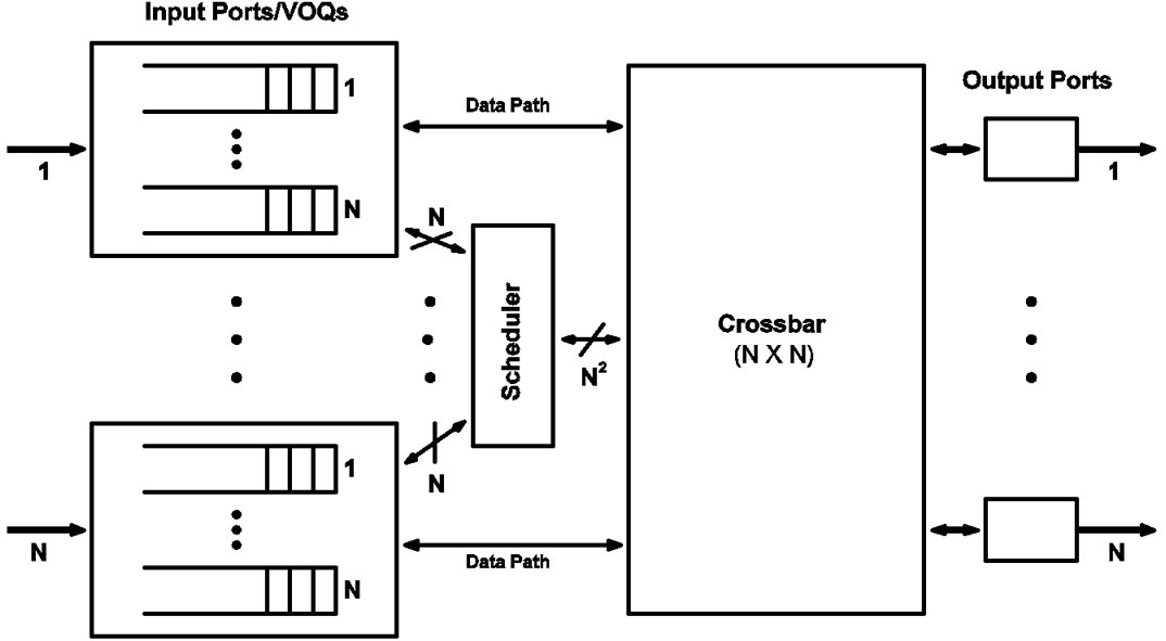 (b)
(b)
Figure 1. IQ switch fabrics. (a) An SRA architecture. It has distributed arbiters. (b) An iterative architecture. This typically has a centralized scheduler.
Traffic feeds up to one cell into the fabric at each input port every time slot of the line timing. If traffic exits the switch one cell at each output port every line timing slot if the output port is not empty, we say that the switch achieves full throughput (100%) [1].
In an SRA architecture (Figure 1(a)), for each output port, there is an arbiter that keeps track of the input ports having packets destined to it and their order of arrival. Those arbiters can be placed near the input ports to keep track of VOQ status easily. At each time slot, the arbiter grants a send to the input whose cell arrived the earliest. There is no memory existing for arbitration at an output port. Neither is there backpressure applied from the output ports. Backpressure is needed by many CIOQ architectures. Backpressure involves sending signals toward input ports when certain congestion thresholds are crossed in the queues at the output ports. Backpressure exerts flow control. No backpressure usage is a distinct feature of our architecture.
A crossbar is nonblocking and has a unified selfrouting algorithm to switch cells at its crosspoints as needed. Fabric scheduling is to arbitrate how the cells access the crossbar in an orderly fashion so as to maximize the crossbar utilization in a time slot.
Our first architecture uses the same crossbar as any iterative switch fabric. Our second architecture has a crossbar that is not entirely the same. The architecture is thereof called “multiple-multiplexer switch”. In addition, the VOQs at an input port are operated and connected to the crossbar differently between the two architectures. Architectural details will be discussed in Section 7.
4. The SRA Algorithm
SRA stands for single round-robin arbitration. Each output port uses a round-robin arbiter to select the input port to send in a time slot. PIM, iSLIP, and DSRR all have round-robin arbiters at both the input and output ports. SRA has several significant advantages. In this section, we describe the algorithm and then analyze its properties that make it simple, fast, and scalable. The IQ switch architecture supporting SRA is illustrated in Figure 1(a).
4.1. Description
Let G'(V', E') denote the bipartite graph defined as follows: V' = V'1 ∪ V'2, V'1 = {VOQi,j|1≤i, j≤N}, V'2 = {Oj|1≤ j ≤ N}, and E' = {(VOQi,j,Oj) | VOQi, j(t) > 0, 1 ≤ i, j≤N}. We call G' the modified I/O mapping graph. The SRA algorithm is designed to find a maximum matching in G'. Note that G' is different from G defined in Section 1 and the matching is done differently over G' than over G.
SRA is not iterative. It selects a set of up to N cells to send to up to N outputs in a single time slot. Each cell goes to a different output. In theory, these cells can come from one, N, or any other number of inputs. That is, each input can send up to N cells in a time slot. This is where SRA differs from existing algorithms which allow each input to send at most only one cell out in each time slot. Apparently this increases efficiency since there is little reason not to let the input send more than one cell in a time slot when other inputs have no cells to send.
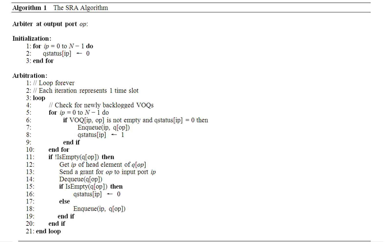
The pseudocode of the SRA algorithm is shown in Algorithm 1. In the pseudocode, the notation qstatus[ip] represents whether the VOQs at input port ip is empty or not. The notation IsEmpty(q[op]) represents whether the queue at the arbiter for output port op is empty or not. The notation Enqueue(ip, q[op]) means to add the number of input port ip to the tail of the queue at the arbiter for output port op, whereas Dequeue(q[op]) means to remove the head element from the queue at the arbiter for output port op.
The SRA algorithm works as follows:
(1) At the outputs. Each output arbiter maintains a again into the tail of the status queue, else the status element for that input is gone.
(2) At the inputs. Upon receiving a grant, the input checks if the corresponding VOQ is to become empty if the cell has been sent. If yes, it sends a status signal to the output arbiter indicating the VOQ is to be empty, so the output arbiter will not keep an element for this input in its FIFO queue again. Then the input port sends a cell to the crossbar with the designated output information. The input sends status information about any of its VOQs to the corresponding output (arbiter) only when the VOQ changes from being empty to having a cell arrived and from having cells to becoming empty.
4.2. Complexity
In each time slot (a cell time), a fabric scheduler must perform a matching and synchronously switch on and off the crosspoints of the crossbar to send up to N packets out. High line rates ever stringently require a scheduling action to be prompt. Since SRA finds a maximum matching in a single iteration, it is capable of fast scheduling actions. Its time complexity is only O(1) since all the operations in the algorithm take constant time to finish. On the other hand, an iterative algorithm doing multiple iterations would be too slow to support high line rates.
SRA needs fewer messages to operate than an iterative matching algorithm. The number of exchanged messages a port has to process is equal to the product of N and the number of service levels. Consider the case of best-effort service only. For each matching, an output arbiter sends only one grant message, an input can send up to N status messages out if the status of all N VOQs changes. Over the entire fabric, there are at most N2 messages exchanged between the inputs and the outputs. Unlike SRA, iSLIP needs N2 requests, N2 grant notifications, and N accepts for each iteration. For iSLIP to converge, at least logN iterations are needed. Thus iSLIP needs a total of (2N2+N) logN messages. PIM and DSRR each need about the same number of messages as iSLIP.
It may be more accurate to compare the information bits exchanged than analyzing the amounts of messages sent by SRA and iSLIP. For SRA, N grants will be sent from output ports to input ports. Hence a total of N2+N bits are exchanged. For iSLIP, only the information bits from the input ports to the scheduler and back to the input ports should be considered. That will be also N2+N bits, the same as for the other iterative algorithms. Of course SRA only does one iteration but the others need logN iterations.
In matching over G', in a time slot, each input can be mapped to multiple outputs, but each output is mapped to one input or is not mapped when there is no traffic destined to it. Since only the arbiters decide and send grants, this matching can be regarded as output constrained (and input unconstrained). Yet iterative matching over G involves both input and output ports for actions of request, accept, and grant, and is thus both input and output constrained.
5. Performance Analysis
We first show that SRA matches the maximum number of inputs to the maximum number of outputs in each time slot. We then show that SRA sustains 100% throughput and that it is fair.
Theorem 5.1. SRA always finds the maximum matching in G'.
Proof. Let k(t) be the number of nodes in V'2 of G' with non-zero degree at time slot t, and M' be any matching of G' at time slot t. By the definition of M', k(t) ≤ |M'|. SRA guarantees a matching M* such that its size is exactly k(t).
Alternatively, because there are N independent (disjoint) subgraphs in G' each of which corresponds to and matches a particular output port, SRA guarantees to find a maximum matching in each time slot.
That an input port can send m (1 ≤ m ≤ N) cells and the input ports altogether are allowed to send no more than N cells in a time slot is called the free rule. There exist analytical studies of throughput under the free rule [22-25]. These studies assume that traffic arrival is i.i.d. Bernoulli with uniformly distributed destinations and found that throughput can be 100% if the load does not exceed 1.0.
Since SRA is a free-rule scheduling policy, so in theory it should sustain 100% throughput. In fact, we can show that SRA does so irrespectively of the traffic arrival patterns.
Theorem 5.2. SRA sustains 100% throughput.
Proof. Each input port keeps up to N VOQs. Assume that all the VOQs destined to the same output port j at the input ports bid for transmission in a time slot t. Let γ be the throughput of these VOQs. Note that γ is equal to the overall throughput. Let Nj be the number of HOL packets at all the VOQs destined to output j in t. The total number of HOL packets blocked at the VOQs in t is
Nb=Nj−ε(Nj) (1)
where ε(Nj)=min(1,Nj). More specifically, function ε is defined as
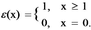
In each time slot SRA sends up to N cells out and there can be up to N cells arriving. Thus E[ε(Nj)]=γ in steady state. Taking expectation of (1) gives
γ =E[Nj]−E[Nb] (2)
Let M be the total number of unblocked VOQs in t. Then
M=N−Nb (3)
By flow conservation, we have
E[M]ρ=γ (4)
where ρ is the probability that one of the M unblocked VOQs gets a new cell to arrive in t. Taking expectation on both sides of (3) and using (4), we obtain
E[Nb]=N−γ/ρ (5)
Let N'j be the number of HOL packets with destination j in time slot t + 1. Let Aj be the number of HOL packets with destination j arrived at the M sending VOQs. We have the following dynamic equation:
N'j=Nj−ε(Nj)+Aj (6)
Then we can obtain the following mean-value equation as in Appendix A of [22]:
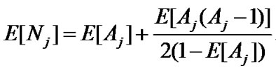 (7)
(7)
For large values of N, Aj can be approximated by a Poisson distributed random variable. This step follows the proof by Karol et al. in Appendix A of [26] which shows that as N → ∞, the steady-state number of HOL packets at the VOQs destined for an output in each time slot becomes Poisson. We can obtain
E[Aj]=E[ε(Nj)]=γ (8)
E[Aj(Aj−1)]=γ2 (9)
Using (8) and (9) and substituting (5) and (7) into (2), we obtain the throughput formula by setting ρ=1:
 (10)
(10)
Equation (10) implies that when N→∞, throughput is 1. Actually when N is finite, (10) still gives a very close approximation to the optimum value. For instance, when N = 32, γ = 0.992.
Theorem 5.3. SRA is fair.
Proof. We consider a loading scenario more general than uniform i.i.d. Bernoulli. Assume that the loading rate at each input is the same λ and is admissible. Admissible traffic does not oversubscribe any input or output port. Let λij be the loading rate of traffic going from input i to output j. We haveλij=δλ where δ is the fraction of λ for traffic going from input port i to output port j. Let μij be the portion of the service rate μ at output port j that serves the traffic of λij. Thenμij=δμ
By the admissible rule, the rate of traffic arriving at port j from all the input ports combined does not exceed μ. Also, the output arbiter works in a round-robin fashion serving each input port that has a cell in turn in each time slot. By Theorem 5.2, traffic of λij will receive its fair share of service. Hence we have the above equation. Also, in steady state, λ = μ. Thus we obtainλij=μij
The above equation holds for any given time period. In a time period of m time slots, an arbiter j ensures λijm time slots granted to input port i, since each arbiter works round-robin on the status FIFO queue and any backlogged input port is re-enqueued after it has got a turn to send. Therefore, SRA is able to allocate the available service rate to all input-output pairs in proportion to their offered loads in any given time period.
Note that SRA is fair per VOQ or fabric-wide. Subsequently, per-port fairness is also guaranteed.
6. Performance Evaluation
We simulated SRA against PIM, iSLIP, and DSRR in various traffic conditions. Performance metrics are cell delay and throughput vs. offered load. Offered load is the number of cells per time slot per input. The results show that SRA outperforms the other three and provides high throughput and low delay.
6.1. Uniform Traffic
We first tested the performance of SRA when the incoming traffic is i.i.d. Bernoulli with destinations uniformly distributed. Since SRA works in one iteration, we first ran PIM, iSLIP, and DSRR for only one iteration. We then ran them for four iterations. In all these cases, N is 16. That is, the switch size is 16 × 16. We used the same traffic pattern for all four schemes.
Figure 2 shows cell delay vs. offered load. When the load is 20% or less, all four schemes perform the same. But when the load increases, their performances are significantly different. When the load is less than 60%, PIM, iSLIP, and DSRR show about the same performance, while SRA is 6 times faster than the other three. When the load exceeds 60%, PIM becomes instable and iSLIP performs much better than DSRR. At this time, SRA outperforms the others by many times over. Compared to PIM and DSRR, iSLIP works much better. In terms of throughput, the situation is similar as shown in Figure 3.
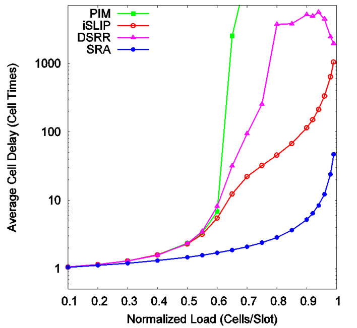
Figure 2. Cell delay under uniform traffic (one iteration).
In the case of four iterations, PIM, iSLIP, and DSRR all perform better than with one iteration. But compared to SRA, they are still off by a few times as shown in Figure 4 and Figure 5. The differentiation becomes the clearest when traffic load reaches 96% and higher. The advantage of DSRR over iSLIP is now obvious. DSRR approaches PIM very closely overall. Both PIM and DSRR perform better than iSLIP. The delay values for PIM, iSLIP, DSRR, and SRA at load 99.5% are 217, 451, 265, and 91 cell times respectively. SRA outperforms the others by 3 to 5 times at all load values.
Although PIM works better than iSLIP, PIM has its problems as discussed in [4]. That is why iSLIP has been adopted in many commercial switches. First, randomness is hard to implement at high speed since ran-
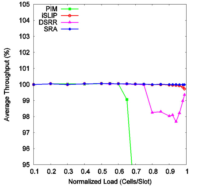
Figure 3. Throughput under uniform traffic (one iteration).
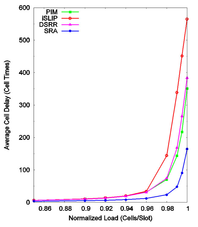
Figure 4. Cell delay under uniform traffic (four iterations).
dom selection has to be made over a time-varying set of elements. Second, PIM can be unfair especially when the inputs are oversubscribed. Third, PIM converges only after several iterations.
Work on PIM is recent as in 1999 when Nong et al. proposed an analytical model and derived closed-form solutions on throughput, mean cell delay, and cell loss probability [27]. They found that the maximum throughput of the switch exceeds 99% with just four iterations under i.i.d. Bernoulli traffic with cell destinations uniformly distributed over all the output ports. Our simulations show the same throughput performance for PIM. Our simulations also show that on throughput DSRR is about the same as PIM, but iSLIP is off rather markedly at high load. SRA’s throughput is closest to 100% among all four algorithms at all times.
6.2. Bursty Traffic
We modeled bursty traffic using interrupted Bernoulli process (IBP). IBP is the discrete version of interrupted Poisson process. IBP is similar to two-state Markovmodulated Bernoulli process, exponential on/off process, and Pareto on/off process. Switch size is again 16×16.
IBP has two states (on and off) and is characterized by three parameters α, p, and q. In each time slot, if the current state is on, the state remains on in the next time slot with probability p; if the current state is off, the state remains off in the next time slot with probability q. In the on state, a cell arrives in a time slot with probability α. The length of on state, X, and the length of off state, Y, have geometric distributions:
P{X=x}=(1−p) p(x−1)
P{Y=y}=(1−q) q(y−1)
The mean arrival rate or offered load, ρ, is
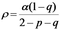
Average burst length is
In each burst period, arrived cells all go to the same destination. Thus b measures how bursty the traffic is. In our simulations, we set b=128 cells and α=1. When α is set, p is set. To get various loads, we just vary the value of q.
As shown in Figure 6, SRA is faster than the other three over all loads. PIM, iSLIP, and DSRR were run for four iterations. At load 95.92%, the delay values are 4453, 5357, 4597, and 2391 cell times for PIM, iSLIP, DSRR, and SRA respectively. In all times, PIM, iSLIP, and DSRR are very close to each other, and SRA works 2 to 3 times faster than them.
Figure 7 shows how each performs in terms of throughput. Again, SRA maintains the highest throughput under all loads. Its throughput dips when load passes 90% but still less than the rest. Thus SRA is the most stable at providing high throughput.
6.3. Effect of Switch Size
The performance of iSLIP degrades considerably as switch size increases as shown in [4]. The switch slows down a time when N doubles. We saw little slowdown with SRA when switch size increases.
We ran a few simulations on an N × N switch with N being 4, 8, 16, 32, and 64. Traffic is i.i.d. Bernoulli with uniformly distributed destinations. As shown in Figure 8" target="_self"> Figure 8, when N = 4, cell delay is the smallest. But when N takes larger values, cell delay remains just about the same. That implies that the SRA scheduling scheme provides the same efficiency regardless of N. Thus SRA is scalable.

Figure 5. Throughput under uniform traffic (four iterations).
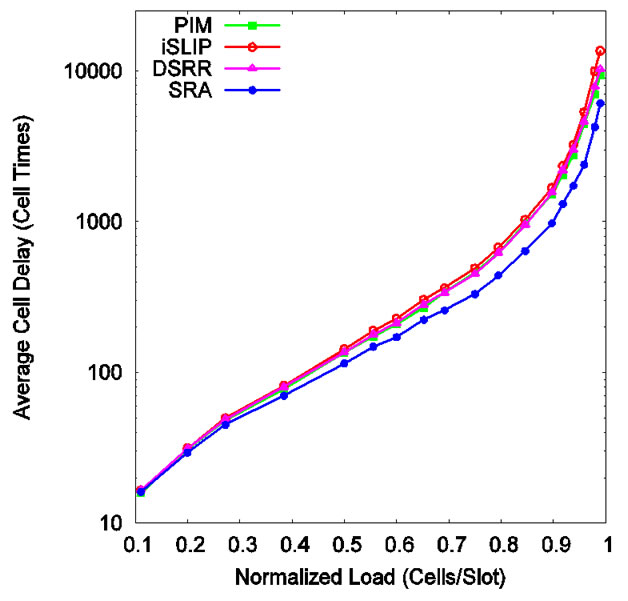
Figure 6. Cell delay under bursty traffic.
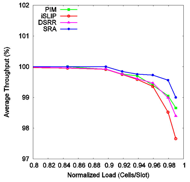
Figure 7. Throughput under bursty traffic.

Figure 8. SRA cell delay as a function of switch size (uniform traffic).
6.4. Input Blocking
Consider that the switching fabric used is a conventional unbuffered N × N crossbar, as in our first hardware architecture described in Section 7. SRA requires an input port to be able to occasionally transmit multiple cells in a time slot, each cell to a different output port. Assume that an input port transmit k (1 ≤ k ≤ N) cells in a time slot in such a situation. We call k cell multiplicity. Contention of reading data at the same time from the same input memory for multiple outputs is called input blocking. Our simulations show that the occurrence of input blocking is very rare and indeed negligible.
The maximum input blocking delay occurs when N reads have to be performed at one time. For a given input traffic pattern, the probability of this occurrence is zero under SRA. We did simulations for an N × N switch under full load of uniform i.i.d. Bernoulli traffic and IBP traffic when N is 16, 64, and 128. Table 1" target="_self"> Table 1 shows the frequency data we obtained. An input port can send zero, one, or multiple cells in a time slot. When a send involves multiple cells, multiple reads to the same input memory, hence input blocking, occurs. Frequency of a cell multiplicity is calculated by dividing the number of sends of that particular cell multiplicity with the total number of sends during the simulation duration.
The simulations indicate that k tends to be far smaller than N. The chance for input blocking to happen at all is also low. Specifically, the data in Table 1" target="_self"> Table 1 show that for N = 64 the occurrence of k > 2 is about 7% in the worst case. That k > 5 virtually does not occur. The probability is 7.81 × 10⁻⁷ for k = 8 and 0 for k > 10. Most input ports send only one cell or send none for a time slot. Some send two. Thus input blocking is slight. Figure 9" target="_self"> Figure 9 shows graphically the frequency of multiple reads when the load is full (1.0) for uniform Bernoulli traffic. The above property of low k holds true indifferently of N. Our simulations show that k is nearly unchanged when N is 16, 64, and 128 under the same uniform and bursty traffic conditions.
7. Switch Fabric Hardware
In this section, we discuss how to implement the SRA algorithm in hardware. We propose two alternative architectures that differ in the queuing structures and the crossbars used. Both architectures use the same SRA arbiters. The first architecture uses the same VOQs organization and the same crossbar as in a conventional
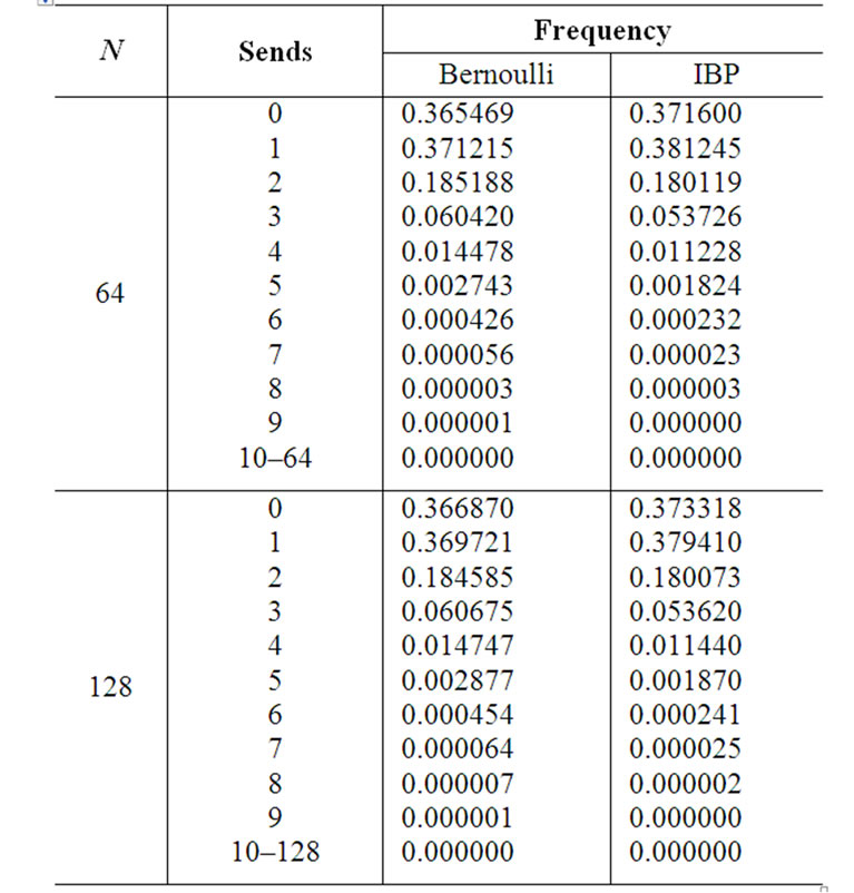
Table 1. Input blocking occurrence.
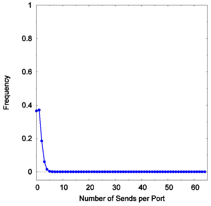
Figure 9. Frequency of input blocking occurrences. N=64. Full load of uniform Bernoulli traffic.
iterative switch fabric. The second uses a different queuing structure and a crossbar that is designed specifically for implementing the SRA algorithm. Compared to conventional switch architectures that work for iterative matching algorithms, the SRA architectures are simpler and hence more effective in terms of area and power.
SRA has to perform certain operations due to input blocking although their occurrence is rare. The distinctive operations of SRA in each time slot are: 1) each input must do k reads instead of a single read; 2) up to k cells must be carried on a link to the crossbar; and 3) at the crossbar these cells must be split onto separate inputs. As we have discussed in Subsection 6.4, cell multiplicity k incurred by SRA is low. Thus these peculiar operations can be implemented in hardware with adequate simplicity, as in our two architectures.
7.1. Queuing Structure and Crossbar
As we have mentioned already, the two architectures we are proposing differ mainly in the queuing structure and crossbar each uses. Here we discuss the two architectures and how they are distinguished by their queuing structure and crossbar. We call the two uses of queuing structure and crossbar roughly as designs.
7.1.1. Design I
This design uses the vintage queuing structure and square crossbar that have been used for iterative matching algorithms since certainly iSLIP [4]. But, of course, it uses the much simpler SRA arbiters. This design can overcome input blocking. The architecture is shown in Figure 10.
With this design, input blocking may simply be solved in this way: Whenever there is more than one cell to be sent by an input port in a time slot, make that time slot a little bit longer, enough for the multiple reads to complete. In fact, this may be a very feasible solution.
This solution is to allow each input port to send all k cells in a time slot. Thus, SRA inflicts no cell loss which is expensive. This is workable since k is never more than 10, and to make k reads causes a negligible extra delay than one read. It might be worth noting that the delay can be negligible mainly owing to fast memories and the high rate within the switch.
Input blocking would be a nonissue if the input port memory is capable of concurrent read. Should the memory technology be unavailable, other means must exist to mitigate the delay.
Memories supporting concurrent reads are being made. The SigmaRAMTM memories of synchronous SRAMs had been planned for quite some time that will be capable of fast, random, multiple reads [28]. Current speed of existing SRAMs is as fast as 2 ns per operation with a clock rate of 333 MHz and a 24 Gbps throughput. Operations for mostly reads include access to look-up tables and parameter memory (e.g., QoS parameters, congestion avoidance profiles, min/max bandwidth limits). For these operations the common I/O SigmaRAM products provide very high bandwidth per pin and total memory bandwidth. The faster the memory speed, the less the impact of input blocking on fabric delay.
High-speed fabric rate diminishes the delay of input blocking. Memory speed needed to support the high data rate also abates the effect of input blocking. Operations of multiple reads cause only negligible extra delay. For a
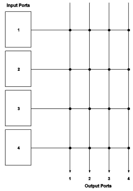
Figure 10. A 4 × 4 switch fabric that uses a square crossbar and contiguous memory for all VOQs at each input port. There is one data link (horizontal line) from an input port to the crossbar.
40-Gbps fabric, getting one 53-byte cell out of the input memory would take about 11 μs. Simulations done on a real 40-Gbps switch fabric show that extra input blocking delay is merely 0.1 to 0.2 μs [29]. The fabric has 128 ports and carries IMIX traffic. The delay is incurred by doing up to 128 reads from the input memory at the same time. That is about 1% of the delay to perform just one read.
With SRA, speed gain appears to outweigh speed loss due to possible input blocking. SRA gets N cells sent to the outputs by simply letting the queue head element at the output to send and sending one grant signal back to the inputs. Using an iterative matching scheme, this process would take many iterations of request, grant, and accept with numerous signals sent. SRA removes this complexity at the expense of a much smaller delay of multiple reads. In view of this and the other aforementioned facts, input blocking in this context is a benign tradeoff for simplicity and speed.
With a conventional crossbar, each input port needs only one wire to connect to the crossbar by following the shortest path. The crossbar, being self-routing, will route the cells from different input ports to their destinations. Using one wire is workable and the crossbar is necessary because an input port can send at most one cell to one arbitrary yet distinct output port. The cell on the connecting wire can be going to any of the N output ports.
With SRA, an input port can send multiple cells going to different output ports in a time slot. The crossbar needs to direct the multiple cells arriving to it so that the cells go to separate inputs of the crossbar with correct synchronization.
7.1.2. Design II
This new switch architecture (Figure 11) is different from Design I. It uses separate memories for the VOQs and also a special crossbar. It is so suited to combat input blocking.
At an input port, traffic arrival is normalized to be one cell per time slot. Each input line card has N separate memories, one for each VOQ. An input line is connected to a 1×N demultiplexer, which distributes incoming packets (segmented to cells) to different VOQs. Since each VOQ works over a separate memory, it needs a separate transmitter. Multiple transmitters need to transmit cells from corresponding VOQs simultaneously in a time slot to tackle input blocking. Each input port needs N transmitters.
In this architecture, an input port and hence VOQk,j, where 1 ≤ k ≤ N, are connected to output Oj via an N × 1 multiplexer (MUX). The N × N crossbar consists of N MUXs of size N × 1. As such, the architecture may be better called a multiple-multiplexer (MMUX) switch.
As shown in Figure 11, this fabric has the following feature: At any time, each output port j is connected to at most one VOQ at input i (VOQi,j) and each input port can have up to N VOQs connected to output ports. Note that such a pattern is exactly a maximum matching of G' found by SRA. Clearly, the MMUX crossbar has O(N2) crosspoints, resulting in a complexity of O(N2), which is the same as the complexity of a conventional N × N crossbar.
Besides being suitable for SRA, this new fabric has two additional advantages compared with conventional crossbar. First, the MMUX crossbar has a reduced diameter, which is the maximum number of crosspoints on an input-output path. With N N × 1 MUXs, the diameter of the crossbar, which depends on the diameter of an N × 1 MUX, is N, whereas the diameter of a conventional crossbar is 2N. If each of the N N × 1 MUXs were implemented as a (self-routable) binary tree, then the diameter of this crossbar would be logN. Implementing a crossbar by electrical switching elements, the reduced diameter corresponds to smaller signal delay. If each crossing point is implemented by an electro-optic switching element, then the reduced diameter corresponds to less crosstalk and power loss. In fact, crosstalk virtually does not exist in optical implementation of the MMUX crossbar because there do not exist two connection paths in the fabric sharing a crosspoint at any time according to SRA.
The second advantage of this fabric is that it has a distributed control, as a result of the distributed feature of SRA. In the fabric, cell scheduling and transmission for each output port is totally independent of other output ports. Thus, the fabric can be considered as N subsystems, each consisting of all the VOQs designated to a particu-
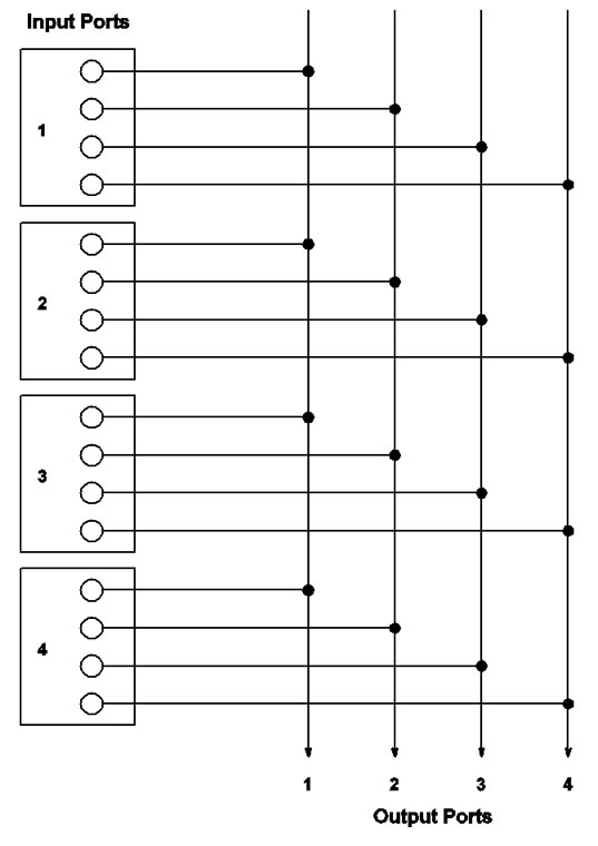
Figure 11. A 4 × 4 MMUX switch fabric in which each VOQ can get a link to an output port. The links (horizontal lines) are data lines.
lar output port and a MUX that connects these VOQs to their corresponding output. Then, the problem of synchronizing the entire fabric is reduced to synchronization of independent subsystems. This feature is particularly important when N is large.
The MMUX crossbar is different from the standard square crossbar. In this crossbar, each input can send 1 or more cells per time slot, and each output can receive none or 1 cell per time slot. In a standard crossbar each input/output can send/receive none or 1 cell per time slot. The MMUX crossbar is more powerful than a standard crossbar; it can do everything a conventional crossbar can do, but the converse is not true.
The question is how to reduce the usage of transmitters to make the hardware more scalable? As described in Subsection 6.4, simulations indicate that cell multiplicity k is low: an input port virtually never sends more than 5 cells in a time slot even for N=128, a reasonably large switch size. To exploit this property, the following approach can be taken. The resulted structure can be regarded as a variant to Design II proper.
For each input, instead of using N transmitters, use k transmitters. The total number of transmitters is now kN, much smaller than N2. As before, each input has N single port memory modules, one for each VOQ. But each input needs an N × k switch and a k × N switch. The N × k switch is used to select and connect any k VOQs to the inputs of k transmitters. The k × N switch is used to connect the outputs of k transmitters to k outputs corresponding to the k selected VOQs.
The advantage of this approach is reduced number of transmitters and no memory access speedup. The disadvantage is additional cost due to the N × k and k × N switches. Total cost is 2kN2 = O(N2) crosspoints. But this may be worthwhile considering how many transmitters are saved.
7.2. Arbiter Structure and Layout
The hardware structure of an iterative matching scheme as that shown in Figure 21 of [4] and Figure 1 of [30] has two layers of arbiters: one consists of N grant arbiters and the other N accept arbiters. The arbiters of both layers have to work together to coordinate and phase the grant or accept actions. As such, all of the arbiters must be placed together, constrained by a state memory and update logic to receive requests from the VOQs next to the input ports, and by a file of decision registers next to the cross bar, thus forming a centralized unit. An arbiter itself typically takes on a round-robin structure (made of priority encoders) as in [4,31,32] or a tree or binary tree structure as in [30,33]. All have a O(logN) gate delay and consumes O(N) gates.
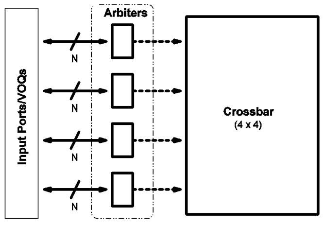
Figure 12. SRA arbiter layout. The dashed arrows indicate that data cells go from the input ports to the crossbar separately.
SRA needs only one layer of N arbiters as shown in Figure 12. The arbiters work in complete parallel, without any coordination or centralized arbitrating hardware. Thus they can be placed in a chip distributedly. Moreover, the arbiter itself implements only a FIFO queue and the associated operations such as enque and deque. The FIFO queue implies round-robin, whereas the discrete arbiters embody overall scheduling. As pointed out in Subsection 4.1, the size of the queue is N.
In Figure 12, the paths from input ports to the arbiters are independent of the data traffic paths as shown in Figure 11. There is no communication between the arbiters and the crossbar. Also, the layout applies to both cases where one wire (as in a conventional iterative fabric) or 4 wires (as for the MMUX fabric shown in Figure 12) are used to link an input port to the crossbar.
In hardware, a FIFO may consist of a set of read and write pointers, storage, control logic, and read and write lines. The read/write pointers are used to track the head
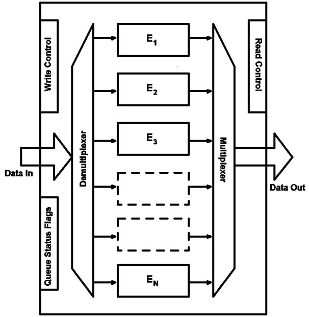
Figure 13. Hardware schematic of a FIFO device that can be used as an SRA arbiter. The elements may actually reside in contiguous memory.
and tail of the queue for deque and enque operations and generate queue status flags such as Empty and Full. Read and write lines are used to read out and write in data. In relation to the SRA algorithm, deque corresponds to grant and enque to update of input state. Each will need only one wire (data line) for proper connection to each input port. Storage may be SRAM, flip-flops, and latches. Control logic or FIFO controller contains read and write clocks, enforces synchronization, and drives the read and write pointers. A FIFO “node” needs to store only the number of the input port which, for instance, can be 8 bits to support 64 ports. The complexity of the arbiter: gate delay O(1) and number of gates O(N).
FIFO hardware implementations are numerous. Figure 13 shows a hardware schematic of a FIFO device that fits the design features stated above. It is drawn in reference to Figure 1 of [13]. Work [34] shows a FIFO design that has more features than needed for an SRA arbiter, but is a good source for device details. In Figure 13, the data input port can be considered as consisting of the N wires coming from the N input ports, and the data output port N wires going to the input ports. The data input demultiplexer writes data into an element pointed to by the write pointer, whereas a data output multiplexer can be configured to read data from an element pointed to by the read pointer. Each of the elements marked E1, · · ·, EN needs to store logN bits. The elements can be in one contiguous piece of memory. The blocks for read, write, and queue status flags can be integrated into one controller. The design in [34] shows how all N FIFOs (arbiters) can be put in a single device that has nearly the same structure as what is shown in Figure 13.
In essence, the SRA arbiter is simpler. The arbiters needed for SRA scheduling are disparate. They can be placed in one chip with simple supporting components to perform overall scheduling.
7.3. Scalability
In Subsection 4.2, we showed that SRA can support high line rate and uses less auxiliary messages to make arbitration decisions. These properties plus the ones below indicate that SRA is more scalable than conventional iterative fabrics.
First, the SRA scheduler can expand to handle very large N without adversely affecting speed. This is demonstrated by our simulations as shown in Subsection 6.3. In contrast, an iterative algorithm degrades considerably in speed when N increases. The degradation is caused by the very arbitration logic of the algorithm more than by its iterations.
Second, SRA does not need constant feedback from the outputs about their readiness. CIOQ switches need this feedback for the outputs to make granting decisions. Therefore, the SRA scheduler need not be in a central location. The output arbiters can be placed near the input ports such that the input status updates can be done more easily. These output arbiters can be spatially distributed and execute in parallel (Figure 1(a)).
Third, SRA can more rigorously ensure scalability. Between SRA and a conventional iterative fabric, given the same circuit complexity, SRA has increased scalability, as we elaborate below.
Let Ts be the time of one round (iteration) of arbitration. An iterative algorithm takes TslogN time for one time slot, while SRA takes Ts time for one time slot. Consider that a time slot takes time Tc. In order for an iterative algorithm to work, it must meet the following condition:
Ts logN ≤ Tc. (11)
Since Tc is constant, when N is large, (11) cannot be satisfied. At high line rates, Ts must decrease, (11) becomes harder to satisfy. But SRA needs only to satisfy Ts ≤ Tc.
SRA completes an arbitration in a single round, so the time required for scheduling for one time slot is reduced significantly. Thus, SRA is more scalable in the sense of satisfying stringent real-time requirement.
In particular, the SRA arbiter circuit is less complex than the other components in the two SRA fabrics. The fabrics are thus scalable by the criterion of Li, Yang, and Zheng that the arbitration circuit should not be more complex than the interconnect [35].
Many scheduling algorithms we referenced in Section 2 require complex hardware if they are implementable at all. Li et al. [35] proposed to measure the complexity of a scheduling algorithm in an IQ switch by its structural complexity in hardware against that of the interconnect. They showed that a scheduler not more complex than any nonblocking interconnect can perform as well as non-scalable schedulers. Structural complexity is measured by the number of links (wires) used in the hardware in terms of switch size N.
7.4. Speedup and Egress Memory
SRA requires little speedup if any at all. Ideally, a cell gets out at an output each cell time of the line rate. There are no holdups anywhere in the fabric. The operation that takes the most time is sending the grants to the inputs and for the inputs to pass out the cells. It takes constant time for an output to dequeue the head element in the FIFO queue.
Factoring in input blocking, the speedup of this architecture S < 1 + 10−6 ⇒ S = 1. Thus it is fair to say that this architecture operates in line rate and needs no speedup. Note that this speedup is lower than the best and commonly believed speedup value of 2 for IQ switching.
In contrast, PIM, iSLIP, and DSRR complete a matching in logN iterations. This needs complex hardware to sustain small speedup. SRA completes a matching in one iteration with much fewer messages. The hardware is less complex yet to support no speedup.
SRA makes the fabric to be strictly scheduled. The scheduled fabric is a pull-type one as opposed to a pushtype one. In this fabric, cells at the inputs wait to be explicitly summoned by the outputs into the fabric. No backpressure from the outputs is needed. Complete states of the VOQs at each input are made available to the output arbiters. Therefore, egress memory is not needed by arbitration in an SRA fabric. SRA is a one-hop scheduling scheme. As line rates increase, egress memory adds significant cost and latency in the system’s datapath. Egress memory could be removed when fabric and traffic scheduling is all done at the input ports.
The following is particular of the MMUX architecture. As shown in Subsection 7.1, this architecture has separate memories and transmitters at the input ports. There is no conflict in sending cells from VOQs to output ports. In other words, at input line rate, a cell can be read and sent out of its VOQ without speedup. Thus no memory access speedup and no transmission speedup are required. However, there is an added hardware cost of N2 transmitters for Design II proper and of kN transmitters and O(N2) switch crosspoints for the variant of Design II.
7.5. Compared to the Knockout Switch
As we have alluded to in Section 1, OQ scheduling requires N writes (plus N reads if the output ports are under one shared-memory) in one time slot. SRA transforms the N writes of OQ into N reads. A read operation is much easier to perform and needs minimal hardware support. Thus, SRA reduces the complexity while approaching OQ in speed. Note that actual OQ switches do exist despite the multiple-writes problem.
The Knockout Switch [36] is an example OQ switch which combats the multiple-writes problem by using concentration circuit. The multiple-writes problem here is seemingly similar to input blocking. In fact, the frequencies of cell contention accrued by traffic flow in the Knockout and SRA switches are strikingly close. Coincidentally, this helps validate the correctness of our algorithm and simulations. Below we discuss the design of the Knockout and compare its performance to SRA’s.
The Knockout uses an N × L concentrator at each output port. The concentrator connects N input ports and fan them in to L outlets at the output port such that in a time slot at most L cells can be admitted although there can be N cells arriving each from one input port. The possible remaining N − L cells are dropped, causing a loss probability. The purpose of selecting only L cells in each time slot is to reduce the number of output FIFO buffers and the control circuit complexity. However, the output port has to be able to do L writes to buffer the L cells since only one cell can exit the output port in a time slot. It has been shown that a cell loss probability of only 10−6 is achieved with L as small as 8, regardless of switch load and size [36].
In comparison to the Knockout, under SRA, an input port only needs to do k reads in a time slot. Moreover, our simulations indicate that the probability for k=8 is 7.81×10⁻⁷ and the probability for k > 10 is zero, regardless of switch load and N. In the mean time, SRA and the scheduling scheme used by the Knockout both have constant time complexity. Therefore, SRA has several advantages over the Knockout.
Finally, it is worth concisely noting the two differences between the Knockout and SRA. A fundamental difference is that the Knockout is an OQ switch and SRA is for IQ switches. Secondly, unlike the Knockout, an SRA fabric does not contain concentration circuits and does no concentration because in any given time slot, only one of the N input ports connected to an output port will have a cell going through.
8. Conclusions
This paper proposes a new scheduling scheme which finds a maximum matching of a modified I/O mapping graph in a single iteration and shows that the proposed scheme achieves 100% throughput and has much lower delay than the conventional iterative scheduling schemes. Implementation issues are discussed and two new switch fabrics are presented.
The major innovation of the SRA algorithm is that it considers the matching in G'. Hence, the switch architectures for SRA are different from that for the iterative algorithms which consider the matching in G. Both architectures hinge on the simple SRA arbiter. The SRA arbiter is much simpler than the arbiter used for iterative schemes. Each SRA architecture uses a set of SRA arbiters that operate in parallel with no interaction. It differs from a general IQ switch architecture which typically has the complex scheduler located in a centralized unit. The SRA switch fabrics are therefore simpler in hardware than an iterative fabric.
Other aspects that are new of the SRA architectures include:
•Removal of egress memory for arbitration.
•Use of the free rule in arbiting: an input port can send k cells at a time. Analysis and simulations all show that this makes SRA to find a maximum matching in a time slot without iteration.
•No backpressure usage. Iterative schemes use grant and accept functions to exert backpressure.
•Speedup for SRA S ≪ 2 cumulatively (virtually S = 1). This is easily calculated as we have shown in Subsection 7.4. This is a significant improvement over iterative schemes all of which require a speedup S ≥ 2, although the MMUX option has an added cost of transmitters.
•Hardware implementations are analyzed to be doable, simple, and efficient.
A switch implementing SRA can be regarded as an IQ switch because traffic is queued at the input ports and no egress memory is needed for arbitration. If buffering for packet reassembly is done at the output port, then egress memory for that is needed and the architecture would be better called a CIOQ switch. However, if the MMUX architecture is used, the switch would be better called a “MMUX-based IQ switch” to distinguish it from the common IQ switch that typically uses an iterative scheduler. We alluded to this in Subsection 7.1.2.
The benefits of using SRA include high throughput and low delay. Note that cell delays incurred by the iterative PIM, iSLIP, and DSRR in simulations would be much higher if the time spent on iterating the algorithms were taken into account. In addition, SRA is scalable and reduces the complexity of switching.
We hope SRA could serve as a design reference for IQ (or CIOQ) switches. Whether SRA can be useful to IQ switches with buffered crossbars, the other promising alternative to designing IQ switches, is yet to be investigated. Also, the SRA fabrics are best-effort architectures. Quality of service and multicast support merits further study.
9. Acknowledgements
This work is supported in part by NSF CCR-0309461, NSF IIS-0513669, HK CERG 526007 (HK PolyU BQ06B), NSFC 60728206, and NSF 0714057.
The code used for the simulations is based on the code authored by Prof. Ken Christensen of the University of South Florida. PIM and iSLIP results obtained with the initial code were validated against results shown in [37].
10. References
[1] N. McKeown, V. Anantharam, and J. Walrand, “Achieving 100% throughput in an input-queued switch,” in Proceedings of IEEE INFOCOM’96, pp. 296–302, March 1996.
[2] N. McKeown, A. Mekkittikul, V. Anantharam, and J. Walrand, “Achieving 100% throughput in an input-queued switch,” IEEE Transactions on Communications, Vol. 47, No. 8, pp. 1260–1267, August 1999.
[3] A. Mekkittikul and N. McKeown, “A practical scheduling algorithm to achieve 100% throughput in inputqueued switches,” in Proceedings of IEEE INFOCOM’98, pp. 792–799, March 1998.
[4] N. McKeown, “The iSLIP scheduling algorithm for input-queued switches,” IEEE/ACM Transactions on Networking, Vol. 7, No. 2, pp. 188–201, April 1999.
[5] N. McKeown, J. Walrand, and P. Varaiya, “Scheduling cells in an input-queued switch,” IEE Electronics Letters, Vol. 29, No. 25, pp. 2174–2175, December 1993.
[6] R. O. LaMaire and D. N. Serpanos, “Two-dimensional round-robin schedulers for packet switches with multiple input queues,” IEEE/ACM Transactions on Networking, Vol. 2, No. 5, pp. 471– 482, October 1994.
[7] A. Hung, G. Kesidis, and N. McKeown, “ATM inputbuffered switches with the guaranteed-rate property,” in Proceedings of IEEE ISCC’98, pp. 331–335, June 1998.
[8] M. Yang and S. Q. Zheng, “An efficient scheduling algorithm for CIOQ switches with space-division multiplexing expansion,” in Proceedings of IEEE INFOCOM 2003, pp. 1643–1650, March 2003.
[9] H. J. Chao and J.-S. Park, “Centralized contention resolution schemes for a large-capacity optical ATM switch,” in Proceedings of IEEE ATM Workshop’98, pp. 11–16, May 1998.
[10] J. Chao, “Saturn: A terabit packet switch using dual round-robin,” IEEE Communications Magazine, Vol. 38, No. 12, pp. 78–84, December 2000.
[11] Y. Li, S. Panwar, and H. J. Chao, “On the performance of a dual round-robin switch,” in Proceedings of IEEE INFOCOM 2001, pp. 1688–1697, April 2001.
[12] C.-S. Chang, W.-J. Chen, and H.-Y. Huang, “On service guarantees for input-buffered crossbar switches: A capacity decomposition approach by Birkhoff and von Neumann,” in Proceedings of IEEE/IFIP IWQoS’99, pp. 79–86, May 1999.
[13] C.-S. Chang, W.-J. Chen, and H.-Y. Huang, “Birkhoff-von Neumann input buffered crossbar switches,” in Proceedings of IEEE INFOCOM 2000, pp. 1614–1623, March 2000.
[14] C. -S. Chang, D. -S. Lee, and C. -L. Yu, “Generalization of the Pollaczek-Khinchin formula for throughput analysis of input-buffered switches,” in Proceedings of IEEE INFOCOM 2005, Vol. 2, pp. 960–970, March 2005.
[15] J. G. Dai and B. Prabhakar, “The throughput of data switches with and without speedup,” in Proceedings of IEEE INFOCOM 2000, pp. 556–564, March 2000.
[16] A. Gourgy and T. H. Szymanski, “Tracking the behavior of an ideal output queued switch using an input queued switch with unity speedup,” in Proceedings of IEEE HPSR 2004, pp. 61–66, April 2004.
[17] S. Mneimneh, “Matching from the first iteration: An iterative switching algorithm for an input queued switch,” IEEE/ACM Transactions on Networking, Vol. 16, No. 1, pp. 206–217, February 2008.
[18] R. Panigrahy, A. Prakash, A. Nemat, and A. Aziz, “Weighted random matching: A simple scheduling algorithm for achieving 100% throughput,” in Proceedings of IEEE HPSR 2004, pp. 111–115, April 2004.
[19] V. Tabatabaee and L. Tassiulas, “Max-min fair self-randomized scheduler for input-buffered switches,” in Proceedings of IEEE HPSR 2004, pp. 299–303, April 2004.
[20] T. E. Anderson, S. S. Owicki, J. B. Saxe, and C. P. Thacker, “High-speed switch scheduling for local-area networks,” ACM Transactions on Computer Systems, Vol. 11, No. 4, pp. 319–352, November 1993.
[21] Y. Jiang and M. Hamdi, “A fully desynchronized roundrobin matching scheduler for a VOQ packet switch architecture,” in Proceedings of IEEE HPSR 2001, pp. 407– 411, May 2001.
[22] H. Kim and K. Kim, “Performance analysis of the multiple input-queued packet switch with the restricted rule,” IEEE/ ACM Transactions on Networking, Vol. 11, No. 3, pp. 478–487, June 2003.
[23] H. Kim, C. Oh, Y. Lee, and K. Kim, “Throughput analysis of the bifurcated input-queued ATM switch,” IEICE Transactions on Communications, E82-B(5), pp. 768–772, May 1999.
[24] C. Kolias and L. Kleinrock, “Throughput analysis of multiple input-queueing in ATM switches,” in Proceedings of the International IFIP-IEEE Conference on Broadband Communications, pp. 382–393, April 1996.
[25] K. L. Yeung and S. Hai, “Throughput analysis for inputbuffered ATM switches with multiple FIFO queues per input port,” IEE Electronics Letters, Vol. 33, No. 19, pp. 1604–1606, September 1997.
[26] M. J. Karol, M. G. Hluchyj, and S. P. Morgan, “Input versus output queueing on a space-division packet switch,” IEEE Transactions on Communications, COM- 35(12), pp. 1347–1356, December 1987.
[27] G. Nong, J. K. Muppala, and M. Hamdi, “Analysis of nonblocking ATM switches with multiple input queues,” IEEE/ACM Transactions on Networking, Vol. 7, No. 1, pp. 60–74, February 1999.
[28] SigmaRAM Consortium, SigmaRAMTM targets high speed networking applications, White paper, 2008. http://www.sigmaram.com/white paper.htm.
[29] G. Bracha, “Removing egress memory from switching architectures,” CommsDesign.com, February 2003.
[30] S. Q. Zheng, M. Yang, J. Blanton, P. Golla, and D. Verchere, “A simple and fast parallel round-robin arbiter for high-speed switch control and scheduling,” in Proceedings of the 45th IEEE Midwest Symposium on Circuits and Systems (MWSCAS-2002), Vol. 2, pp. 671–674, August 2002.
[31] P. Gupta and N. McKeown, “Designing and implementing a fast crossbar scheduler,” IEEE Micro, Vol. 19, No. 1, pp. 20–28, January/February 1999.
[32] Y. Tamir and H.-C. Chi, “Symmetric crossbar arbiters for VLSI communication switches,” IEEE Micro, Vol. 4, No. 1, pp. 13–27, January 1993.
[33] H. J. Chao, C. H. Lam, and X. Guo, “A fast arbitration scheme for terabit packet switches,” in IEEE GLOBECOM ’99, Vol. 2, pp. 1236–1243, Rio de Janeiro, Brazil, December 1999.
[34] C. A. Karnstedt, B. L. Chin, P. Shamarao, and M. Montana, “Integrated circuit FIFO memory devices that are divisible into independent FIFO queues, and systems and methods for controlling same,” U.S. Patent 6,907,479, June 2005.
[35] C. Li, S. Q. Zheng, and M. Yang, “Scalable schedulers for high-performance switches,” in Proceedings of IEEE HPSR 2004, pp. 198–202, April 2004.
[36] Y.-S. Yeh, M. G. Hluchyj, and A. S. Acampora, “The knockout switch: A simple, modular architecture for high-performance packet switching,” IEEE Journal on Selected Areas in Communications, Vol. 5, No. 8, pp. 1274–1283, October 1987.
[37] N. McKeown and T. E. Anderson, “A quantitative comparison of iterative scheduling algorithms for inputqueued switches,” Computer Networks and ISDN Systems, Vol. 30, No. 4, pp. 2309–2326, December 1998.