iBusiness
Vol.2 No.1(2010), Article ID:1437,3 pages DOI:10.4236/ib.2010.21003
A Systematic Framework of Equipment Maintenance and Service with Application to Wire Bonder
![]()
1Department of Mechanical Engineering, National Cheng Kung University, Taiwan, China; 2Customer Operations, Kulicke and Soffa Asiapac Inc., Taiwan, China; 3Narmo International Inc., Alberta, Canada.
Email: rjchang@mail.ncku.edu.tw, ahsieh@kns.com, eric@narmo.com
Received August 11th, 2009; revised October 2nd, 2009; accepted November 17th, 2009.
Keywords: Systematic Framework, Maintenance, Service, Wire Bonder, Failure Modes, Mechatronics, Axiomatic Design, Taguchi Method
ABSTRACT
A systematic framework for the maintenance and service of equipment is developed and proposed. The framework consists of a system of equipment failure analysis, methods, process, and activities, and a procedure in maintenance and service. With axiomatic design mapping, the maintenance procedure is constructed by integrating value engineering, quality function deployment, mechatronics engineering, technique from R&D and supplier, and Taguchi method. The maintenance and service of a wire bonder machine, K&S (Kulicke and Soffa) Maxμm Plus, in the first bond failure is employed for illustration.
1. Introduction
Since the first development of ball bonding technique by the Bell Laboratories, more than five trillion wires have been bonded onto various semiconductor devices routinely every year [1]. Today, with the increasing equipment and workload in a semiconductor business, customers are relying on suppliers to provide efficient and effective maintenance and service. The importance of maintenance function and its management has grown rapidly. As a matter of fact, some research efforts have been undertaken on the maintenance related issues in the semiconductor business through out the years [2,3]. For example, integration of failure analysis in microelectronics manufacturing process was proposed for cost reduction [2]. In the research area, many research efforts have been undertaken on the field of maintenance management. The objectives cover the fields ranging from optimization models, maintenance techniques, scheduling, performance measurement, information systems to policies [4]. In the literature review [4], most of the researches have been established on developing general methods for the development and operation of maintenance system. However, methods for the maintenance and service of equipment in the troubleshooting of system failure and assuring production quality to satisfy customer’s needs are seldom published.
Maintenance engineering and service operation allow customers to have on-going and routine access with experienced engineering experts for minimizing the effort of maintenance management. In addition, it allows customers to focus on their core competencies and areas of individual specialty. Maintenance is an engineering decision and associated actions for the optimization of specified capabilities [5]. A service is to perform an action for customer to keep a product in good operating condition. The benefits of maintenance procedures in manufacturing environment will not only optimize machine reliability to reduce production costs but also improve product quality to increase yield. The service operation enhances the technical oversight of specialized engineering operations at a fraction of the required cost to maintain the performance in-house. Development of a systematic engineering method for efficient and effective maintenance and service of semiconductor equipment should provide large returns in productivity for a semiconductor fabrication business.
In this paper, a novel framework is proposed and applied for the maintenance and service of semiconductor equipment. A systematic framework of equipment maintenance and service is first proposed. Next, a mechatronics structure integrated with axiomatic design mapping of a wire bonder is constructed for documenting the knowledge of equipment. Then, the framework is employed for troubleshooting the first bond failure and maintenance service. Finally, the contribution by the present approach on the maintenance and service of equipment is concluded.
2. Systematic Framework of Maintenance and Service
Maintenance activities in engineering service will increase machine utilization and improve productivity. There are several activities such as Failure Mode and Effects Analysis (FMEA), troubleshooting, and process optimization involved in the maintenance and service of equipment. In this section, a systematic framework is developed for providing an efficient and effective maintenance and service.
2.1 Engineering System of Failure Analysis
Engineering maintenance and service usually involve a complex combination of resources. A system engineering method is required to manage engineering resources to fulfill customer’s needs [6]. For providing maintenance service to customers, qualified engineers are to be trained through laboratory and field practice. Engineer training usually includes practicing technical skill, writing reports, and studying ethics. Engineering measuring and testing techniques regarding semiconductor equipment are required and built on the knowledge among a production field. All related information in maintenance practice is to be documented to improve engineer skill and attitude. In failure diagnosis, failure criteria are required a priori to classify operating status. For providing an optimal solution in reducing the failure probability over time, the analysis of the value in industrial environment for the operation of equipments will be tracked and controlled for every aspect of routine and non-routine equipment maintenance.
For the system involved in failure analysis and maintenance, the objective is to optimize maintenance function and servicing cost to satisfy customer’s needs. For system engineering management, the system environment and components are to be identified. The activities of equipment failure analysis and maintenance are deemed to be operated in an industrial environment. The industrial environment may include human and material resources, industrial standards and technologies, political, economic and social factors, and international involvement [6]. For the system components involved in the activities, five components can be identified as Maintenance/Service Engineer, Machine/System Knowledge, Measurement and its Knowledge, Failure Criteria, and Maintenance Documentation. In order to operate maintenance system, all activities are to be relied on maintenance/service engineer. Therefore, the component of Maintenance/Service Engineer will interact with all the other four components. From the above analysis, a system model of equipment failure analysis and maintenance for engineering service is constructed and proposed as depicted in Figure 1.
2.2 Methods, Process, and Activities
A scheme to integrate various methods in maintenance process is constructed for machine diagnostics and process optimization of semiconductor equipment. Several related techniques and methods to be integrated for realizing the system of equipment failure analysis and maintenance in Figure 1 will be briefly introduced.
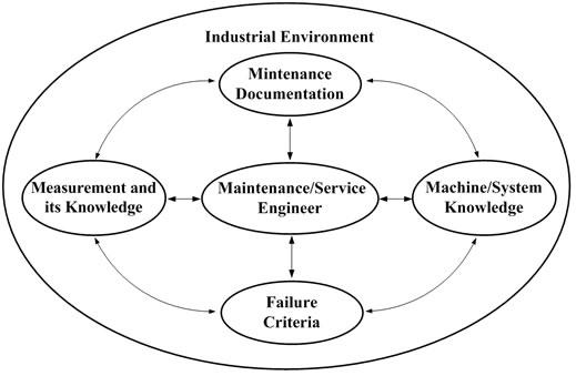
Figure 1. Engineering system of failure analysis in maintenance and service
Value engineering provides a measure of value for the purpose of maintenance and service of semiconductor equipment. Value can be defined as function over cost [6]. The value of maintenance and service for different failure modes needs to be evaluated. The ultimate goal of the maintenance and service support in the fabrication industries is to increase the net value by reducing the cost, and increasing customer’s acceptance during the equipment’s life cycle.
The conversion from customer’s needs to functional requirements in equipment development is an essential issue in a semiconductor business. A systematic method of Quality Function Deployment (QFD) can be applied quantitatively to solve the conversion problem. In realizing QFD, a central element called House of Quality is usually employed. The success of QFD relies on the detailed investigation of the customer’s needs and the evaluation of the markets. The initial tasks in QFD are to acquire market needs by listening to the voice of customer, sorting the needs, and prioritizing the needs numerically. In reliability engineering, the attempt of introducing an integrated usage of QFD and FMEA has been undertaken by several researchers [7].
A machine as a system can be decomposed into many sub-systems for engineering operation and testing. In the
decomposition of semiconductor equipment, it is essential to understand the equipment’s principle and mechanism in operation. The design and implementation of the semiconductor equipment relies on the integration of precision mechanical engineering, electrical control, and system thinking. According to the definition of mechatronics by EEC [8], the technique and the knowledge of semiconductor equipment is classified as a discipline of mechatronics. With the knowledge of mechatronics in semiconductor equipment, failure analysis and maintenance can be undertaken by engineers in service.
Semiconductor equipment is designed and implemented through precision engineering. In the field of precision design, Suh [9] identified two design axioms from abstracting common mapping domains of a body of precision designs, including products, processes, and systems. The foundation of axiomatic design is to construct design mappings in the forward engineering. The design mappings are from Customer Attributes (CAs) to Functional Requirements (FRs), then from FRs to Design Parameters (DPs) and finally from DPs to Process Variables (PVs). Recently, the design method has been integrated with other methods for different applications. For example, a design method to integrate the axiomatic design and robust design was developed for assuring six-sigma quality in product [10]. In addition, some thoughts were proposed on potential integration of axiomatic design with quality tools to enhance product development process [11].
For a semiconductor fabrication process, minimizing the process variations is the fundamental objective in achieving the optimal machine operation. There has long been a desire to increase the yield by utilizing an electrical or mechanical in-process quality control system. Engineers working on designing quality into products and processes should be provided with a tool available for the experimental design in the field tests. Taguchi has developed a robust method for improving the quality of Japanese products with great success [12]. Taguchi’s method is a robust method for improving productivity so that high-quality products can be produced at low cost [13]. The robust method, in essence, is to utilize a Signal-to-Noise (S/N) ratio to estimate and assure the minimum variability in product quality.
Maintenance engineers need to have full knowledge about machine failure in maintenance service. In fabrication industry, a method of FMEA provides a structured approach to analyze the root causes of failure, and assesses the potential failure modes of a process and their causes in risk prevention measures [6,14]. In utilizing FMEA, an integral part is to calculate Risk Priority Number (RPN) for ranking and assessing risk of failure modes [14]. The RPN is used to prioritize items of causes that require additional quality planning or action. The items with the highest RPN and severity ratings usually will be given first consideration. However, the priorities ranking by RPN may not always reflect the true concerns in maintenance management [15].
In the operation of semiconductor equipment, the operational process and equipment setting in production are usually relied on the techniques from R&D and supplier. The operational techniques usually are to be trained through laboratory and field practice.
In the applications of precision engineering to the semiconductor industry, there should also be an efficient and effective maintenance system for providing high performance and quality operations at a reasonable cost. In considering that axiomatic design can be used as the foundation in designing semiconductor equipment, a systematic method through axiomatic design mapping is proposed for engineers to solve the maintenance problems. By integrating the engineering methods mentioned in the previous paragraphs along with the forward and inverse mappings in axiomatic design, a scheme to integrate various methods in maintenance process for machine diagnostics and process optimization of semiconductor equipment is constructed and depicted in Figure 2.
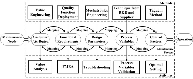
Figure 2. Methods, process, and activities in maintenance and service
In Figure 2, the maintenance needs are initially raised by the customer. In proceeding maintenance process, the value and worth of maintenance will be analyzed and evaluated. The value analysis requires the mapping between the CAs and FRs. The FRs can be deployed and
defined based on the analysis of quality function. By analyzing and evaluating the maintenance needs and FRs, CAs are determined by using the method of value engineering. In proceeding the analysis of FRs in maintenance, FMEA is undertaken to obtain causes and effects of failure modes. For semiconductor equipment, various components are mutually affected regarding the behaviors of machine and its performance. By utilizing mechatronic engineering, the forward mapping from the FRs to DPs is analyzed to give the reverse mapping of DPs that affect the FRs. With the mapping from the FRs to DPs, the DPs which affect FRs can be verified in troubleshooting during maintenance. With the DPs, a mapping from the DPs to PVs for semiconductor equipment can be constructed. The PVs will affect the variations of DPs in equipment during the life cycle of equipment operation. For the PVs, some PVs related to fabrication processes which are sensitive to disturbances will be involved in quality problems. By assuming a set of PVs which may affect the quality specifications, laboratory experiments can be carried out by supplier or through R&D for identifying the key PVs. The key PVs which are defined as Control Factors (CFs) are employed for assuring production quality. In production, an important aspect of quality in setting CFs is to achieve robustness. Since the issue of robustness cannot be addressed until noise factors are given in an environment, designed experiments by Taguchi method are utilized to find out the optimal setting of CFs for minimizing product variance during equipment operation.
2.3 Procedure
Under the diagram constructed in Figure 2, a procedure for realizing maintenance and service will be developed. In the maintenance procedure starting from Maintenance Needs to Operation, there are five activities associated with the mapping domains, respectively. The five activities including Value Analysis, FMEA, Troubleshooting, Process Variables Validation, and Optimal Setting will proceed with the following steps.
1) Value Analysis At first, maintenance needs are initiated by the customer. Therefore, from the initiation of maintenance needs, CAs will be reviewed and revised and the value in CAs will be evaluated iteratively. If the maintenance service is valuable for proceeding the troubleshooting and/or process optimization, the FMEA will be undertaken to analyze the root causes of failure modes.
2) FMEA In proceeding with the FMEA, the failure problem will be defined in operation environment. In addition, information of potential effects of failure and risk factor rating are analyzed and documented. The analysis of failure modes and their causes can be inferred by identifying the failure problem, reviewing FRs, and the corresponding DPs iteratively.
3) Troubleshooting After FMEA, field tests are undertaken for troubleshooting. The failure due to mechanism or system software in semiconductor equipment will be tested first. The troubleshooting is undertaken by iterating test and check in order to resolve any issues of DPs in the subsystems or components.
4) Process Variables Validation If the equipment is functionally correct, the equipment will be controlled and tested by setting PVs in fabrication process software. The operation of equipment will be validated iteratively by reviewing and revising PVs to make sure that PVs are correct and no failures occur in the fabrication process software.
5) Optimal Setting If the equipment operates correctly under the control of fabrication process software, then experimental tests will be applied for process optimization. By analyzing the CFs and noise factors in PVs and testing the CFs in fabrication process software, Taguchi method is applied through reviewing CFs iteratively for obtaining optimal CFs.
The maintenance and service procedure is completed after setting the optimal CFs. The implementation of the maintenance and service procedure will indicate that the failure has been resolved and the machine performance is robust in operation. From the above analysis and referring to Figure 2, a procedure of maintenance and service is proposed and complied as shown in Figure 3.
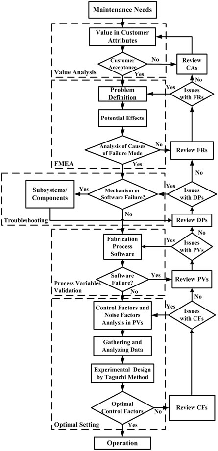
Figure 3. Procedure for maintenance and service
From Figure 3, it is observed that optimal and robust operational quality can be obtained by adjusting CFs as long as there are no issues with PVs. However, if better performance improvement is required, further maintenance service can be undertaken through reviewing PVs, returning PVs to DPs, from DPs to FRs, or even from FRs to CAs for analyzing service value to satisfy customer’s needs.
3. Wire Bonder System
3.1 Mechatronics Structure
The mechatronics functions of subsystems of a wire bonder indicate the functional responsibility by each component in a subsystem. The functionalities of the components of wire bonder equipment can be decomposed into different functional subsystems. For a wire bonder machine K&S (Kulicke and Soffa) Maxμm Plus, the functional subsystems include Console System, Bond Head Assembly, Vision System, Material Handling System, XY-Table Assembly, Equipment Network, and Software. The functional subsystems are composed of different functional components of a mechatronics system. Console System includes sensing components, signal processing and controlling components, and power components. Bond Head Assembly includes driving components, motion executing components, and sensing components. Vision System includes sensing components. Material Handling System includes driving components, motion executing components, and sensing components. XY-Table Assembly includes driving components, motion executing components, and sensing components. Equipment Network and Software includes the network communication components, operating system components and also the application software components. The Equipment Network which is constructed by employing Semiconductor Equipment Communication Standard (SECS), General Equipment Model (GEM), and High Speed Message Series (HSMS) follows the Semiconductor Equipment Materials International (SEMI) standards. From the analysis, a three levels structure diagram is depicted as shown in Figure 4.
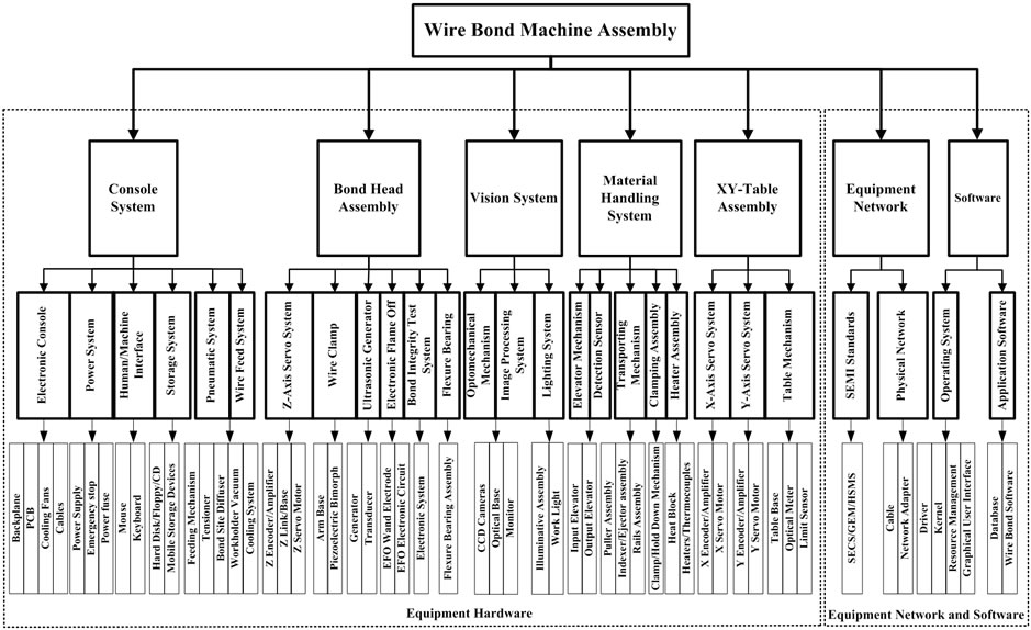
Figure 4. Structure diagram of a wire bonder
The first level is functional subsystems. The second level is components of the corresponding subsystems. The third level is functional elements corresponding to each component. By utilizing the diagram of Figure 4, the mapping of a wire bonder from FRs to DPs
can be analyzed and documented as machine knowledge in Figure 1.
3.2 Knowledge Structure
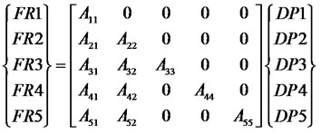
A wire bonder with five modules of subsystem is required to satisfy functional requirements. The mapping between FRs and DPs which satisfies a decoupled module design is given by (1) with weighting Aij as
 (1)
(1)
The FRs in (1) are listed as FR1: Provides command control and electronic control of equipment FR2: Affords bonding motion for each recipe selected FR3: Recognizes the image of materials by operator and machine FR4: Provides material transportation capabilities FR5: Maintains bonding table movement over the working area The DPs for the subsystems in (1) are listed as DP1: Signal, motion, and power control in Console System DP2: Wire bonding is accomplished by mechanisms and controls of Bond Head Assembly DP3: Targeting of devices is accomplished by Vision System DP4: Move the materials for bonding demands as Material Handling System DP5: XY-Table Assembly moves bonding mechanisms over the working space
3.3 Knowledge Representation
The knowledge representation constructed by axiomatic mapping can be derived from decomposition and zigzag mapping [9]. Only two levels in the representation of equipment knowledge are given in the following list. The lower levels of FRs and DPs will be given in the appendix.
1) Console System
FR1-1: All subsystems to be under control DP1-1: Monitor and control system FR1-2: Supply energy resources DP1-2: Power system FR1-3: Control the operation of machine DP1-3: Human/machine interface FR1-4: Software operations and data storage DP1-4: Storage system FR1-5: Air supply and control DP1-5: Pneumatic system FR1-6: Feed wire for automatic bonding DP1-6: Wire feed system
2) Bond Head Assembly
The following components are decomposed to be unique and independent and will be used as the basis for formulating DPs which are corresponding to FRs, respectively. The decomposition is undertaken for the Bond Head Assembly.
2.1 Electronic Flame Off (EFO)
FR2-1: Discharge for wire ball formation DP2-1: EFO assembly 2.2 Wire Clamp
FR2-2: Feed and hold wire DP2-2: Wire clamp assembly 2.3 Ultrasonic Generator (USG)
FR2-3: Generate and transmit ultrasonic energy DP2-3: USG system 2.4 Z-axis Servo System
FR2-4: Bond head positioning and force control DP2-4: Z-axis servo system 2.5 Bond Integrity Test System (BITS)
FR2-5: Detection of bonding outcome DP2-5: Bond integrity test system 2.6 Flexure Bearing Assembly
FR2-6: Provide rotational movement DP2-6: Flexure bearing
3) Vision System
The decomposition is undertaken for the Vision System with DP3 corresponding to FR3.
FR3-1: Clear image FR3-2: Image acquisition with high speed FR3-3: Focus range and field of view extension DP3-1: Illumination and image acquisition system DP3-2: Image processing system DP3-3: Optomechanical extension mechanisms
4) Material Handling System
The decomposition is undertaken for the Material Handling System with DP4 corresponding to FR4.
FR4-1: Carry the materials in the bonding cycle FR4-2: Fix the materials on the bond site FR4-3: Provide the working temperature FR4-4: Prevent materials damaged during transportation FR4-5: Handle magazines during the bonding operation DP4-1: Transporting mechanism DP4-2: Clamping assembly DP4-3: Heater assembly DP4-4: Detection sensor DP4-5: Elevator mechanism
5) XY-Table Assembly
The decomposition is undertaken for the XY-Table Assembly with DP5 corresponding to FR5.
FR5-1: I/O density of IC chip become higher FR5-2: Chip dimension and the bond pad pitch become smaller DP5-1: High speed and steady XY-servo system DP5-2: XY-Table mechanism
4. First Bond Failure and Maintenance
By employing the design mappings combined with Mechatronics Engineering and engineer experience in representing the knowledge of a wire bonder, the failure modes regarding the first bond operation and the effects of various components on performance can be analyzed.
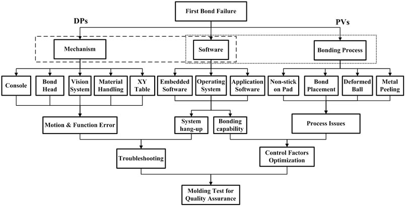
Figure 5. First bond failure analysis
The analysis of the first bond failure through DPs and PVs by the present approach is shown in Figure 5. By utilizing both engineering experience and documented equipment knowledge, the results of wire bonder failure modes corresponding to DPs are analyzed and obtained. In addition to these information and knowledge, the implementation results still rely on experience of measurements, tests, record of FRs, and customer feedback.
4.1 Value Analysis
Value is the first consideration by customers in needing maintenance as shown in Figure 3. In considering the CAs in needing maintenance service, a maintenance task [6] including task description, elapsed time, estimated cost for achieving specified functional performance will be proposed. With the proposed maintenance task analysis, the maintenance value can be justified and managed by customers. By assuming that the proposed service can satisfy CAs, the maintenance on the first bond failure will be undertaken by following Figure 3 through FMEA, Troubleshooting, Process Variables Validation, and Optimal Setting.
4.2 FMEA
In wire bonder industry, the performance of first bond operation can be qualified by employing the tests of ball size, ball shear, intermetallic compound, and etching. For the first bond operation, four common failure modes as Non-stick on Pad, Bond Placement, Deformed Ball, and Metal Peeling are identified as shown in Figure 5.
1) First Bond Failure Modes 1.1 Failure mode Ⅰ: Non-Stick on Pad Ball shear stress calculated with the apparent bonded area will provide a conservative underestimation of the quality of the gold-to-aluminum intermetallic bond line. This failure mode means a bond ball lift out of pad.
1.2 Failure mode Ⅱ: Bond Placement The accuracy of bond position must be controlled for the bond placement under the bond pad size.
1.3. Failure mode Ⅲ: Deformed Ball An ideal bond ball should have the best bond line quality with ball size proper for the bond pad.
1.4. Failure mode Ⅳ: Metal Peeling Bond pad metal peeling is recognized as a serious problem of bonding ability and ball bond reliability in electronic packaging industry.
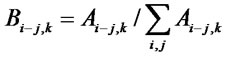
2) RPN Analysis By analyzing the RPN value of the first bond failure, a decision making on the priority in maintenance can be justified and managed. The RPN for four failure modes is evaluated. The RPN is calculated as a mathematical product of the numerical ratings of severity, probability of occurrence, and detection likelihood given by
 (2)
(2)
In (2), the indices i, j, k represent the sub-system, the component of the sub-system, and the failure mode, respectively. The Ai-j,k is the RPN for each DPs of the failure mode k. The sk is a severity rating for failure mode k and the ri-j,k is a severity rating for each DPs of the failure mode k. The mk is a probability rating for failure mode k and the ei-j,k is a probability rating for each DPs of the failure mode k. The nk is a detection rating for failure mode k and the fi-j,k is a detection rating for each DPs of the failure mode k. The RPN is calculated by assigning potential failure modes ranking from 1 to 10 with respect to the severity of the failure mode effect, its probability of occurrence, and the likelihood of its being detected [14, 15]. The assignment of ratings in the present study is according to the classification by SAE J1739 [15]. In applications, these ranking factors are highly dependent on the attributes of the system in operation. For providing a direct comparison of failure effects, the RPN value is normalized to give
 (3)
(3)
The results of RPN ratio for the four kinds of failure modes of the first bond process are to be computed by utilizing (2) and (3) with data from Table 1.The results of RPN ratio with respect to DPs for the four failure modes are calculated and obtained as shown in Figure 6. From Figure 6, the optimal decision and associated actions can be inferred. In Figure 6, DPs with higher RPN
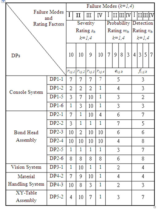
Table 1. Rating factors for evaluation of RPN in the first bond failure modes
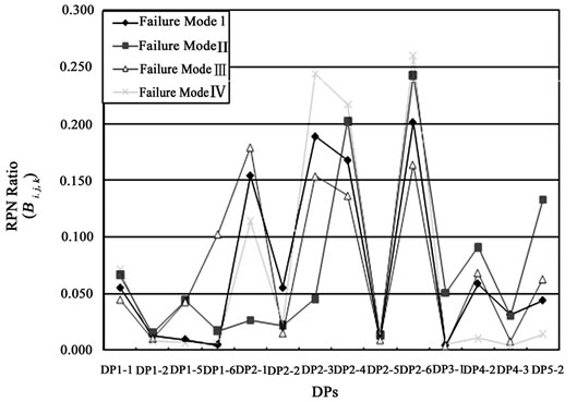
Figure 6. RPN ratio of maintenance for first bond process
ratio for each failure mode are assumed to be more important and given higher maintenance priority than those having a lower RPN ratio. From Figure 6, it is observed that the highest priority for failure mode Ⅰ, Ⅱ, and Ⅳ is DP2-6. The DP2-6 is a flexure bearing. For failure mode Ⅲ, the highest priority is DP2-1. The DP2-1 is an EFO assembly. The priority distribution of RPN ratio for the components of wire bonder provides enough information for maintenance engineers to realize the effects of failure modes.
4.3 Troubleshooting
If there is no failure in the Software of Figure 5, the causes for the failure of DPs in the mechanism of the wire bonder are obtained by utilizing the knowledge representation and engineering experience in Figure 5 to give the following list.
1) Console System: failure related to mode Ⅰ, Ⅱ, and Ⅲ
DP1-1: Monitor and control system DP1-2: Power system DP1-5: Pneumatic system DP1-6: Wire feed system
2) Bond Head Assembly: failure related to mode Ⅰ, Ⅱ, Ⅲ, and Ⅳ
DP2-1: EFO assembly DP2-2: Wire clamp assembly DP2-3: USG system DP2-4: Z-axis servo system DP2-5: Bond integrity test system DP2-6: Flexure bearing
3) Vision System: failure related to mode Ⅱ
DP3-1: Illumination and image acquisition system
4) Material Handling System: failure related to mode Ⅰ, Ⅱ, and Ⅲ
DP4-2: Clamping assembly DP4-3: Heater assembly
5) XY-Table Assembly: failure related to mode Ⅱ and Ⅲ
DP5-2: XY-Table mechanism From the analysis of DPs in the knowledge representation, causes analysis, and utilizing engineering experience for the first bond failure, the detail troubleshooting result of DPs is obtained as shown in Figure 7. The lower levels of DPs in Figure 7 are referred to Appendix. In Figure 7, the DPs are employed as DP1 for Console System, DP2 for Bond Head Assembly, DP3 for Vision System, DP4 for Material Handling System, and DP5 for XY-Table Assembly.
4.4 Process Variables Validation
From Figure 7, the related PVs will be analyzed through the mapping from DPs to PVs [9]. The PVs related to the bonding process in the maintenance and service of equipment operation can be analyzed, inferred, tested, and verified. For the first bond process, the environment
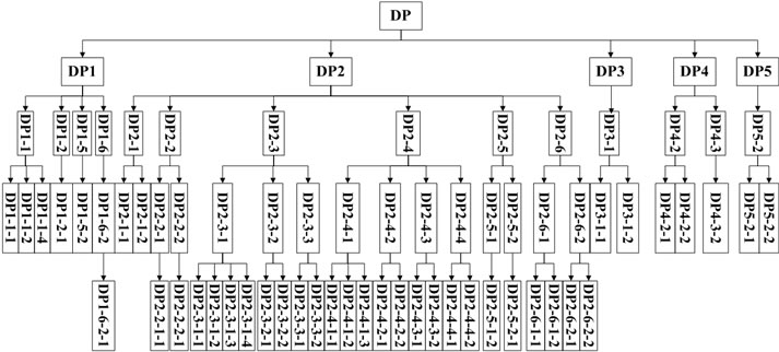
Figure 7. First bond failure troubleshooting
is met by the production standard. Bonding material and bonding temperature are fixed. A gold wire of 20μm is used. The temperature of bond-site area is 150℃. Suitable capillary is chosen on K&S Maxμm Plus wire bonder. From the results obtained for the process study, the feedback of quality analysis responds the relationships between PVs and DPs. The PVs related to the process of the first bond failure are validated to give PV1-1: Signal to electronic devices PV1-2: Different rating of supply voltages PV1-3: Different input commands PV1-4: Different program storage selections PV1-5: System flow rate adjustments PV1-6: Wire feed flow rate adjustments PV2-1: Adjustment of EFO firing time and control current PV2-2: Adjust wire pullout PV2-3: Setting ultrasonic power utilization PV2-3-1: Setting USG applied amplitude and frequency PV2-3-2: Capillary tube and transducer installation adjustment PV2-3-3: Setting USG in bonding process PV2-3-3-1: Setting pre-bleed USG PV2-3-3-2: Setting bonding USG PV2-4: Variables in Z-axis motion on bonding time and force PV2-4-1: Bonding force PV2-4-2: Z-axis position PV2-4-3: Bonding time PV2-4-4: Capillary searching speed PV2-5: Signal of bonding processes PV3-1: Adjust optical limit and select image setting PV3-2: Set parameters of image processing PV3-3: Select different cameras and magnifications PV4-1: Material transportation variables PV4-2: Clamping compensation adjustments PV4-3: Variables of bonding temperature PV4-4: Set up sensor sensitivity PV4-5: Adjust elevator parameters PV5-1: Adjust XY-axes motion and speed PV5-2: Adjust XY-motion accuracy
4.5 Optimal Setting
Minimization of the variation of the bonding process is to achieve high yield in production. The specifications of bond ball can be set according to customer’s requirements. Optimization of CFs for assuring bond ball quality is undertaken by employing Taguchi method [12,13]. In the Taguchi’s experimental tests, the quality target is called signal and the variation in the target is called noise.
1) Quality Characteristics
For the first bond process, the quality requirements of ball size and ball shear are specified. The quality target of ball size, as tri-axial appearances, is given as Nominal-the-Best. The quality target of ball shear force is given as The-Larger-the-Better. The shear force is obtained by utilizing shear strength, as shear force per unit area, multiplied by the estimated area. The quality specifications for the first bond in the experiment are given as
1.1. Quality Targets:
a. Ball size: Nominal-the-Best Ball X & Ball Y (Plane of bond pad)-40μm +/-2μm Ball Z (Plane orthogonal to bond pad)-10μm +/-2μm b. Ball shear: The-Larger-the-Better Ball shear force-Above 12 grams 1.2. Portability of Quality:
For the requirement of portability of quality, experimental tests need large sample size, different machine bonding, and high productive yield.
2) Control Factors Analysis
The function of a wire bonder is assumed correct. The CFs influencing the quality of bond ball forming are selected. For the first bond, the experimental CFs use Constant Velocity in Capillary Searching Speed (PV2-4-4), Bonding USG (PV2-3-3-2), Bonding Time (PV2-4-3), Bonding Force (PV2-4-1), and Pre-Bleed USG (PV2- 3-3-1) to verify failure modes Ⅰand Ⅲ.
3) Experimental Tests and Confirmation
The experimental tests are undertaken in laboratory by the combination of five CFs and different levels as shown in Table 2.

Table 2. Control factors and levels for first bond process.
For portability tests, three devices are separately bonded on two machines. For one factor with two levels and four factors with three levels in combination, the experimental results are based on L18 orthogonal arrays and listed in Table 3.
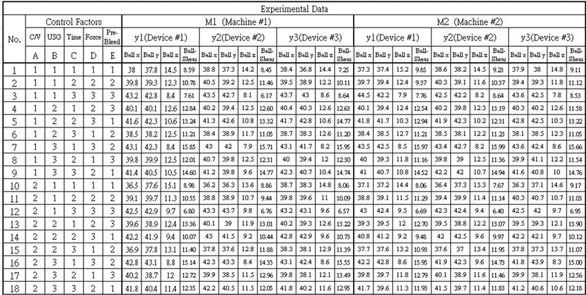
Table 3. Experimental orthogonal arrays and experimental data (K & S Maxμm Plus Wire Bonder)
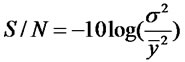
By following the procedure of Taguchi method [13], the tables and graphs of factor response are obtained and employed to show S/N ratio for different combinations of parameters. The S/N ratio for the Nominal-the-Best is calculated by (4) with the mean and standard deviation of data yi, as
 (4)
(4)
The S/N ratio for The-Larger-the-Better is calculated by (5) as
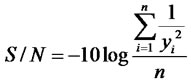 (5)
(5)
From Figure 8, it is observed that the variations of bonding time for the quality targets are small. Thus, the bonding time is considered as an adjustable factor and selected as C1. From the S/N ratio obtained in Figure 8, the final optimal combinations are inferred by four sets of parameters in sequence as [A1 B2 C1 D2 E2], [A1 B3 C1 D2 E2], [A1 B2 C1 D2 E3], [A1 B3 C1 D2 E3]. Al
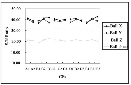
Figure 8. Overall factors response
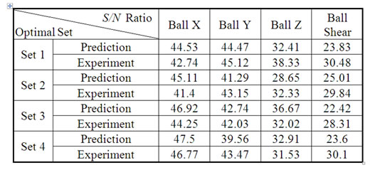
Table 4. Comparisons of S/N ratio for four sets of optimal combination
though there are four sets of optimal parameters in solution, a set of optimal parameters will be selected by confirmation experiments. The confirmation test is undertaken by the fabrication of ten devices under four sets of optimal combinations respectively. Four sets of confirmation for the experimental and predicted S/N are obtained as given in Table 4. In Table 4, the experimental result is calculated from the mean S/N ratio of testing results and the prediction of S/N ratio is obtained by utilizing a linear additive predictive model. The confirmation test reveals that the quality targets are satisfied by all the four sets of optimal combination. By comparing the
closeness of S/N ratio of each set of prediction and experimental result in Table 4, it is realized that the interactions of CFs are insensitive for Ball X and Ball Y, but the interactions for Ball Z and Ball Shear are sensitive.
With the interactions in laboratory tests, the optimal result obtained cannot be directly applied for customer service. In order to achieve optimal bonding performance and robustness in field operation, further experimental designs and tests are required [13]. For the present results obtained in laboratory, the results of ball size are acceptable by the quality target. The experimental S/N ratio of Ball Shear for Set 1 is higher than the other three sets of experimental results. With the higher S/N ratio in Set 1, the wire bonding process will be more robust. From the experimental confirmation tests, the final optimal parameters for K&S Maxμm Plus are [A1 B2 C1 D2 E2], i.e. Capillary Searching Speed: 0.1 mil/ms, Bonding USG: 90 mAmp, Bonding Time: 8 ms, Bonding Force: 25 grams, and Pre-bleed USG: 45 %.
5. Conclusions
A systematic framework which consists of a system of equipment failure analysis, methods, process, and activities, and a procedure is proposed for the maintenance and service of semiconductor equipment. The maintenance procedure in sequence starting from Maintenance Needs, Value Analysis, FMEA, Troubleshooting, Manufacturing Process Validation, and Optimal Setting to Operation is developed. By employing axiomatic design mapping integrated with Value Engineering, Quality Function Deployment, Mechatronics Engineering, Techniques from R&D and Supplier, and Taguchi Method, the framework is highly effective in translating Maintenance Needs into Design Parameters for troubleshooting, and into Control Factors for process optimization. In the troubleshooting and process optimization of a wire bonder, the framework is applied to assure robust production quality in the first bond process by K&S Maxμm Plus. The systematic framework provides an effective and efficient scheme to provide maintenance and service for the acceptance or worth by customers.
Appendix
The lower levels of FRs and DPs are listed as follows.
1) Console System
FR1-1-1: Mechanism motion control FR1-1-2: Signal transmission FR1-1-3: Image processing FR1-1-4: Communication relationship DP1-1-1: Electronic mechanism control DP1-1-2: Sensor interfaces DP1-1-3: Image processing system DP1-1-4: Circuit connection and cabling FR1-2-1: Provide power for all components FR1-2-2: Circuit and mechanism protection DP1-2-1: Power supply assembly DP1-2-2: Electronic fuse and emergency stop FR1-3-1: Motion movement, including function and message selections in the GUI FR1-3-2: Command typing and entry of data DP1-3-1: Mouse device DP1-3-2: Keyboard FR1-4-1: Bonder software and applications FR1-4-2: Portable bond programs and applications DP1-4-1: Hard disk DP1-4-2: Mobile storage device (Floppy, USB storage device, CD ROM, etc.)
FR1-5-1: Mechanism protection FR1-5-2: Fabrication process demand FR1-5-3: Auxiliary machinery DP1-5-1: Cooling air DP1-5-2: Vacuum system and compressed air DP1-5-3: Air pressure with mechanisms FR1-6-1: Precise wire feed for bonding continuously FR1-6-1-1: Control wire feed motion and timing FR1-6-1-2: Feed wire automatically FR1-6-2: Optimal bonding quality FR1-6-2-1: Maintain the bond ball quality FR1-6-2-2: Looping performance DP1-6-1: Feeding mechanism DP1-6-1-1: Motorized spool assembly with sensor detection DP1-6-1-2: Air guide and wire detect sensor DP1-6-2: Optimal wire feed path in pneumatic system DP1-6-2-1: Tension the wire and hold the ball in the center of capillary DP1-6-2-2: Optimizing air guide to reduce wire whipping
2) Bond Head Assembly
FR2-1-1: Required wire bonding quality by EFO FR2-1-1-1: Fine Pitch bonding FR2-1-1-2: High yield and bond ability DP2-1-1: Three-phase controller of EFO.
DP2-1-1-1: Control of discharge energy of the EFO DP2-1-1-2: Control the wear and lifetime of electrode FR2-2-1: Proven reliability in operation FR2-2-1-1: Eliminate motion wear FR2-2-1-2: High operational times FR2-2-2: Clamp performance FR2-2-2-1: Active damping of clamping mechanical resonance FR2-2-2-2: Shorter opening and closing time DP2-2-1: Wire contact in handling and mounting DP2-2-1-1: Compliant motion mechanism DP2-2-1-2: Fixed arm and bimorph arm DP2-2-2: Wire clamp driver with voltage profiling for open-loop control DP2-2-2-1: Bimorph clamp actuator DP2-2-2-2: Piezoelectric actuation FR2-3-1: Efficient and effective ultrasonic energy FR2-3-1-1: Ball roundness FR2-3-1-2: Fine pitch wire bonding capabilities FR2-3-1-3: High speed wire bonding FR2-3-1-4: Minimize the loss of ultrasonic energy FR2-3-2: Good placement accuracy FR2-3-2-1: Higher bonding accuracy FR2-3-2-2: Good stability and reproducibility of capillary tip motion FR2-3-3: Good bonding capability FR2-3-3-1: USG applied before capillary contact substrate FR2-3-3-2: USG applied during contact and bonding operation DP2-3-1: Generation, transmission and focusing mechanism of ultrasonic energy DP2-3-1-1: Accurate ultrasonic amplitude and frequency DP2-3-1-2: High frequency vibration of PZT DP2-3-1-3: Increase system stiffness by using titanium DP2-3-1-4: Holder and horn mechanism DP2-3-2: Vibration of transducer tip DP2-3-2-1: Transducer material and structure DP2-3-2-2: Capillary clamping system of the transducer DP2-3-3: Ultrasonic energy by USG in bonding process DP2-3-3-1: Capillary tube and ultrasonic profile DP2-3-3-2: Bonding ultrasonic control circuitry FR2-4-1: Precise motion and force control on bond head FR2-4-1-1: Capable of high acceleration FR2-4-1-2: High motion repeatability FR2-4-1-3: Bonding accuracy FR2-4-2: Monitor Z-axis position for force control FR2-4-2-1: Monitor bonding tool position precisely FR2-4-2-2: Real-time signals response FR2-4-3: Speed control of bond head FR2-4-3-1: Higher acceleration FR2-4-3-2: High performance of control system FR2-4-4: Capillary and wire motion control FR2-4-4-1: Detecting and switching the approaching to substrate FR2-4-4-2: Searching speed requirement DP2-4-1: Voice coil actuating control system DP2-4-1-1: Minimize the mass of the motor and balance the centre of gravity of the rotational inertia.
DP2-4-1-2: Electromagnetic and mechanical subsystems DP2-4-1-3: Accurate servo mechanism DP2-4-2: Encoder assembly DP2-4-2-1: High resolution optical grid DP2-4-2-2: Electronic encoder system DP2-4-3: Speed control system DP2-4-3-1: Low inertia mechanism DP2-4-3-2: High bandwidth in control loop DP2-4-4: Capillary and wire motion control system DP2-4-4-1: Detection and switching control mechanism DP2-4-4-2: Searching speed control circuitry FR2-5-1: Capable of detection FR2-5-1-1: Enhance detection signal FR2-5-1-2: Avoid false detection FR2-5-2: Test for the outcome of the bonding process FR2-5-2-1: Detect non-stick on pad FR2-5-2-2: Detect non-stick on lead FR2-5-2-3: Detect the tail left on the capillary after wire-cycle bonding FR2-5-2-4: Detect ball formation by electronic firing DP2-5-1: Effective detector DP2-5-1-1: High-impedance devices DP2-5-1-2: Noise eliminator DP2-5-2: Electrically detectable interface system DP2-5-2-1: Current from bond pad to machine chassis ground DP2-5-2-2: Current from lead to machine chassis ground DP2-5-2-3: Current from wire tail to machine chassis ground DP2-5-2-4: Current from wire tail to wand FR2-6-1: Support precision machine components with rotational motion FR2-6-1-1: Robust bearing FR2-6-1-2: Infinite lifetime/service time FR2-6-2: Provide motion accuracy of bond head FR2-6-2-1: Minimize the restoring force FR2-6-2-2: Increase bonding speed and line pitches DP2-6-1: Robust linkage with flexure pivot DP2-6-1-1: Stainless steel cross-flexure pivot bearings DP2-6-1-2: Zero wear and friction operation DP2-6-2: Bond head inertia and stiffness in assembly DP2-6-2-1: Flexure bearing pivots in loading angle DP2-6-2-2: High stiffness in assembly
3) Vision system
FR3-1-1: Sufficient illumination FR3-1-2: Clear image features FR3-2-1: High accuracy and robustness FR3-2-2: Faster image processing FR3-3-1: Show bond height difference and capture wider image of bonds FR3-3-2: Image features requirements DP3-1-1: Illumination assembly and work light DP3-1-2: Image acquisition system DP3-2-1: Pattern matching by image processing tools DP3-2-2: High-speed processor DP3-3-1: Mechanism for different magnifications DP3-3-2: Installation and calibration
4) Material Handling System
FR4-1-1: Pull the materials from input magazine into work holder FR4-1-2: Support the materials with suitable rail width FR4-1-3: Index the materials into bond site and index motion FR4-1-4: Eject the materials into output magazine FR4-2-1: Mechanism secures the carrier during bonding operation FR4-2-2: Hold the fine-pitch and specific materials bonding more stable FR4-3-1: Raise temperature before entering the bond site FR4-3-2: Maintain the bonding temperature FR4-3-3: Prevent damage to devices after bonding by rapid heating and cooling FR4-4: Prevent materials damaged during transportation FR4-4-1: Prevent devices damaged during transportation from input magazine or into output magazine FR4-4-2: Prevent devices damaged during injection FR4-4-3: Prevent devices damaged during ejection FR4-5-1: Inject/eject the magazine FR4-5-2: Jog/reverse magazine DP4-1-1: Injector assembly DP4-1-2: Front and real rails assembly DP4-1-3: Indexer assembly DP4-1-4: Ejector assembly DP4-2-1: Clamp mechanism DP4-2-2: Hold down mechanism DP4-3-1: Pre-heat plate DP4-3-2: Bond-site heat plate DP4-3-3: Post-heat plates DP4-4-1: Wall sensors on both sides of input and output DP4-4-2: Inject Y-axis sensor detection DP4-4-3: Jam detection sensor during ejection DP4-5-1: Gripper motor injects and ejects magazines DP4-5-2: Z-axis motor drives the jog/reverse motion
5) XY-Table Mechanism
FR5-1-2: Less structural vibration FR5-2-1: High motion precision FR5-2-2: High precision in fabrication DP5-1-1: High acceleration DP5-1-2: High damping in material and servo loop DP5-2-1: Decrease joint clearance DP5-2-2: Decrease the wear of motion joint
REFERENCES
- G. G. Harman, “Wire bonding in microelectronics, material, processes, reliability, and yield,” 2nd edition, McGraw Hill, New York, 1997.
- C. Boit, R. Weiland, A. Olbrich, U. Muehle, and B. Simmnacher, “Failure analysis concepts for microelectronics
- technologies and manufacturing of the future,” Proceedings of SPIE, Vol. 4406, pp. 1–12, 2001.
- D. T. Rooney, D. Nager, D. Geiger, and D. Shanguan, “Evaluation of wire bonding performance, process conditions, and metallurgical integrity of chip on board wire bonds,” Microelectronics Reliability, Vol. 45, No. 2, pp. 379–390, 2005.
- A. Garg and S. G. Deshmukh, “Maintenance management: Literature review and directions,” Journal of Quality Maintenance Engineerings, Vol. 12, No. 3, pp. 205–238, 2006.
- M. Murray, K. Fletcher, J. Kennedy, P. Kohler, J. Chambers, and T. Ledwidge, “Capability assurance: A generic model of maintenance,” ICOMS-96, Maintenance Engineerings Society of Australia Capability Assurance, paper 72, 1996.
- B. S. Blanchard, “System engineering management,” John Wiley & Sons, New York, 1991.
- M. Braglia, G. Fantoni, and M. Frosolini, “The house of reliability,” International Journal of Quality and Reliability Management, Vol. 24, No. 4, pp. 420–440, 2007.
- D. A. Bradley, D. Dawson, N. C. Burd, and A. J. Loader, “Mechatronics: Electronics in products and processes,” Chapman & Hall, London, 1993.
- N. P. Suh, “Axiomatic design: Advances and applications,” Oxford Press, New York, 2001.
- B. S. El-Haik, “Axiomatic quality: Integrating axiomatic design with six-sigma, reliability, and quality Enginee ring,” John Wiley & Sons, New York, 2005.
- H. A. Mohsen and E. Cekecek, “Thoughts on the use of axiomatic designs within the product development process,” Proceedings of 1st International Conference of Axiomatic Design, Cambridge, Massachusetts, USA, 2000.
- G. Taguchi, “Taguchi methods: Signal-to-noise ratio for quality evaluation,” Michigan: American Suppliers Institute Press, Vol. 3, 1991.
- M. S. Phadke, “Quality engineering using robust design,” Prentice Hall, London, 1989.
- R. Whitcomb and M. Rioux, “Failure modes and effects analysis (FMEA) system deployment in a semiconductor manufacturing environment,” Proceedings IEEE/SEMI Advanced Semiconductor Manufacturing Conference Works, pp. 136–139, 1994.
- J. B. Bowles, “An assessment of RPN prioritization in a failure modes effects and criticality analysis,” Proceedings Annual Reliability and Maintainability Symposium, pp. 380–386, 2003.