Engineering
Vol.6 No.4(2014), Article ID:43803,8 pages DOI:10.4236/eng.2014.64021
Ultrasonic Technology for Enhanced Oil Recovery
Anna Abramova1*, Vladimir Abramov1, Vadim Bayazitov1, Artyom Gerasin2, Dmitriy Pashin3
1Kurnakov Institute of General and Inorganic Chemistry of the Russian Academy of Sciences, Russia, Moscow
2CUT-Service Ltd., Russia, Moscow
3Centre of Nanotechnologies of the Republic of Tatarstan, Russia, Kazan
Email: *anna_v_abramova@mail.ru
Copyright © 2014 by authors and Scientific Research Publishing Inc.
This work is licensed under the Creative Commons Attribution International License (CC BY).
http://creativecommons.org/licenses/by/4.0/


Received 23 December 2013; revised 23 January 2014; accepted 2 February 2014
ABSTRACT
An ultrasonic technology for enhanced oil recovery is described. For the implementation of this technology, the equipment was specially developed, taking into account the working conditions. The criteria for selections of well candidates were developed. The technology has been tested in two different regions in different geological conditions. The results of these field tests indicate the high efficiency of the proposed technology. The success rate of the method reached 90% and the increase in oil production was in the range of 40% - 100%.
Keywords:Ultrasound; Enhanced Oil Recovery; Oil Well Treatment

1. Introduction
The efficiency of oil recovery is not satisfied at the moment (the oil recovery is less than 40%). Existing technologies of enhanced oil recovery (EOR) are energy-intensive, labor-intensive and not environmentally safe. Thus, the development of new technologies and modification of traditional ones (including those based on physical influence) are urgent tasks.
The most frequently used and effective method of physical EOR is hydrofracturing (its market share among physical EOR reaches 60%). This method uses the energy of pressure in the reservoir and increases the oil production by 2 - 3 times, which corresponds to 5 - 7 tons production increase per day in Western Siberia and reaches 23 tons/day in the Samara region. Such operation requires the use of 4 - 8 heavy units near the well, as well as special wellhead equipment and packers. Significant loads on the equipment lead to the necessity of regular maintenance, after 4 - 5 operations capital repair works are required. All this makes the operation very costly.
Other physical EORs, which are currently used are electromagnetic treatment and wave treatment. These methods involve the use of various physical fields instead of matter to affect the reservoir. Such technologies are more costly and energy effective compared to hydro fracturing. According to [1] -[3] , the acoustical method of EOR (including ultrasonic EOR) is one of the most promising wave methods. The effect of ultrasound on the well and the reservoir which leads to enhanced production, is based on two aspects of sonication that are relevant (1) enhancement of the flow of oil through the rocks into the pumping pool and (1) reduction of the viscosity of the oil that would make it easier to pump. The efficiency of this method can be significantly increased if effective equipment will be developed, the wells-candidates will be chosen right and mathematical modeling of the process will be carried out prior to the treatment and during it.
One of the organizations, specialized in development of wave methods of EOR is Viatech Ltd. [4] -[6] . The modified acoustical method of EOR, based on the mentioned above principles, and ultrasonic equipment for its implementation developed by us for Viatech was successfully tested on the Samotlor oil field by the specialists of CUT-Service Ltd. before [7] [8] . In this article, a description of developed equipment for ultrasonic enhanced oil recovery is given, the discovered criteria for well selection and field test results of the developed technology in the Samara region and in Western Siberia are reported.
2. The Developed Ultrasonic Equipment
The equipment developed by us for Viatech Ltd. for the implementation of the modified acoustical technology consists of ground and downhole equipment.
The ground equipment includes an upgraded ultrasonic generator TS10W with the power of 10 kW. Its block diagram is shown in Figure 1. The generator consists of the following basic units: the power supply unit, the power unit, the magnetizing unit and the control unit. Unlike generators of the previous generations the controller of this modification includes a unit for processing the information about the pressure and temperature in the borehole, which is sent from the downhole tool. It is necessary to perform processing of this data in order to choose the treatment modes correctly and adjust them during operation. After processing the data is sent to an external computer.

Figure 1. Block diagram of the generator TS10W.
The downhole equipment includes a sonotrode PSMS-42 (with the diameter 42 mm) and a registrator of geophysical data (temperature, pressure, flow). The ultrasonic tool has the form of a cylinder. It converts longitudal oscillation into radial, which affect the wellbore perforation zone.
The geometrical dimensions of the waveguide system are calculated in such a way that the natural frequency of the system as close as possible to the frequency of the electro-acoustic transducer. The efficiency of the process is strongly dependent on the correct modeling of the oscillations.
The finite element method, which was widely used in the last decade [9] , was used for modeling (the ANSYS Software was used). The oscillation form of the “push-pull” type sonotrode PSMS-42 is shown in Figure 2. Calculations show that the maximum amplitude is generated in the center of the waveguide system. In order to make the construction stable radial oscillation nodes are located near the connection with the transducers.
To select the optimal design of the tool various waveguide systems were designed, modeled, manufactured and tested. The final decision on the form of the waveguide was made based on the results of experiments performed by us on the experimental setup shown in Figure 3. The evaluation of the effectiveness of the various waveguide systems was based on the measurement of the amplitude of the side wall of the chamber generated by the waveguide system at the same power supply and the effect on the core sample in the chamber.
Thus based on the calculations and experiments the downhole tool on the basis of magnetostrictive transducers PSMS-42 was developed. This tool was designed in such a way that its frequency fit into the frequency range 13 to 26 kHz, which is determined by the generator. The acoustic radiation power is 2 - 3 kW (depending on the cable length and power supplied).
The technical characteristics of the tool are given in Table 1.
As it was shown in [10] , the criteria, listed in Table 2 should be taken into account when choosing the wells for ultrasonic treatment. The wells for ultrasonic treatment were chosen based on these criteria.


Figure 2. Oscillation form of a “push-pull” type sonotrode with a smooth surface.
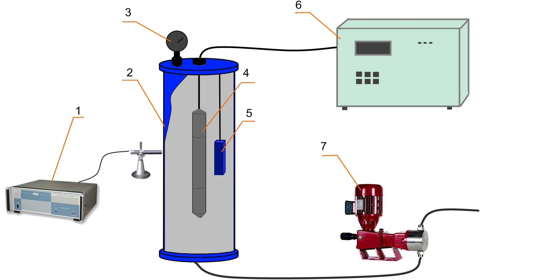
Figure 3. Experimental equipment for testing of downhole tools: 1: device for the measurement of the amplitude of the camera walls oscillations (Vibrometer SVAN 912M); 2: high pressure chamber; 3: manometer for measurement of the pressure in the chamber; 4: waveguide system with magnetostrictive transducer; 5: sealed capsule with a core sample; 6: ultrasonic generator TS10W, 7: pump.

Table 1. Technical characteristics of the tool PSMS-42.
Table 2. The criteria for selection of candidate wells for sonochemical treatment.
3. Special Machinery, Equipment and Methodology of Field Test Operations of the Ultrasonic Treatment
In order to develop the optimal methodology of field test operations a number of tests have been carried out on the Samotlor field. The following methodologies have been tested: ultrasonic treatment with depression before and after it, created by swabbing without packers; ultrasonic treatment with depression before and after it, created by swabbing with packers; ultrasonic treatment with depression before and after it, created by a nitrogen unit without packers; ultrasonic treatment with depression before and after it, created by a nitrogen unit with packers; ultrasonic treatment with depression before and after it, created by a booster installation; ultrasonic treatment with depression before and after it, created by a jet pump. It was revealed that the highest increase in production is achieved when ultrasonic treatment with depression before and after it, created by a jet pump is used. Thus, the following the following machinery, equipment and methodology of the field test operations were used during the field tests:
Equipment:
• Self propelled wire line truck (type ПКС-5);
• Pump unit (type СИН-32);
• Vehicle АЦ-10 with technical water;
• Ultrasonic equipment described above;
• Geophysical downhole tool “Sova”;
• Registrator of the geophysical parameters (type “Yugra”).
Methodology (preparation):
1) Capping of the well, decent of the processing tubing, installation of the packer (at a distance of no more than 1 meter above the zone of perforation).
2) The wire line truck and the pump unit are grounded and connected to the source of electrical power of the well pad.
3) The ultrasonic equipment is transferred from the transport position to the working position.
Methodology (treatment):
1) The geophysical downhole tool “Sova” is connected through a special adapter to the cable and lowered to the perforation zone. Geophysical parameters are investigated, in particular flow profile, pressure, temperature. Then the tool is removed from the well and disconnected.
2) The ultrasonic tool is put into the lubricator and connected to the cable.
3) The ultrasonic downhole tool is lowered into the well through the tubing (Figure 4).
4) Ultrasonic treatment of the wellbore perforation zone is carried out (the program is made up based on the geophysical parameters for each well individually).
5) During the treatment the changes of the parameters are monitored, the treatment program is adjusted.
6) After short term treatment of wells with light oil depression is created into the well using the pumping unit, the colmatants disconnected by the ultrasonic waves are removed from the well.
7) Then the equipment is removed and disassembled.
8) The pump unit is disconnected.
4. Results of the Field Tests and Discussion
As described above the round trip operation technology for PSMS-42 is almost similar to the one used during geophysical studies of the well [6] . In our case, the downhole tool PSMS-42 with the electro acoustic transducers and sonotrodes is lowered into the wellbore perforation zone through the tubing on a cable with the length of 4000 m.
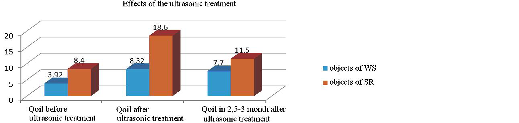
In Western Siberia (WS) and the Samara Region (SR) more than 100 ultrasonic operations were performed in the period from 2010 to 2013. An average increase in oil production after the operation of 4.4 tons/day for WS and 10.2 tons/day for the SR was achieved. Figure 5(a) shows a diagram of the oil production before and after ultrasonic treatment, and Figure 5(b) illustrates the changes in the basic parameters of the well in 3 months after an ultrasonic treatment.
As ultrasonic treatment is done during capital workover of the well, it is often accompanied by optimization of the pumping equipment. Often the changes in oil production after a workover with ultrasonic treatment are by mistake explained by this optimization. Thence we have done an analysis and evaluated the effect after ultrasonic

Figure 4. Hardware elements arrangement during ultrasonic treatment: 1) oil reservoir; 2) ultrasonic downhole equipment; 3) packer; 4) tubing; 5) casing valve; 6) lubricator; 7) flowout line; 8) cable feed; 9) cable; 10) wire line truck ПКС-5; 11) pump unit СИН-32, 12-house.
 (a)
(a)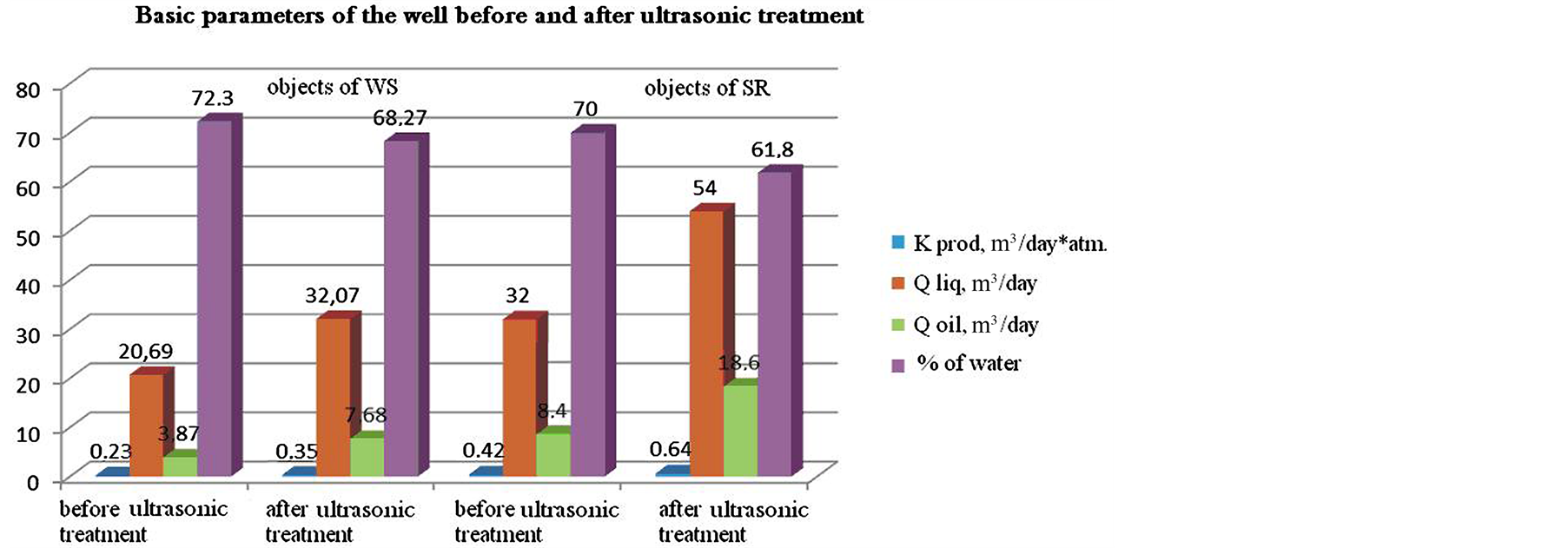 (b)
(b)
Figure 5. Effect of the ultrasonic treatment: (a) On the oil production; (b) On other parameters of the well after the treatment.
 (a)
(a) (b)
(b)
Figure 6. Average changes of the production coefficient (а) and water cut (b) of wells after ultrasonic treatment and optimization of pumping equipment.
treatment by comparing the changes in the productivity factor and water cut of wells after ultrasonic treatment with the changes of the same factors after optimization of the pumping equipment without the ultrasonic treatment (two sets of 30 vertical wells were considered). The first set was compiled from wells where ultrasonic treatment and optimization of the pumping equipment was carried out. On the second set of wells, only the optimization was carried out.
As it is shown in Figure 6(a), ultrasonic treatment leads to an increase of the productivity factor of oil wells by 33% in average. In addition, the selective treatment of the formation layers leads to a decrease of the water cut of the well by 4% in average (Figure 6(b)). In well where only the optimization of pumping equipment was carried out without ultrasonic treatment, a drop of the productivity factor of 5.6% and an increase in the water cut of 1.5% was observed.
The additional production of oil after ultrasonic treatment was monitored in WS during 18 months. Based on this monitoring the numbers, shown in Figure 7 were calculated.
 (a)
(a) (b)
(b)
Figure 7. (a) Changes of the oil (black, tons/day) and fluid (blue, m3/day) production; (b) Changes of the production coefficient of wells treated using the ultrasonic EOR technology.
5. Conclusion
Thus, the results of field tests of the ultrasonic EOR technology in Western Siberia and the Samara region under different geophysical conditions indicate the high efficiency of the proposed technology. Based on the monitoring of more than 100 wells after ultrasonic treatment in two different regions, the following conclusion can be drawn: The success rate of the method reaches 90% and the increase in oil production is in the range of 40% - 100%. The main advantages of the ultrasonic EOR technology are low energy consumption, the possibility to treat the reservoir selective, no harm to the well and its casing, no harm to the environment and to people.
References
- Dyblenko, V.P., Kamalov, R.N., Sharifullin, R.J. and Tufanov, I.A. (2000) Increase of the Productivity of Wells Using Vibro Wave Treatment. Nedra, Moscow.
- Kuznetsov, O.L. and Efimova, S.A. (1983) The Use of Ultrasound in the Oil Industry. Nedra, Moscow.
- Kuznetsov, O.L., Simkin, E.M. and Chillingar, J. (2001) Physical Principles of Vibrational and Acoustic Treatment of Oil and Gas Reservoirs. Mir, Moscow.
- Mullakaev, M.S., Abramov, V.O. and Pechkov, A.A. (2009) Ultrasound Equipment for Productivity Restoration of Oil Wells. Chemical and Petroleum Engineering, No. 3, 12-17.
- Mullakaev, M.S., Abramov, O.V., Abramov, V.O. and Pechkov, A.A. (2009) Ultrasonic Technology for Restoration of the Productivity of Oil Wells. Chemical and Petroleum Engineering, No. 4, 19-23.
- Mullakaev, M.S., Abramov, V.O., Pechkov, A.A., Eremenko, I.L., Novotorzev, V.M., Bayazitov, V.M., Esipov, I.B., Baranov, D.A. and Saltikov, A.A. (2012) Ultrasonic Technology for the Increase of the Productivity of Wells with Low Production. Petrolium Engineering, No. 4, 25-31.
- Abramov, V.O., Mullakaev, M.S., Kalinnikov, V.T., Abramova, A.V., Bayazitov, V.M., Esipov, I.B., Saltikov, A.A. and Saltikov, Yu.A. (2012) A Set of Equipment and the Sonochemical Technology for Restoration of Productivity of Oil Wells. Petrolium Engineering, No. 9, 25-30.
- Abramov, V.O., Mullakaev, M.S., Abramova, A.V., Esipov, I.B., Saltikov, Yu.A. and Mason, T.J. (2013) Ultrasonic Technology for Enhanced Oil Recovery from Failing Oil Wells and the Equipment for Its Implemention. Ultrasonics Sonochemistry, 20, 1289-1295. http://dx.doi.org/10.1016/j.ultsonch.2013.03.004
- Kitaygorodsky, Yu.I. (1982) Engineering and Design of Ultrasonic Vibration Systems. Engineering, Moscow.
NOTES

*Corresponding author.