Engineering
Vol.5 No.10A(2013), Article ID:37390,5 pages DOI:10.4236/eng.2013.510A003
The Development of a New Type Rooftop Ventilator Turbine
1Department of Electronic Engineering, Kun Shan University, Tainan, Taiwan
2Department of Mechanical Engineering, Kun Shan University, Tainan, Taiwan
Email: michelhsieh@gmail.com
Copyright © 2013 Ming Chun Hsieh et al. This is an open access article distributed under the Creative Commons Attribution License, which permits unrestricted use, distribution, and reproduction in any medium, provided the original work is properly cited.
Received June 22, 2013; revised July 22, 2013; accepted July 29, 2013
Keywords: Renewable Energy; Power Generator; AFPM; Ventilator; Coreless
ABSTRACT
This paper presents a small power generation system motivated by a coreless stator AFPM (Axial Flux Permanent Magnet) generator which is driven by the rooftop ventilator. The generator consists of discs for the rotor and the stator geometry. The stator disc is sandwiched between two rotor discs and the magnets in the two opposite rotor discs may be placed N-S arrangements. Since there is no silicon steel inside the coils, we should eliminate the magnetic pulling force between the rotors and the stators. When the ventilator rotates, the flux of the permanent magnet rotors part move across the air gap and induces the emf in the coreless coils. After that, the ac voltage is rectified to dc voltage and finally charged to the 12 V 5 Ahr battery for household appliances. To analyze the magnetic circuit, the finite element analysis was used to simulate the magnetic flux density in the AFPM generator. The test is operated in electrical machines laboratory and essentially to determine the characteristics of prototype generator. Based on the experiments, the results of the output voltage can achieve 103 V with no-load, and 20 V on 100 Ω resistive loads at the speed of 200 rpm. For the results after installing the generator on the roof of a building to charge the 12 V battery, the minimum wind speed for enough charging to battery is at 10 rpm. Furthermore, the prototyped of the generator is relatively small and cheap. After the fabrication and testing of the prototype, this system has been proved feasible for practical application.
1. Introduction
In viewing the energy crisis and the fast degradation of the natural environment, scientists have become increasingly interested in the renewable energy. Kinetics in nature, for example winds, water, ocean waves, can play a significant role in tomorrow’s electricity production, but the constructions require adaptations to their media. However, there are some problems in the development of the clean energy power generator, such as high cost of construction, difficult maintenance, the power distribution and need to install in specific place etc. Therefore many countries now gradually begin to develop a small power station to improve such flaws.
The latitude of Taiwan is between the subtropical and the tropical zone. There is high humidity and warm weather in summer. Long exposure to the sunlight and high room temperature make ventilation a necessity in the factory building. Therefore, the concept of natural ventilation without using electric energy has led to roof ventilators. When the air flow on the top of the roof or the heat air that lifting to under the roof, it turns the roof ventilator. The ventilator sucks the heat air in the building and throws it to the outside of the building, then the inside building temperature and humidity are not too high. This technology is popularly installed on the roofs in warehouses, workshops, industrial buildings and even residences (Figure 1).
There are two rotating principles of the ventilator. The first principle is the hydromechanics that the air current can flow from the high temperature area to the low temperature area to motivate blades to rotate. This air convector can both exhaust and ventilate spontaneously, when the indoor and outdoor temperature is different. The air can flow through the gap of the turbine blades from high temperature side to low temperature side; therefore a spontaneous ventilating phenomenon is formed [1]. In addition, when the turbine wheel revolves, the high temperature air will be discharged from the room, so the air density in the room can be reduced, then the cold air outdoor therefore enters the room to achieve the convection goal. Continuing this may achieve the
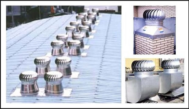
Figure 1. Ventilators on the rooftop of the building.
effect of ventilation and refrigeration at the same time. The second principle is the air convector. It relies on the breeze air to rotate its blades. Its structure is similar to that of a backward-curved fan [2,3]. The curving direction of the blades is opposite to the direction of the rotation. For a centrifugal fan, the air flows in from the axial direction, but after pressurization it flows out from the blade’s radius direction, which forms a spiral air current from the circumference direction. When a wind direction changes, the air convector does not have to change its structure just because of the change of the wind direction. Therefore, the wind power generation may reduce the design of complexity.
In the past, some electric generators driven by a roof ventilator have been developed [3-5]. For example, Daut et al. have reported a new modification of the roof ventilator generator system by adding the extra fins to rooftop ventilator turbine in order to help it to spin faster and more efficiently. In this design, the rubber belting was attached to the moving object of the roof ventilator. The AC generator is connected to the belting area by using a small plastic wheel. When the wind blows on the fins and generates enough drag forces, the roof ventilator will rotate [4]. The plastic wheel of the AC generator and the moving roof ventilator will spin synchronously to generate electricity. However, the rubber belting has to rub against the wheel and will lead to friction that occurs at the belting/wheel interface causing energy loss and is hardly employed. Dangeam et al. used a RFPM (Radial Flux Permanent Magnet) generator for voltage generating. The system comprises of stationary part and rotational part. Stationary part is composed of base and fixed shaft. Rotational part is composed of fan blades and bush that put on the fixed shaft on stationary part. When the air flow on the top of roof or the heat air that lifting to under the roof, it turns the roof ventilator [5]. Since the generator is directly mounted on the bottom of the shaft, it can prevent thermal convection.
To overcome these issues for the rooftop ventilator generator, a small power generation system motivated by a coreless stator AFPM (Axial Flux Permanent Magnet) generator which is driven by the air ventilator has been proposed. AFPM machines are generally regarded as ideally suited whenever low speed is required, such as in direct-drive applications [6]. Compared with other PM machine topologies, the AFPM designs have higher power densities. For a given magnet material and air-gap flux density, radial flux designs have higher rotor moment of inertia; the active weight of the AFPM machines is smaller. Furthermore the AFPM machines have many unique features. For being permanent magnet, they are usually more efficient. As field excitation losses are eliminated, reducing rotor loses significantly. Machine efficiency is thus greatly improved, and higher power density achieved. Also, AFPM machines have thin magnets, so they are smaller than radial flux counterparts. AFPM machine size and shape are important features in applications where space is limited, so compatibility is crucial. The noise and vibration they produce are less than those of conventional machines. Their air gaps are planar and easily adjustable. Also, direction of main air-gap can be varied, so derivation of various discrete topologies is possible. These benefits give AFPM machines advantages over conventional machines in various applications.
In this work, the AFPM generator is assembled at the ventilator base. The system can be installed on the roof, bathroom intake, or at ventilated place to provide a spare source. When the ventilator rotates, the flux of the permanent magnet rotor part moves across the air gap and induces the emf. AFPM machines with coreless stators are regarded as high efficiency and simplicity of construction and very low rotor losses for distributed power generation systems [6-9]. Because of the absence of core losses, a generator with this type of design can potentially be operated at a higher efficiency than conventional machines. Besides, the high compactness and diskshaped profile make this type of machine particularly suitable for mechanical integration with ventilator.
In this paper, a small power generation system motivated by a coreless stator AFPM generator has been designed and fabricated. This generator has two outer disk rotors and one coreless stator in between. NeodymiumIron-Boron (Nd-Fe-B) rare-earth magnets produce the necessary excitation in the generator. These magnets are glued onto the two inner surfaces of rotor disks. After the preliminary design, and for precision study, a two-dimension model of the machine is analyzed using finite element method software. In addition, analytical results will be validated through a series of experiments to demonstrate the usefulness of the system.
2. Design and Fabrication
The main function of the free spinning roof ventilator is to provide fresh air in roof space and living area all year round 24 hours a day free of charge. The additional function of this product is to produce the electrical energy from the roof ventilator that will spin when the wind exist. The consumers not just can enjoy the benefits of the better air ventilation in the house, but also have extra electricity supply for household appliances such as radio, mobile phone charger. The main component of the system is the AFPM generator. It will convert the kinetic energy from the wind to the electricity for our usage. The generated electricity then will go though the AC-DC converter to convert it to Direct Current (DC) voltage. This free electricity has to use the battery charger to allow the charging process running. This to ensure that there will be no back-flow current if the roof ventilator is not functioning. Inverter is use to convert from DC to AC for our AC load usage.
Figure 2 illustrates the schematically of the developed AFPM machine with two outer rotor disks and one coreless stator in between. As it can be seen, round flatshaped high energy Nd-Fe-B magnets are glue onto the inner surface of the two rotor disks. The rotor poles with an opposite arrangement (N-S type) and the stator winding of the machine has no iron core and the surface winding of the stator is perpendicular to the machine shaft. The rotor has a diameter of 200 mm and 30 NdFeB permanent magnets are arranged in an N-S-N-S pattern around the circumference of the rotors. Opposite poles face each other. The diameter and thickness of the NdFeB permanent magnet is 20 and 5 mm, respectively.
The Table 1 has shown the dimensions of the AFPM generator. For the roof ventilator which driving the prototype generator is using 8 inch size because of it’s small size and easy to carry. With the dimensions of the system given in Table 1, the 2-D finite element model of the machine is implemented in the finite element software to be analyzed. In Figure 3, the magnetic flux lines are shown for one pole-pitch of the machine. Figure 3 dem-
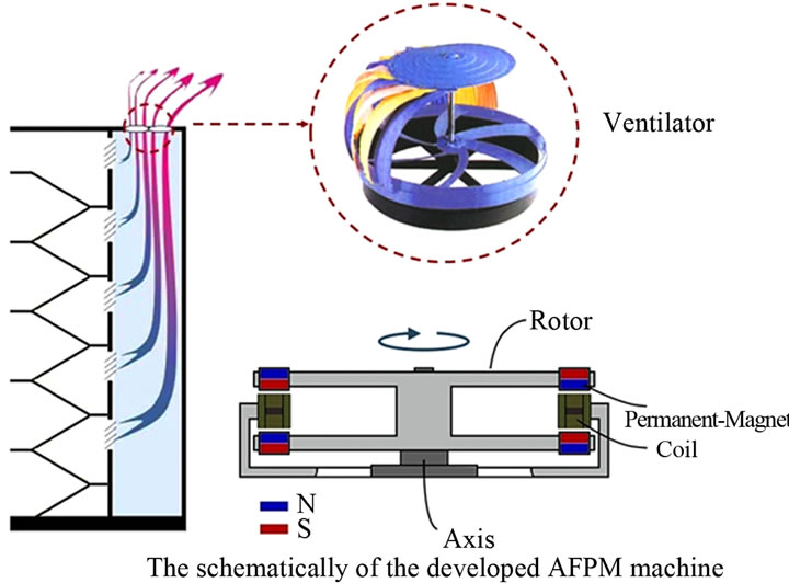
Figure 2. The schematically of the developed AFPM machine.
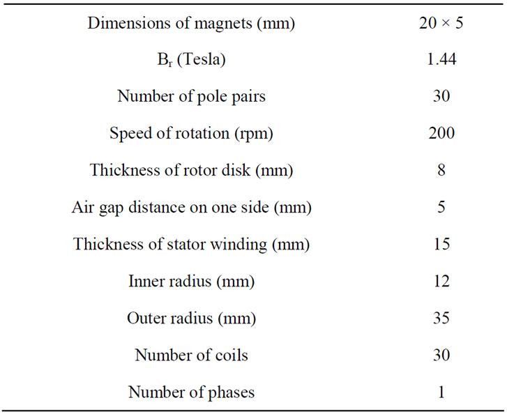
Table 1. The specification of the prototype.
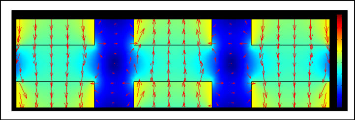
Figure 3. Magnetic flux lines in the machine.
onstrates the flux diagram of motor. It shows that maximum flux density in hotspots is 1.147 T.
The main system construction of this design is shown in Figure 4. It contains the ventilator and the AFPM generator. The AFPM generator is assembled at the ventilator base. When the ventilator rotates, the flux of the permanent magnet rotor part moves across the air gap and induces the emf.
3. Result and Discussion
The prototype of the small power generation system is shown in Figure 5. This is a standard roof ventilator in the market with diameter size, 8 inch. The mechanical aspects of this prototype are just the simple bearing with the proper installation of the components. In this system, research process involved the study how to generate the electricity from the spinning roof ventilator. The important specification of the generator is the torque must below to enable it to start at the low speed.
This test is operated in electrical machines laboratory and essentially to determine the characteristics of the small power generation system. The ventilator is driven by a variable speed DC motor. Experiments are of two types; no-load and on load tests. In the latter cases, 100-Ω resistive loads are used.
Figure 6 shows the output voltage as a function of wind speed in parallel configuration. As shown in Figure 6, the
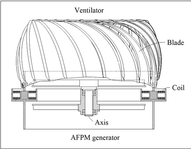
Figure 4. The design of the power generation system.

Figure 5. The prototype of the power generation system.

Figure 6. The output voltage versus rpm.
output voltage is proportional to the speed. With the operating standard of roof ventilation, the speed of roof ventilator must be at least 4 m/sec wind speed or at 85 rpm from roof ventilator speed [4]. To experimentally obtain the performance of the generator at different speeds, the speed is changed from zero to the nominal speed of 200 rpm, which corresponds to the wind speed 4 m/s. The maximum output voltage and current in parallel configuration can achieve 103 V and 0.17 A, respectively. In addition, the output voltage and current with 100 Ω resistive loads are 20 V and 0.13 A, respectively. The output power can achieve 17.5 W at the speed of 200 rpm. Furthermore, we also installs the prototype generator with roof ventilator on the roof (Figure 7). In the outdoor test, the generator is tested by charging 12 V 5 Hr battery. The minimum wind speed for enough charging to battery is below 1 m/s (almost at light air). The output voltage still can achieve 20 V, which is sufficient to charge the battery. In Taiwan, the annual average wind speed exceeds 4 m/s, which corresponds to 400 rpm. At this speed, the output voltage of the designed ventilator generator can achieve 152 V.
4. Conclusion
In this paper, after the introduction of AFPM machines with no iron cores, one typical generator was theoretically designed. Next, with the finite element analysis, the parameters of the generator were calculated. After the construction of the generator, the performance of the generator was experimentally evaluated. AFPM generators are usually driven at low speeds, and hence, to increase the output power, a larger number of pole-pairs are needed. The test is operated in electrical machines laboratory and essentially to determine the characteristics of prototype generator. Based on the experiments, the results of the output voltage which are at no-load and
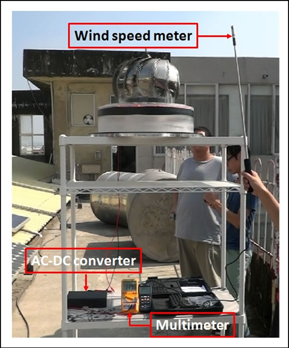
Figure 7. Generator testing with roof ventilator on the roof.
100 Ω resistive loads in parallel configuration are 103 V and 20 V at the speed of 200 rpm, respectively. The output power can achieve 17.5 W at the speed of 200 rpm. Since the AFPM machines have coreless stators, very low rotor loses for distributed power generation systems, and they can be easily driven. For the results after installing the generator on the roof of a building to charge the 12 V battery, the minimum wind speed for enough charging to battery is at 10 rpm. Furthermore, the prototyped of the generator is relatively small and cheap. After the fabricating and testing of the prototype, this system has been proved feasible for practical application.
5. Acknowledgements
The work was financially supported by the National Science Council under contract NSC 101-2221-E-168-023.
REFERENCES
- Wind Is Ravine Ventilator CO. Ltd. http://www.0933772983.com.tw/start.htm
- Backward-Curved Fan. http://www.remco.co.uk/products/bcf.asp
- Y. Ting, H. Gunawan, A. Sugondo, K. L. Hsu and J. T. Teng, “Analysis and Design of Roof Turbine Ventilator for Wind Energy Harvest,” Proceedings of the 2nd International Conference on Mechanical and Electronics Engineering (ICMEE), Kyoto Japan, 1-3 August 2010, pp. 265-269.
- I. Daut, C. Shatri, M. Irwanto, A. N. Syafawati and S. S. Shema, “Power Generation Roof Ventilator,” Proceedings of the 2011 International Conference on Environment and Industrial Innovation IPCBEE, Singapore, 26- 28 February 2011, pp. 183-187.
- S. Dangeam, “An Electric Generator Driven by a Roof Ventilator,” Energy Procedia, Vol. 9, 2011, pp. 147-158. http://dx.doi.org/10.1016/j.egypro.2011.09.016
- A. Mahmoudi, N. A. Rahim and W. P. Hew, “Axial-Flux Permanent-Magnet Machine Modeling, Design, Simulation and Analysis,” Scientific Research and Essays, Vol. 6, No. 12, 2011, pp. 2525-2549.
- J. F. Gieras, “Permanent Magnet Motor Technology: Design and Applications,” 3rd Edition, CRC Press, Boca Raton, 2009. http://dx.doi.org/10.1201/9781420064414
- J. F. Gieras, R. J. Wang and M. J. Kamper, “Axial Flux Permanent Magnet Brushless Machines,” 2nd Edition, Springer, Berlin, 2008. http://dx.doi.org/10.1007/978-1-4020-8227-6
- N. F. Lombard and M. J. Kamper, “Analysis and Performance of an Ironless Stator Axial Flux pm Machine,” IEEE Transactions on Energy Conversion, Vol. 14, No. 4, 1999, pp. 1051-1056. http://dx.doi.org/10.1109/60.815027