Engineering
Vol.5 No.8(2013), Article ID:35525,5 pages DOI:10.4236/eng.2013.58077
On the Characteristic of Orthogonality for Multi-Carrier-Based Systems
1Department of Electrical Engineering, Dayeh University, Taiwan
2Department of Multimedia Animation and Application, Nan Kai University of Institute, Taiwan
Email: *jchen@mail.dyu.edu.tw
Copyright © 2013 Hao Wei Huang et al. This is an open access article distributed under the Creative Commons Attribution License, which permits unrestricted use, distribution, and reproduction in any medium, provided the original work is properly cited.
Received June 3, 2013; revised July 3, 2013; accepted July 10, 2013
Keywords: CFO; CPN; FBC; Multi-Carrier Modulating
ABSTRACT
The dominate factors caused by reasons of losing the orthogonality in fading channel including FBC (fading branch correlation), CFO (carrier frequency offset), and even the CPN (carrier phase noise) are novel discussion in this letter. The first one factor causes the ISI (inter-symbol interference), and, however, the latter two will lead to the phenomenon of CPE (common phase error) and ICI (inter-carrier interference). On the other hand, they will lead to the loss of orthogonality for the radio system with multi-carrier modulating schemes, i.e., both them mainly deteriorate a wireless communication system. Eventually, in this letter not only the analytical expressions are derived, but a three dimension numerical results from the analysis involve the three parameters also illustrated is.
1. Introduction
It is known that the important disadvantage for a multicarrier system is the sensitivity to the phenomenon of CPN (carrier phase noise) and CFO (carrier frequency offset), which are mainly caused by the reason of frequency mismatch. CPN and CFO which can be caused by Doppler shift due to the vehicle motion or the frequency differences between the transmitter and receiver oscillator. CPN and CFO are going to incur CPE (carrier phase error) and ICI (inter-carrier interference) eventually. This factor is researched and published in many studies [1,2]. On the basis of ICI considered caused by CFO error in different kinds of propagation fading channels, and the evaluation of performance for an MCCDMA-MIMO system was held in [3]. The FBC (fading branch correlation) problem occurred in a multi-carrier system that combines with diversity reception is investigated by several researches [4,5].
Apart from the two degradation factors claimed previously, in fact, CPN is considerable for being taken into the evaluation of system performance for the multicarrier modulated systems. In the past, for instance, in [6] the impact of the phase on the system performance for OFDM system is discussed and published. Jointing channel estimation and ICI reduction scheme for compensation the effects of CPN and multipath channel is illustrated until recently in [7].
Nevertheless, reviewing the aforementioned publications which considered almost the phenomena of FBC and CFO independently; however, to take account of the relationship among FBC, CFO, and CPN into the analysis of performance for a multi-carrier system is necessary. Besides, the letter is also to address the issue of delay access time relating to those factors happen in the fading channel.
2. System Models of a Multi-Carrier
2.1. Consider the Jointing of FBC and CFO
In a multi-carrier modulating diversity reception system to ensure frequency nonselectivity for each subchannel to select an enough large number of subcarrier is often necessary. Consequently, this also causes the reduction of frequency separation between adjacent subcarriers. Consider an multi-carrier modulating system experiencing a WSSUS (wide sense stationary uncorrelated scattering) frequency-selective fading channel, and each user is with impulse response . Since the subchannel bandwidth is assumed less than the channel coherent bandwidth, the consideration of uncorrelated fading characteristics between the subchannel has became invalid. It also means that the FBC should exist between subchannels as
 , where
  is the system bandwidth, and
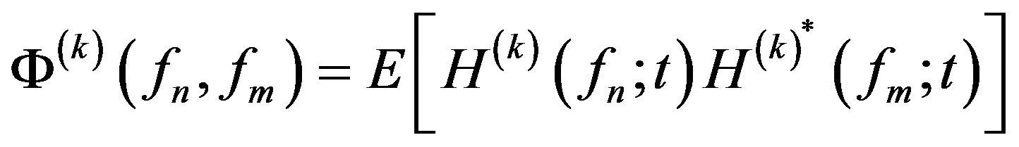
  represents the coherence bandwidth. The statistical model between the n-th and the m-th subchannel fading coefficients experienced by the k-th subscriber can be characterized as the frequency correlation function and written as
 (1)
(1)
where  denotes the Fourier transform of
 , and the superscript * indicates the complex conjugate. Provide that the assumption of fading channel is with the Rayleigh fading process among all M subcarriers, the covariance matrix for the user k can be described as
 (2)
(2)
where the FBC effect has been involved in this formula.
2.2. Consider the Model of CPN
It is well known that the performance of a multi-carrier modulating system will become inferior due to the CPN arising from the phase noise, which discussed in this subsection. Generally speaking, CPN is characterized as a random process that is proven to be more complicated than CFO. To estimate precisely the frequency or phase in the demodulator’s oscillator (local oscillator) is the most important job for RF transceivers. Generally, an oscillator at the demodulator can be implemented in two means which are phase locked loop (PLL) and free-running oscillator when the processing of frequency conversion. The normal expression of the ideal modulated tone at the output of an oscillator,
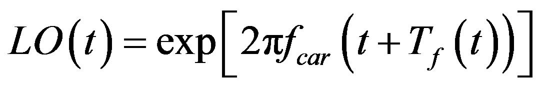 where
where 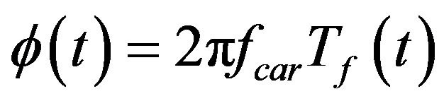 is phase deviation or a changing time shift in the periodic output of the unperturbed oscillator and named as phase noise. Usually, phase noise is discussed with different modular for oscillators realized by using PLL (phase locked loop) and free-running oscillator. In the latter mode
  is traditionally characterized as a standard Wiener process or continuous Brounian motion process,
  , i.e.,
 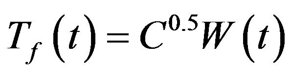 in which
  is with an accumulated Gaussian RV with unit variance
 , and a scalable parameter
  denotes the attenuation of the oscillator PSD (power spectral density) around the first harmonic [7]. The relationship of them depends on the value of CFO,
  , and can be calculated as
 (3)
(3)
for  and small values of C, and
 (4)
(4)
for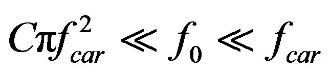 , where
 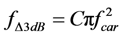 is defined as the phase noise 3-dB bandwidth.
Consequently, after the signal impaired by the CFO and CPN arrives at the input of receiver of an asynchronous multi-carrier system during one bit interval, and which can be written as
 (5)
(5)
where  and
and
 (6)
(6)
where  has been shown in (1) for the 0-th user, and the total phase generated at the receiver is expressed as
 (7)
(7)
where the phase deviation,  , and
, and  denotes the normalized frequency offset due to the frequency mis-matched between transmitter receiver and defined as
 , where
  is the frequency offset of the
  -th user, and the space between subcarriers of each user is defined as
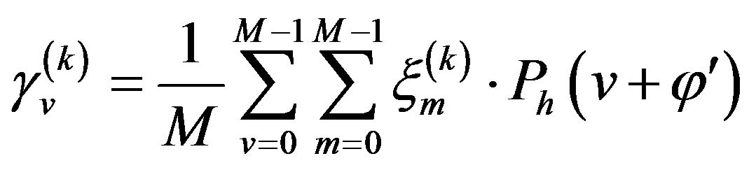
  . When the carrier frequency offset is involving in the received signal for the referenced subscriber, after then, it can be obtained by the v-th FFT (fast Fourier transform) input corresponding to the MAI (multiple access interference) without noise and expressed as
 (8)
(8)
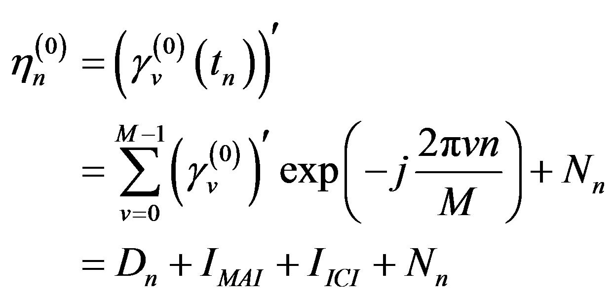
The received signal expressed in the previous equation is going to be passed into a block with FFT function as shown in Figure 1. After the complex-valued M samples, which are sampled within an multi-carrier symbol at the time instant  of
of  accompanied by the AWGN (additive white Gaussian noise) at the output of FFT block can be determined by
 (9)
(9)
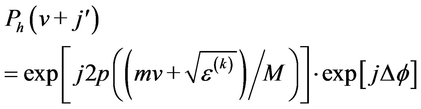
where the last component,  , expresses the contribu-
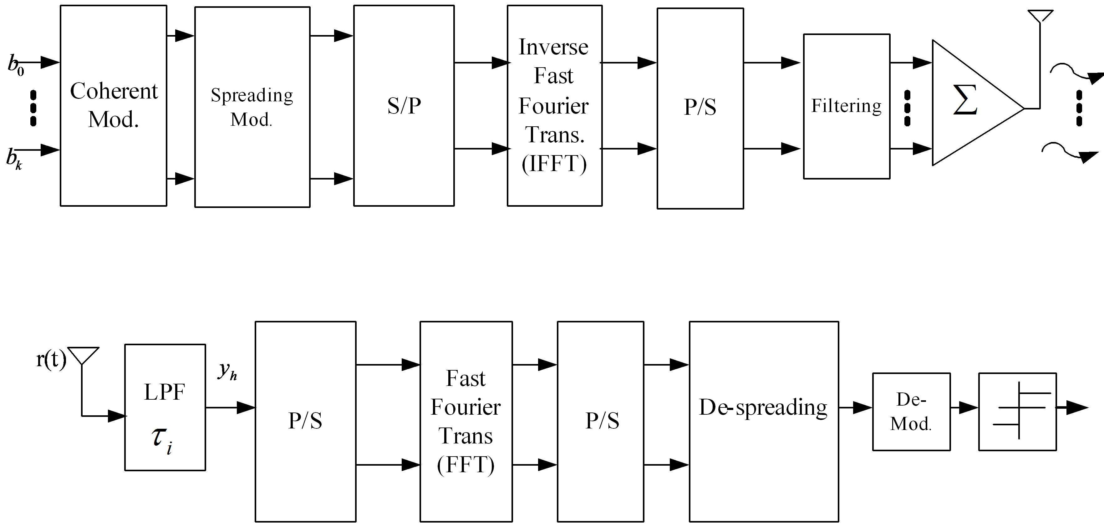
Figure 1. A multi-carrier system block diagram.
tion of passing the AWGN into the FFT block,  is the desired signal component of the referenced subscriber, and
  and
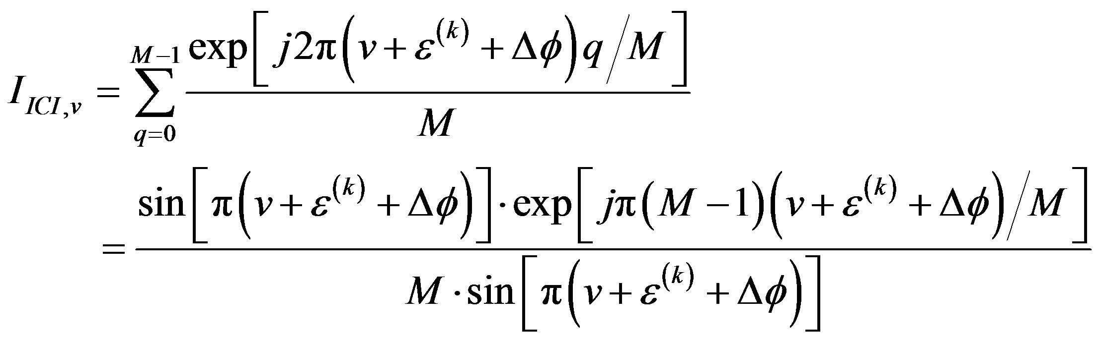
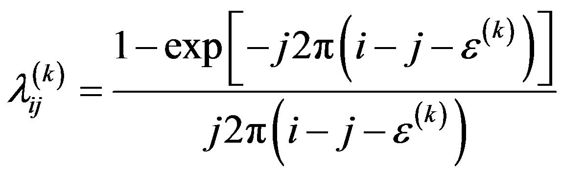
and  denote MAI and ICI, respectively. The ICI (inter-carrier interference), which definitely deteriorates the system performance, is generated by including CFO and CPN phenomena. It is well known that the phase noise is equivalent to a random phase modulation of the carrier, and it is inherently appear in oscillator of both transmitter and receiver. However, the small amount of phase noise is considered in this paper during one Multi-carrier symbol. This reason results in the case with phase noise only at the end of the receiver. As the CFO happens to the v-th subcarrier of a referenced user operating in Multi-carrier system within a single cell, it is able to be shown and easily expressed with a geometric series as [8]
 (10)
(10)
where  has been defined in (7). In this study, now we focus on the discussion of jointing the impact of FBC, CFO and CPN in an asynchronous multi-carrier system. However, it is worthy to explore the relationship between FBC, CFO and CPN each other. As the aforementioned for the purpose of keeping the assumption of uncorrelated fading characteristics between subchannel on effective, to maintain the condition of
  is necessary. On the other hand, when the inverse fact happens, i.e., when the condition
  is valid, channel correlation will definitely stay in the subchannels. Therefore, if the event of CFO outcome is considered as a random process, then the probability of the event to generate CFO with the former condition,
  , will become more larger than that is of the latter condition,
 . This is due to the frequency separation,
  , decreasing in the former case. Mathematically express this event as
 (11)
(11)
where  has been defined in (4). Accordingly, the function between FBC and CFO can be determined as
 (12)
(12)
where integer i and j,  , represent different subchannel, respectively, and
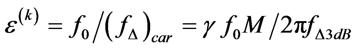
  is the normalized CFO of user k. Now, in order to include both all of the parameters, FBC, CFO, and CPN into the accounting for system performance evaluation of the Multi-carrier system, the normalized CFO,
  , for the k-th user is needed to be modified as,
 (13)
(13)
where  is changed as normalized by the phase noise 3-dB bandwidth,
  is expressed as
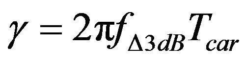 . The numerical analysis of the relationship between FBC, CFO and CPN is shown in Figure 2 where Z-Axis is presenting FBC (
 ) which functions of CFO (
 ) and CPN (
 ). Different subchannel numbers are indexed by
  and
and , i.e.,
 . In case in the same subchannel situation,
  , it is clear to understand that the CFO will increase to follow the FBC decrease, since the separation now is zero. However, it is trivial for this situation because nothing could occur in the state in which is staying in the same subchannel. Once, the separation becomes nonzero between subchannel, it is worthy to note that the results will change inversely. For instance, the results from the case of
  are totally different in that of the case of
 . Moreover, the corresponding results from the assumption with
  to
to  are also illustrated for comparison in the pictorial of Figure 2. It is reasonable to claim that the much larger separation between different subchannels, the little correlation existing in it is. The fact of (12) has been proved and shown in the results of Figure 2.
So far, in addition to determining the result of the signals propagating between the transmitter and the receiver of an multi-carrier modulating system, in order to complete the analysis involving FBC parameter now to determine the correlated-Rayleigh channel model of the small-term channel is necessary. Except to consider the propagation channel is with multipath delay and the received signal of different users is independent of each other, the received path numbers is assumed equal to the number of subcarriers too. The fading path gain ,
,  are characterized as Rayleigh distribution. Since the fading branch correlation is discussed in this study, the independent of receiving branch can not be hold. Moreover, the JPDF (joint probability density function) of the assumed correlated channel proposed in [6] adopted as in analytical calculation. Apart from, the way to algebraically deal with the fading correlated channel in each received branch is a difficulty matter, however, a novel method by using of the generalized Laguerre polynomial to expand the JPDF can be derived and obtained as
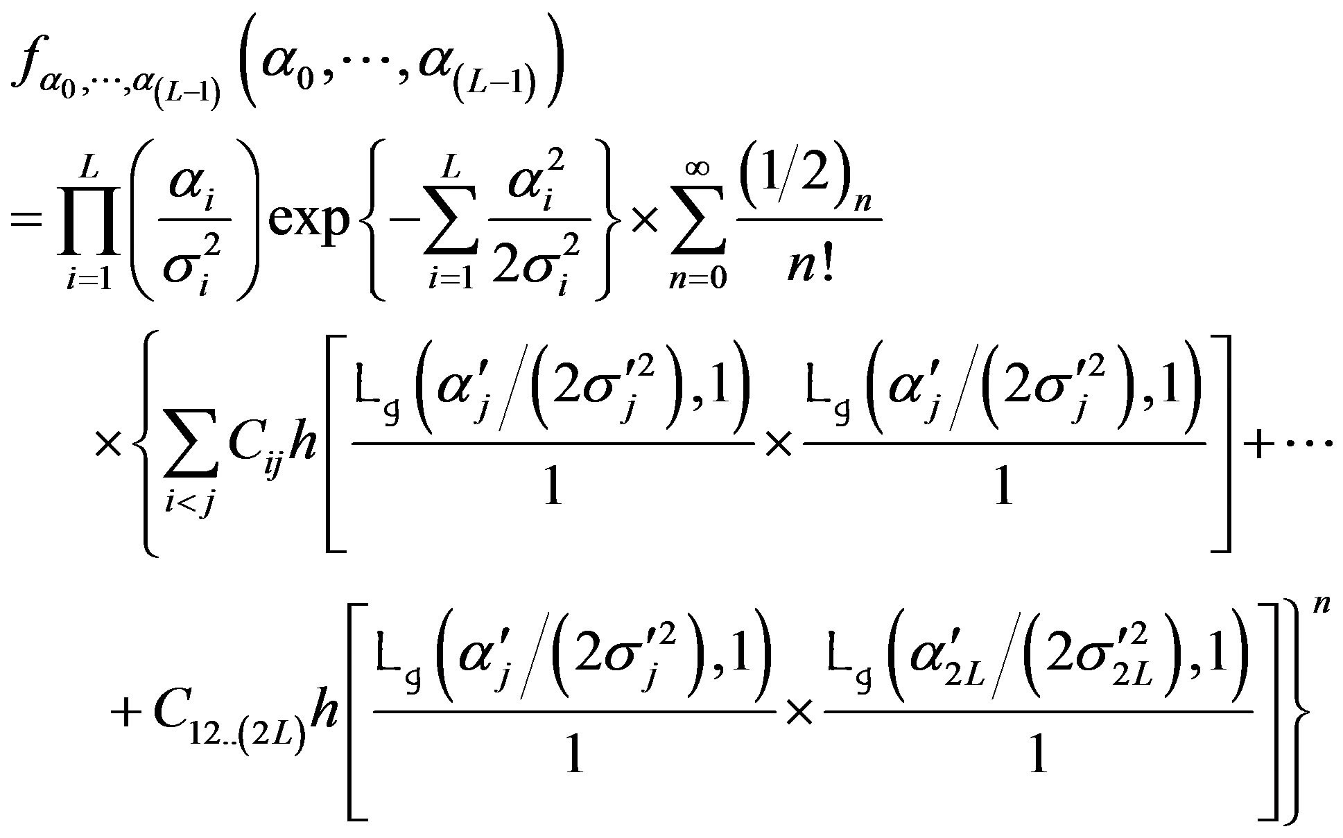 (14)
(14)
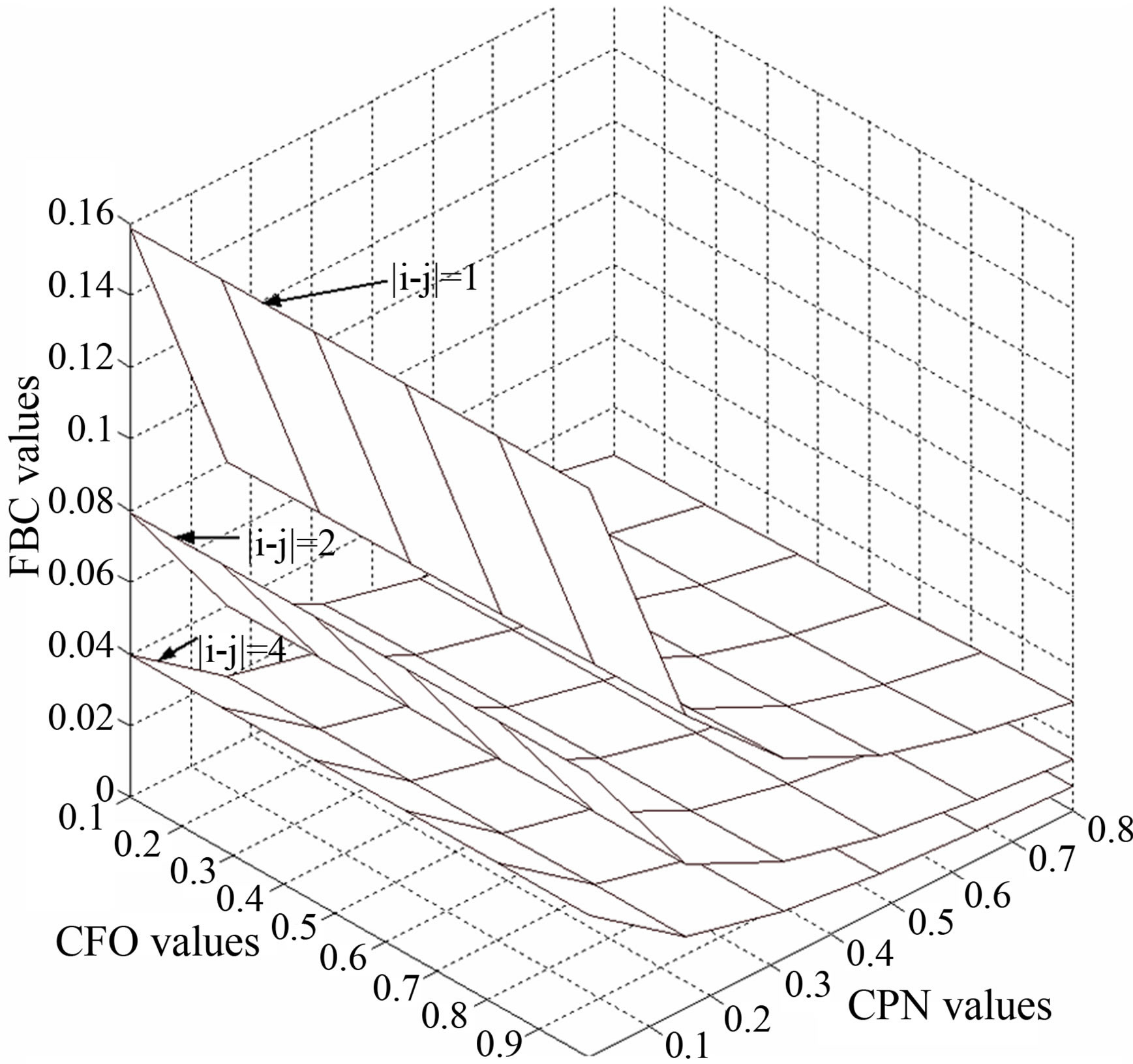
Figure 2. The plots of relationship between CFO and FBC with different subchannels separation.
in (14)  is the generalized Laguerre polynomial of degree
 , it is defined as [4]
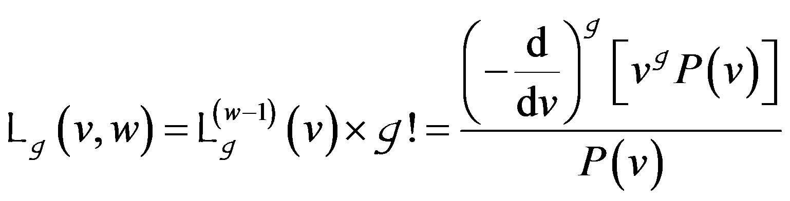 (15)
(15)
and  in (14) is a symbol of the n-th power of a multinomial. Traditionally, it exists a little troublesome to obtain the JPDF of L corrected variables with Rayleigh distribution directly. Nevertheless, apply the MGF (moment generating function) or CHF (characteristic function) are alternately the method for the best way to calculate the joint moment generating function. The formula derived in (14) can be easily adopted as the general form in system analysis for the multi-carrier system. Especially, in discussion about the multipath fading issues for the multi-carrier system, it makes plenty contribution.
3. Numerical Explanation
To figure out the comparison results from the three factors FBC, CPN and CFO simultaneously, the figures are shown with a 3-Dimension curve in Figure 2. In which the vertical axis indicates the different FBC values and CFO (names as X-axis) and FBC (named as Y-axis) with distinct values are denoted in the other two axes, respectively. Values with 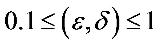 are assigned to CFO and FBC. CPN definitely varies with the different values of CFO and FBC. There are three layers are corresponding to difference number of sub-carriers, i.e.
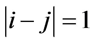 ,
, 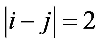 , and
, and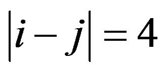 . The fact can be easily seen is that the CPN will become decrease with the distance between sub-carriers is increase. For instance, the CPN equals 0.04 when the difference between sub-carrier is 4 and the CPN is equivalent to 0.16 on the condition of that is 1. It is finally worth to note that the various between FBC and CPN are much larger than that between FBC and CFO. On the other hand, it is valuable to claim that the system performance of a multi-carrier system is dominated by most of both the CPN and FBC parameters.
4. Conclusion
On the basis of both considering fading channel and including the variate of the local oscillator in the evaluation of system performance for a multi-carrier system is investigated in this letter. In order to figure out the comparison results from the three factors mentioned previously, the plots are presented with many 3-Dimension curves. The numerical results clarify that the assumption of independence between the sub-carriers is invalid under some conditions, such as the insufficient separation between sub-carrier and/or the length of the maximum access delay time is longer than that of the duration of the sub-carrier.
REFERENCES
- S. L. Talbot and B. F. Boroujeny, “Mobility and Carrier Offset Modeling in OFDM,” Proceeding of IEEE Globecom, Washington DC, 26-30 November 2007, pp. 4286- 4290.
- W. M. Jang, L. Nguyen and M. W. Lee, “MAI and ICI of Synchronous Uplink MC-CDMA with Frequency Offset,” IEEE Transactions on Vehicular Technology, Vol. 57, No. 4, 2008.
- A. Sundhar, P. Kamarajar and P. Dananjayan, “Capacity Enhancement in MCCDMA-MIMO System Using Iterative Water Filling Approach Based Power Distribution Method,” IEEE Transactions on Third International Conference on Communications, Computing Communication & Networking Technologies (ICCCNT), 2012, pp. 1-5.
- J. I.-Z. Chen, “Performance Analysis for MC-CDMA System over Singleand Multiple-Cell Environments in Correlated-Nakagami-m Fading,” IEICE Transactions on Communication, Vol. E90-B, No. 7, 2007.
- P. M. Shankar, “Macrodiversity and Microdiversity in Correlated Shadowed Fading Channels,” IEEE Transactions on Vehicular Technology, Vol. 58, No. 2, 2009, pp. 727-732. doi:10.1109/TVT.2008.926622
- D. Petrovic, W. Rave and G. Fettweis, “Effects of Phase Noise on OFDM Systems with and without PLL: Characterization and Compensation,” IEEE Transactions on Communication, Vol. 55, No. 8, 2007, pp. 1607-1616. doi:10.1109/TCOMM.2007.902593
- R. Corvaja and A. G. Armada, “Joint Channel and Phase Noise Compensation for OFDM in Fast-Fading Multipath Applications,” IEEE Transactions on Vehicular Technology, Vol. 58, No. 2, 2009, pp. 636-642. doi:10.1109/TVT.2008.927719
- Z. Du, J. Cheng and N. C. Beaulieu, “Accurate Error-Rate Performance Analysis of OFDM on Frequency-Selective Nakagami-m Fading Channels,” IEEE Transactions on Communication, Vol. 54, No. 2, 2006.
NOTES
*Corresponding author.