Engineering
Vol.5 No.5(2013), Article ID:31692,6 pages DOI:10.4236/eng.2013.55057
Finite Element Modeling of Stability of Beam-Column Supports for Field Fabricated Spherical Storage Pressure Vessels
Department of Mechanical Engineering, University of Ibadan, Ibadan, Nigeria
Email: oluwoleo2@asme.org
Copyright © 2013 Oludele Adeyefa, Oluleke Oluwole. This is an open access article distributed under the Creative Commons Attribution License, which permits unrestricted use, distribution, and reproduction in any medium, provided the original work is properly cited.
Received January 29, 2013; revised March 1, 2013; accepted March 8, 2013
Keywords: Field-fabricated; Spherical Storage Pressure Tank; Beam-Column Support; FEM
ABSTRACT
Spherical pressure vessels in large sizes are generally supported on legs or columns evenly spaced around the circumference. The legs are attached at or near the equator of the sphere. This research work focussed on flexural-torsional buckling of beam-column supports of field fabricated spherical pressure vessels using finite element analysis. Flexuraltorsional buckling is an important limit state that must be considered in structural steel design and it occurs when a structural member experiences significant out-of-plane bending and twisting. This research has therefore considered the total potential energy equation for the flexural-torsional buckling of a beam-column element. The energy equation was formulated by summing the strain energy and the potential energy of the external loads. The finite element method was applied in conjunction with the energy method to analyze the flexural-torsional buckling of beam-column supports. To apply the finite element method, the displacement functions are assumed to be cubic polynomials, and the shape functions used to derive the element stiffness and element geometric stiffness matrices. The element stiffness and geometric stiffness matrices were assembled to obtain the global stiffness matrices of the structure. The final finite element equation obtained was in the form of an eigenvalue problem. The flexural-torsional buckling loads of the structure were determined by solving for the eigenvalue of the equation. The resulting eigenvalue equation from the finite element analysis was coded using FORTRAN 90 programming language to aid in the analysis process. To validate FORTRAN 90 coding developed for the finite element analysis and the methodology, the results given by the software were compared to existing solutions and showed no significant difference P > 0.05.
1. Introduction
Leg supports in spherical LNG pressure storage tanks can be modeled as beam-column members since they are also subjected to bending and axial compression. Loading is done such that bending occurs about the strong axis [1]. End moments and transverse loadings produce primary bending while axial forces produce secondary moments [1]. Out-of-plane bending and twisting occurs when loading reaches a limiting value. It is said that out of plane failures occur suddenly in members with greater in-plane bending stiffness than torsional or lateral bending stiffness [2]. In thin beams, elastic lateral-torsional buckling load is the buckling load while in beam-columns, this is referred to as the elastic flexural-torsional buckling load. We are interested in flexural-torsional buckling loads in this work. This buckling load is said to be influenced by several factors [3]:
1) the cross-section of the member;
2) the unbraced length of the member;
3) the support conditions;
4) the type and position of the applied loads, and the location of the applied loads with respect to the centroidal axis of the cross section.
The goal for field fabricated beam-column supports stability analysis is to determine its flexural-torsional buckling loads with the aim of designing against flexural-torsional either by changing the first two influencing factors since the last two may not be changeable.
2. Literature Review
[4] in his paper examined buckling behaviour of an I-beam under combined axial and horizontal side loading. Theoretical formulation was developed to determine the critical buckling load for such combined loading configuration from the elastic static theory. Both, the beam deflection theoretical model and the critical load capacity were derived for this combined loading condition. He utilized finite element analysis to apply the axial load on the beam at various configuration locations and it was shown that this application location determines the buckling behaviour and the critical load of the buckling of the I-beam. Elastic flexural buckling of doubly symmetric columns with oblique restraints under concentric loading was examined by [5]. Oblique restraints cause coupling between the principal axis deflections and rotations, and the flexural buckling mode involves simultaneous bending about both principal axes. This paper discussed the nature of oblique end restraints, summarised their finite element analysis, presented examples of their effects on the elastic buckling of columns, and demonstrated the design of columns with oblique restraints.
Based on a non-linear stability model, analytical solutions were derived for simply supported beam-column elements with bi-symmetric I-sections under combined bending and axial forces by [6]. A unique compact closed-form was used for some representative load cases needed in design. It included first-order bending distribution, load height level, pre-buckling deflection effects and presence of axial loads. The proposed solutions were validated by recourse to non-linear FEM software where shell elements were used in mesh process. The agreement of the proposed solutions with bifurcations observed on non-linear equilibrium paths was good. It was proved that classical linear stability solutions underestimate the real resistance of such element in lateral buckling stability especially for I section with large flanges. First-order stochastic perturbation expansions and Monte Carlo simulation techniques were used to study the effects of random elastic moduli on the post-buckling response of simple frame structures by [7]. This analysis provided a deeper understanding of the variability in anticipated postbuckling response that could prove highly valuable for design considerations. The stochastic perturbation approximation to the mean and variance of the post-buckling behavior was evaluated as a potential means of curtailing the need for a high number of sample simulations. A new formulation for lateral buckling of beams comprising bisymmetric sections was proposed by [8]. The formulation employed a coupled lateral buckling functional to investigate the lateral buckling behaviour of a class of beams comprising bisymmetric sections. While retaining the coupled modes of displacements at buckling, the formulation focused attention on the need to reduce the number of degrees of freedom per element so that the solution process can be carried out on small microcomputers.
3. Finite Element Methodology
3.1. Model Assumptions
Modeling assumptions are:
1) The entire structure remains elastic prior to buckling i.e. members are long and slender.
2) The members have symmetric cross sections.
3) The cross sections of the members do not distort in their own plane after buckling.
4) The members are perfectly straight.
5) Local buckling does not occur.
3.2. Finite Element Procedure
This segment focuses on the governing equations for solving flexural-torsional-buckling load of a beam structure and the finite element equations. The method used by Erin [1] is adopted in the present work. Thus, element stiffness matrices and element geometric stiffness matrices from the energy equation are assembled to form global stiffness matrix. Boundary conditions are applied to the matrix and the partitioned global stiffness and geometric stiffness matrices used to solve for the buckling loads. For this research, the structure under analysis is beam-column of supports of field fabricated spherical storage pressure vessel. Advantage is taken of the symmetrical nature of the system. The beam-column element has six nodal degrees of freedom making a total of twelve degrees of freedom for each element.
3.2.1. Beam Representation
The coordinate system is as shown in Figure 1 with the axes orthogonal. The z-axis runs along the length of the beam through the centroid of the cross section of the structure. The x-axis is taken as the major axis and y-axis the minor axis prior to buckling.
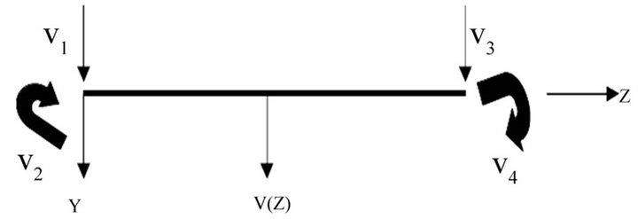
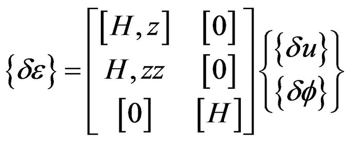
Figure 2 shows the element degrees of freedom. Figure 2(a) shows the element with the lateral bending displacement  at a distance z along the element and the four out-of-plane nodal displacements
 , and
, and .
.  and
and  are the out-of-plane lateral nodal displacements at nodes whilst
  and
and  are out-ofplane nodal rotations.
Figure 2(b) shows the element with in-plane bending
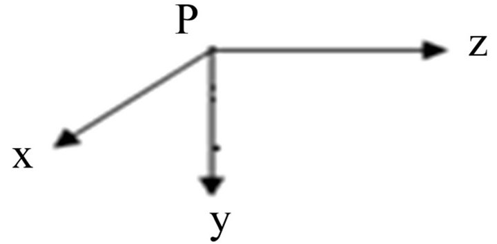
Figure 1. System coordinate system.
 (a)
(a)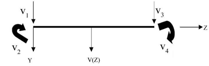 (b)
(b)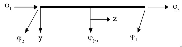 (c)
(c)
Figure 2. Element degrees of freedom.
displacement  at a distance z along the element and four in-plane nodal displacements
 ,
,  ,
,  , and
, and .
.  and
and  are the in-plane nodal displacements whilst
  and
and  are the in-plane nodal rotations.
The beam showing torsional rotational displacement  at a distance z along the element and four nodal displacements,
 and
and , is presented in Figure 2(c). Φ1 and
  are the torsional rotations at nodes while,
  and
and  are the torsional curvatures.
3.2.2. Displacement Function
The displacement functions for the displacements,  and
and , are taken to be cubic to satisfy continuity conditions after [1].
 (1)
(1)
where
 (2)
(2)
and
 (3)
(3)
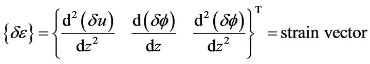
Evidently the first variationals can be expressed as
 (4)
(4)
 (5)
(5)
 (6)
(6)
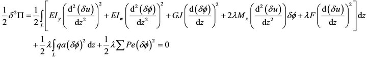
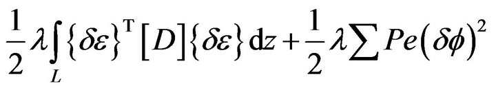
The element stiffness matrix is derived using the energy methods discussed by [1]. The total potential energy equation for the complete structure is in the form of
 (7)
(7)
which re-cast into an applicable equation for finite element analysis is [1]:
 (8)
(8)
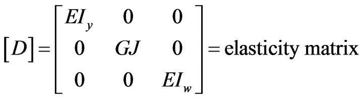
where  second variation of the element strain energy
  second variation of the work done on an element.
  is the buckling factor by which the initial load set is multiplied to obtain the buckling load set. The beam-element strain energy and the work done can be expressed as [1]:
 (9)
(9)
which re-cast is:
 (10)
(10)
where 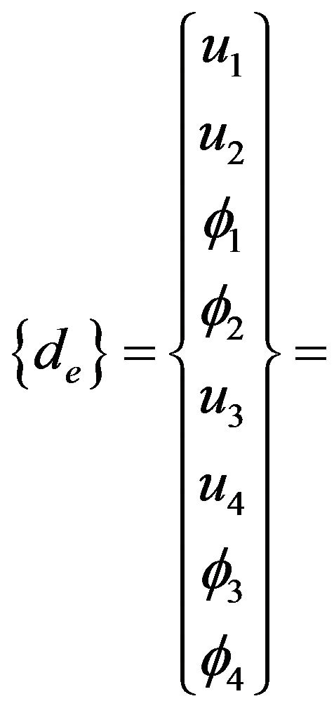 local nodal displacement vector
 buckling factor
 the element local stiffness matrix
 the element local geometric matrix associated with the initial load set.
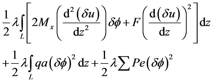
The energy Equation [7] in terms of initial buckling load set is written as [1]
 (11)
(11)
The first three terms of the equation contribute to the element elastic stiffness matrix,  , and the last four terms of the equation contribute to the geometric stiffness matrix,
 .
.
3.3. Element Elastic Stiffness Matrix
The contribution to the element elastic stiffness matrix ,
,
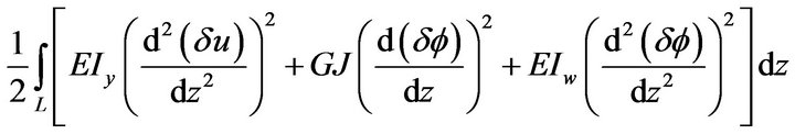 (12)
(12)
can be re-cast as;
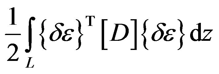 (13)
(13)
where
 (14)
(14)
 (15)
(15)
Substituting Equations (4)-(6) into Equation (14) gives
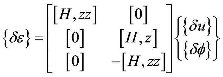 (16)
(16)
Substituting Equation (16) into Equation (13) gives the stiffness matrix,  in terms of the shape function.
3.4. Geometric Stiffness Matrix
The contribution to the element geometric stiffness matrix from Equation (11):
 (17)
(17)
can re-cast as
 (18)
(18)
where
 (19)
(19)
 (20)
(20)
Substituting Equations (4)-(6) into Equation (25) gives
 (21)
(21)
Substituting Equation (21.0) into Equation (18.0) gives the geometric stiffness matrix,  in terms of the shape function,
 .
.
4. Stability Analysis
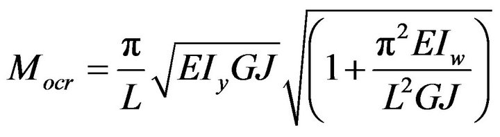
CASE 1: A simply supported beam subjected to equal end moments is shown in Figure 3. The beam is of hollow circular section and the properties for the beam are listed in Table 1. The simply supported beams considered in this case is single span beam which is simply supported both in-plane and out-of-plane. An in-plane simply supported beam is fixed against in-plane transverse deflections, but it is unrestrained against in-plane rotations. An out-of-plane simply supported beam is fixed against out-of-plane deflections and twist rotations, but is unrestrained against minor axis rotations and against warping displacements.
The closed form solution of the critical moment for a beam of length L with simply supported ends is given by [9] is written below.
 (30)
(30)
Beam properties for case 1 are:
Young’s Modulus of Elasticity (ksi) = 3000 Shear Modulus of rigidity (ksi) = 12,000 Second Moment of Inertial about Y-axis (in4) = 345 Second Moment of Inertial about Y-axis (in4) = 1070

Figure 3. Simple beam with equal end moment.
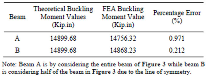
Table 1. FEA and closed form solutions for buckling for case 1.
Moment warping (in6) = 124,000 Polar Moment of Inertia (in4) = 12.9 Cross Sectional Area (in2) = 12 Beam Length (in) = 300 The results of a buckling analysis of the structure conducted with the program along with the closed form solution of the critical moment are presented in Table 2.
CASE 2: A continuous beam (Figure 4) is considered in this case but it is assumed that the beam has the same properties as the beam considered in Case 1. [10] gives the closed form solution of the critical moment for a continuous beam of length L with simply supported ends as:
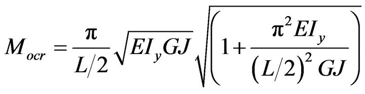 (31)
(31)
CASE 3: A field fabricated spherical pressure vessel with leg supports is considered in this case. Each of the leg support is simply supported beam-column with one fixed end and the other end is simply supported. The beam-column properties of case 1 are assumed for this case. The vertical load carried by each leg is eccentrically from the beam centroid, thereby causing an applied moment on the leg. Represented below in Figure 5 is the typical representative of vertical beam column support. Point one is the end of the beam that is attached to the spherical shell while point 2 is the end of the beam support that bolted to the foundation. In this case, point one
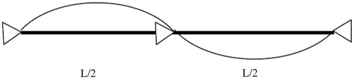
Figure 4. Plan view of a beam with intermediate restraints.
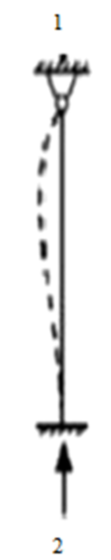
Figure 5. Typical beam-column.
has all has rotation free and translation fixed degrees of freedom. End 2 has both rotation and translation degrees of freedom fixed. The dotted line represents the buckling/deformation shape of the column.
5. Results and Discussions
An idealized simply supported beam is a fundamental case of restrained beams. The closed form solution for beams subjected to uniform bending moment is based on the constraint conditions of idealized simply supported beams [2] and is defined as:
• Both ends fixed against vertical in-plane deflection but unrestrained against in-plane rotation, and one end fixed against longitudinal horizontal displacement
• Both ends fixed against out-of-plane horizontal deflection and twist rotation but unrestrained against minor axis rotation and warping displacement.
[10] further stated that if boundary conditions of a member are different from those of the idealized simply supported beam and the beam segment is subjected to a uniform bending moment, the elastic beam capacity can be expressed as:
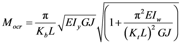 (32)
(32)
The effect length factor Kb corresponds to the lateral effect while Kt corresponds to the twisting restraint. For design purpose, [10] stated that “it is often difficult to judge the exact restraint conditions for a beam segment” and therefore recommended that the effective factor to be taken as:
1.0 if both ends are simply supported 0.7 if one end is simply supported and the other end is fixed 0.5 if both ends are fixed A conservative condition is taken if restraint conditions are doubtful and in which case the effective length factor is taken as one.
In case 1 considered above, both ends are simply supported and therefore, effective length factor used is 1.0. Beam A of case 1 is analysed using FEM on the entire beam while for beam B; line of symmetry of the beam was put into consideration. Comparing FEA buckling moment values with the values given by closed form equation, percentage errors given for both options are acceptable (Table 1).
A continuous beam refers to member with lateral restraint(s) between its end supports as shown in Figure 4. These lateral bracings can significantly increase the buckling moment of the beams and they change the beam’s buckle shape. The simplest case is a simply supported beam with additional lateral bracing at mid-span. When this beam is subjected to a uniform bending moment, the lateral buckling mode will be a complete sin wave as shown in Figure 4. Therefore, the effective length equals to the half of the length of the beam, and the corresponding critical can be calculated accordingly.
When a continuous beam has more than two lateral bracings, partial end restraints will develop between adjacent spans. Theoretically, lateral buckling load depend on the relative stiffness of the segments, the type of bracing or constraint used for the intermediate support, and the type and the relative magnitude of the loads on the beam. In practice, most of these parameters are impossible to quantify [9]. Commonly, the critical load for each segment of a continuous beam is evaluated separately. The selection of a K value for each of beam segment is often based on engineering intuition with the assumption that each segment is simply supported. The lowest value of the critical loads is taken as the buckling of the continuous beam [10]. The method neglects the interactions between each beam segments but the results are generally conservative [10].
In Case 2, two options are considered. For beam A, FEA was used for the entire beam with three nodal points. For beam B, one segment of the beam was considered. The closed form and FEA values for buckling moments are tabulated. The percentage errors for the two beams under this case give 4.41 and 4.02 respectively (Table 2). The buckling moment values given by closed form equations is lower than buckling values given by FEA for both options. This can be deduced that the closed form equation gives conservative values for buckling moment for both beams. This is in agreement with [9].
The theoretical buckling moment of case 3 was determined using 0.7 as the effective factor in equation-(32). The percentage deviation when comparing with the FEA value is 0.16164 (Table 3).
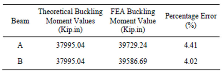
Table 2. FEA and closed form solutions for buckling for Case 2.
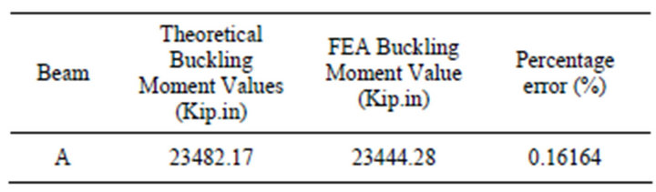
Table 3. FEA and closed form solutions for buckling for Case 3.
6. Conclusion
FE model developed in this work showed the relevance of FE in the buckling limit loads for field fabricated spherical pressure vessels beam-column supports. It gives a design engineer an insight into proper selection of beam-column supports for spherical pressure vessels. Once the number of leg support requirement is met and load per leg is known; optimum leg can be designed and sized using the software developed in this research work.
REFERENCES
- R. R. Erin, “Elastic Flexural-Torsional Buckling Analysis Using Finite Element Method and Object-Oriented Technology with C/C++,” Master’s Thesis, University of Pittsburgh, Pittsburgh, 2002.
- N. S. Trahair, “Flexural Torsional Buckling of Structures,” CRC Press, Boca Raton, 1993.
- W. F. Chen and E. M. Lui, “Structural Stability Theory and Implementation,” Prentice-Hall, Upper Saddle River, 1987.
- A. Javidinejad, “Buckling of Beams and Columns under combined Axial and Horizontal Loading with various Axial Loading Application Locations,” Journal of Theoretical and Applied Mechanics, Vol. 42, No. 4, 2012, pp. 19-30.
- N. S. Trahair and K. J. R. Rasmussen, “Finite Element Analysis of the Flexural Buckling of Columns with Oblique Restrains,” Research Report No. R835, The University of Sydney, Sydney, 2006. http://www.civil.usyd.edu.au
- F. Mohria, C. Bouzerira and M. Potier-Ferry, “Lateral Buckling of Thin-Walled Beam-Column Elements under Combined Axial and Bending Loads,” Thin-Walled Structures, Vol. 46, No. 3, 2008, pp. 290-302. doi:10.1016/j.tws.2007.07.017
- L. Graham-Brady, B. W. Schafer and J. Li, “Analysis of Post-Buckling Behaviour of Beam-Column Structures via Stochastic Finite Elements,” 16th ASCE Engineering Mechanics Conference, Seattle, 16-18 July 2003.
- P. N. Jiki, “Stability of Matrices for Lateral Buckling Analysis of Beams,” Nigerian Journal of Technology, Vol. 25, No. 1, 2006, pp. 36-43.
- Y. L. Pi and N. S. Trahair, “Prebuckling Deflections and Lateral Buckling II: Applications,” Journal of Structural Engineering, Vol. 118, No. 11, 1992, pp. 2967-2986. doi:10.1061/(ASCE)0733-9445(1992)118:11(2967)
- Z. Yuan, “Advanced Analysis of Steel Frame Structures Subjected to Lateral Torsional Buckling Effects,” Doctor’s Thesis, Queensland University of Technology, Brisbane, 2004.