Engineering
Vol. 4 No. 1 (2012) , Article ID: 17094 , 7 pages DOI:10.4236/eng.2012.41003
The Empirical Prediction of Gas Dispersion Parameters on Mechanical Flotation Cells
1Mining Engineering Department, Science and Research Branch, Islamic Azad University, Tehran, Iran
2Mining Engineering Department, Amirkabir University of Technology, Tehran, Iran
3Mining Engineering Department, Tarbiat Modares University, Tehran, Iran
4Mining Engineering Department, University of Tehran, Tehran, Iran
Email: *brezai1@yahoo.com
Received March 4, 2011; revised April 11, 2011; accepted April 20, 2011
Keywords: Gas Dispersion; Input Power; Empirical Estimation and Flotation
ABSTRACT
Gas dispersion properties include bubble size ( ), gas holdup (
 ) and bubble surface area flux (
 ) and input power (
 ) are effective parameters on flotation performance. During the last 10 years, some investigations have been carried out to measure these parameters in mechanical flotation cells. In this research, some models are created to estimate gas dispersion properties and input power by experimental data. Variables of models are impeller peripheral speed (
 ), superficial gas velocity (
 ) and pulp density (
 ) and final form of models are
 ,
,  ,
,  and
and 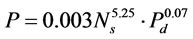 . According to these equations, most effective variables are QUOTE
  ,
,  and
and  , respectively.
1. Introduction
Physiochemical aggressions of reinforced concrete strucSeparation by flotation is a result of interaction of many variables, usually involving chemical, operational and machine factors. Machine factors such as impeller speed, air flow rate and cell design do not affect the process performance in isolation, but when combined they create the hydrodynamic conditions governing that performance [1]. Gas dispersion is a key machine factor in the mineral flotation process. Many attempts to relate Gas dispersion properties include bubble size ( ), superficial gas velocity (
 ), gas holdup (
 ) and bubble surface area flux (
 ) to flotation performance have been made.
The first-order flotation rate constant (k) is given by 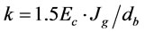 where
where  is the collection efficiency. The relationship can be rewritten in terms of bubble surface area flux, namely
 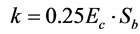 [2]. Bubble surface area flux
  is a good measure of the gas dispersion in a flotation cell.
  is a property of the gas dispersed phase in a flotation cell which combines the effect of bubble size
  and superficial gas velocity
  . Some authors have investigated the effect of gas dispersion properties on the flotation rate constant in plant and pilot scale mechanical cells over a range of operating conditions for four impeller types. They found that the rate constant was not readily related to bubble size, gas holdup or superficial gas rate individually, but was related to bubble surface area flux. For example, for shallow froths the relationship was linear (
 ) where a summarized the operational and chemical factors [3-6].
In this study, input power (P, W), bubble size ( µm), gas holdup (
 , %) and bubble surface area flux (
 , s–1) were estimated in a laboratory flotation cell. Impeller peripheral speed (
 , m·s–1), superficial gas velocity (
 , cm·s–1) and pulp density (
 , %) were selected for estimating gas dispersion parameters and input power. It is thought useful to develop empirical models to estimate gas dispersion factors in different conditions due to poor understanding of gas dispersion phenomena and difficulty in measuring them in flotation cells. Also, these models could be used readily for applications such as cell comparison and selection, new cell installation, scale-up for plant design, cell optimization, circuit modeling, simulation, etc.
2. Materials and Methods
Bubble size distribution and gas holdup were measured in a laboratory Denver flotation cell. The frother was methyl iso-butyl carbinol (MIBC) with a concentration of 22.4 ppm and  (CCC, critical coalescence concentration). Quartz sample with solid density of 2.65 g/cm3 and particle size of –500 micrometers was used in flotation experiments. Impeller diameter was 0.07 meter for a cell with square section of 0.13 and height of 0.12 meter and impeller diameter was 0.09 meter for a cell with square section of 0.16 and height of 0.20 meter. The type of impeller was a Rushton turbine with 8 paddles and a stator was used around the rotor. All experiments were carried out without any baffling in the flotation cell.
The bubble size distribution and rise velocity were measured in a device similar to the McGill bubble viewer [7]. According to Figure 1, it consisted of a sampling tube attached to a viewing chamber with a window inclined 15˚ from vertical. The closed assembly was filled with water of a similar nature to that in the flotation cell (to limit changes in bubble environment during sampling) and the tube was immersed in the desired location below the froth. Bubbles rose into the viewing chamber and were imaged by a digital video camera as they slid up the inclined window, which was illuminated from behind. In this research, at first, frother was added to the water of the cell and then the viewing chamber was filled with water of the cell to prevent bubble coalescence.
The gas holdup is a variable that affects the flotation performance. The gas holdup was measured similar to Gorain (1995) [4]. For calculating net power consumption, at first equipment power consumption was measured by wattmeter in absent of pulp, then flotation cell was filled by pulp and power consumption was measured again. Net power consumption was calculated by subtracting these two measured powers.
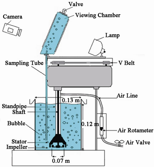
Figure 1. Bubble diameter measurement for different impeller speeds and air flow rates.
3. Theory
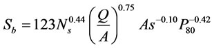
An empirical model has been developed (Equation (1)) to predict  in mechanical flotation cells using data obtained from extensive test work in Tasmania and Western Australia using different commercially available impellers in a 3 m3 flotation cell [8].
 (1)
(1)
 (2)
(2)
 (3)
(3)
In which  is impeller peripheral speed,
  is air flow rate per unit cell cross-sectional area, As is impeller aspect ratio and
  is 80% passing feed size.
The importance of bubble size in flotation cells has been appreciated since the very early days of froth flotation, when noted that “it is essential that the air should be completely atomized in the pulp and not allowed to be distributed through the pulp in the form of comparatively large bubbles [9]”. Since then, many experimental and theoretical investigations into the effect of bubble size on particle flotation have been carried out [3]. In a mechanical flotation cell, the size of the bubbles generated depends on the impeller diameter, impeller speed and air flow rate. In general, the mean bubble size decreases with increasing impeller speed and increases with increasing air flow rate [10,11].
The manner in which the mean bubble size changes, depends on the air dispersion capability of the impeller. Previous investigation also showed that pulp density affects the rheological properties of pulp in the cell and, hence, the bubble size [12]. Since  and
and  in a cell depend on bubble size, it is expected that they will also depend on impeller speed, air flow rate and pulp density of the feed to the cell.
Authors have found a linear relationship between the flotation rate constant and the power intensity for the flotation of quartz in a stirred tank agitated by a Rushton turbine impeller [13]. Specially, power intensity is very important for the flotation of coarse particles because of the high probability of bubble-particle detachment. In order to increase flotation response of coarse particles, they must be dispersed in flotation cell with minimum input energy.
It is interesting to note how poorly the flotation rate correlates with bubble size and how this correlation improves on going from bubble size to gas holdup and superficial gas velocity. However, it is not unexpected that bubble size on its own would not significantly correlate with k. Somehow the amount or volume of air in the cell should also come into the picture. That is, one would expect the flotation rate to increase on going from one to several million bubbles (of the same size) per unit volume [6].
In this study, gas dispersion parameters are estimated in a laboratory flotation cell. Impeller peripheral speed ( ) instead of impeller speed (
 ) was used to determine the contemporary influence of impeller speed and impeller diameter in models. Also, superficial gas velocity (
 ) instead of air flow rate per unit cell cross-sectional area (
 ) was used for modeling.
In a mechanical flotation cell, the input power and gas dispersion parameters may be assumed to be dependent on impeller peripheral speed ( ), superficial gas velocity (
 ) and pulp density (
 ). Different forms of multiple regression models (exponential, linear, polynomial and power) were examined by comparing their statistical significance using coefficient of multiple determination (
 ). The form of the model which most adequately represented the relationship between
  ,
,  ,
,  and
and  and the independent variables
  ,
,  and
and  have presented below:
 (4)
(4)
 (5)
(5)
 (6)
(6)
 (7)
(7)
where k, a, b, c &  are the parameters of the model.
4. Results
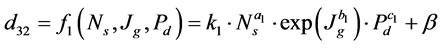
In this investigation, at first, the cell was fitted in turn with different impeller diameters commonly used in laboratory flotation cells and operated at various combinations of air flow rate and impeller speed. Then, bubble diameter was measured for the laboratory flotation cell. The mean bubble diameter adopted was the Sauter diameter, as calculated by Equation (8):
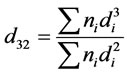 (8)
(8)
The model expressed by Equation (4) was fitted to the experimental data from the investigations at flotation cell. The parameters of  ,
,  ,
,  ,
,  and
and  were estimated using the experimental values of variables
  ,
,  ,
,  and
and  obtained in this research. Figure 2 shows a plot of the predicted values of
  from the model versus the experimentally observed values of
  . The final form of the model is shown below:
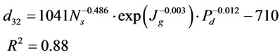 (9)
(9)
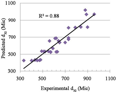
Figure 2. Experimental  versus Predicted
  obtained by Equation (9).
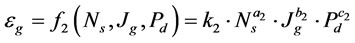
Gas holdup was modeled according to Equation (5). Figure 4 shows a plot of the predicted values of  from the model versus the experimentally observed values of
  . So, the following Equationuation is the final form of the gas holdup model

 (10)
(10)
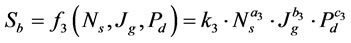
Calculating  in flotation cells is difficult and expensive due to difficulty in measuring bubble diameter. In this research, an empirical model is obtained for estimating
  in different operating conditions. So, in this investigation the Equation (6) was used for
  prediction. Figure 6 shows a plot of the predicted values of
  from the model versus the experimentally observed values of
  . The final form of the model is according to below equation:

 (11)
(11)
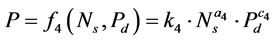
The model expressed by Equation (7) was fitted to the experimental data from the investigations at flotation cell. Figure 8 shows a plot of the predicted values of  from the model versus the experimentally observed values of
  . The final form of the model is according to below equation:

 (12)
(12)
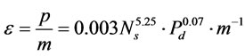 (13)
(13)
in which  and
and  are power intensity and liquid mass, respectively.
5. Discussion
The most effective parameter on bubble diameter is  and the effect of other parameters can be neglected. For
  m/s,
m/s,  cm/s and
 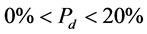 bubble diameter was obtained
  µm. Effect of impeller peripheral speed (m·s–1) and pulp density (%) on
  (µm) has been shown in Figure 3.
The most effective parameter on gas holdup is  and the effect of
  is insignificant. For
  m/s,
m/s,  cm/s and
  , gas holdup was obtained
  . Figure 5 shows the effect of impeller peripheral speed (m·s–1) and superficial gas velocity (cm·s–1) on
  (%).
(%).
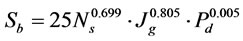
The most effective parameters on bubble surface area flux are  and
and  respectively. The effect of
  on bubble surface area flux is very low. For
 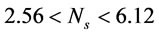 m/s,
m/s,  cm/s and
  the bubble surface area flux is obtained
  s–1 for laboratory flotation cells but this model can predict upper values of
  , too. Figure 7 shows the effect of impeller peripheral speed (m·s–1) and superficial gas velocity (cm·s–1) on
  (s–1).
The most effective parameters on input power is  and the effect of
  on input power is very low. For
Figure 3. Effect of impeller peripheral speed and pulp density on  .
.
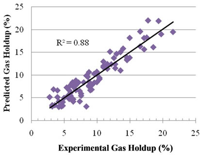
Figure 4. Experimental  versus Predicted
  obtained by Equation (10).
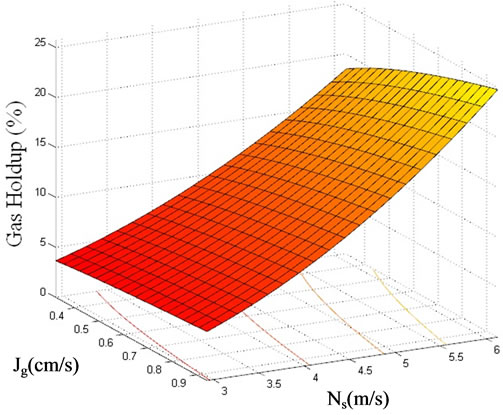
Figure 5. Effect of impeller peripheral speed and superficial gas velocity on  .
.

Figure 6. Experimental  versus Predicted
  obtained by Equation (11).
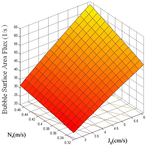
Figure 7. Effect of impeller peripheral speed and superficial gas velocity on  .
.
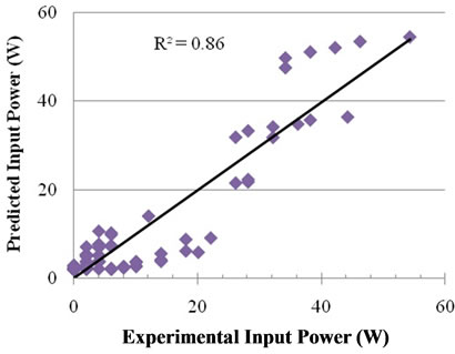
Figure 8. Experimental P versus Predicted P obtained by Equation (12).
 m/sec and
  input power was obtained
  W. Figure 9 shows effect of impeller peripheral speed (m·s–1) and pulp density (%) on
  (W). In mechanical flotation cells, power intensity of 1 to 2 kw/m3 is common [14]. Thus, according to Equation (13), an impeller peripheral speed of
  m/s (impeller diameter of 0.07 m and impeller speed of 800 to 1000 rpm) is suitable for the laboratory flotation experiments.
Regression Statistics, ANOVA and Significance of Coefficients have been given in Tables 1-3, respectively.
6. Conclusions
In this study, input power (P, W), bubble size ( , µm), gas holdup (
 , %) and bubble surface area flux (
 , s–1) were estimated in a laboratory flotation cell and the following equations were obtained:
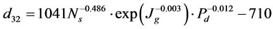
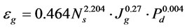


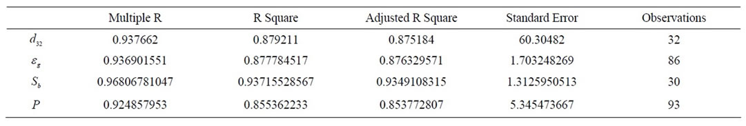
Table 1. Regression statistics.
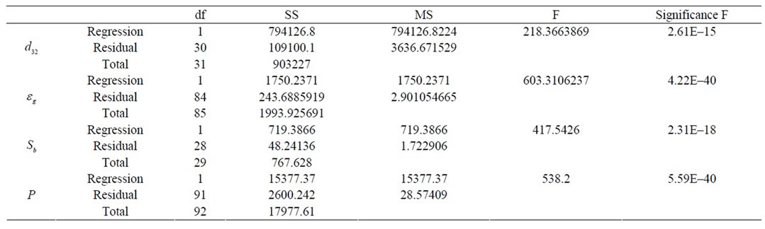
Table 2. ANOVA.
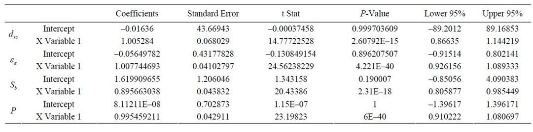
Table 3. Significance of coefficients.
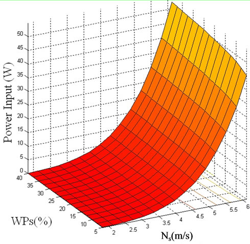
Figure 9. Effect of impeller peripheral speed and pulp density on P(W).
REFERENCES
- J. A. Finch, J. Xiao, C. Hardie and C. O. Gomez, “Gas Dispersion Properties: Bubble Surface Area Flux and Gas Holdup,” Minerals Engineering, Vol. 13, No. 4, 2000, pp. 365-372. doi:10.1016/S0892-6875(00)00019-4
- G. J. Jameson, S. Narn and M. Young, “Physical Factors Affecting Recovery Rates in Flotation,” Mineral Science Engineering, Vol. 9, No. 3, 1977, pp. 103-118.
- B. K. Gorain, J. P. Franzidis and E. V. Manlapig, “Studies on Impeller Type, Impeller Speed and Air Flow Rate in an Industrial Scale Flotation Cell. Part 1: Effect on Bubble Size Distribution,” Minerals Engineering, Vol. 8, No. 6, 1995, pp. 615-635. doi:10.1016/0892-6875(95)00025-L
- B. K. Gorain, J. P. Franzidis and E. V. Manlapig, “Studies on Impeller Type, Impeller Speed and Air Flow Rate in an Industrial Scale Flotation Cell. Part 2: Effect on Gas Holdup,” Minerals Engineering, Vol. 8, No. 12, 1995, pp. 1557-1570. doi:10.1016/0892-6875(95)00118-2
- B. K. Gorain, J. P. Franzidis and E. V. Manlapig, “Studies on Impeller Type, Impeller Speed and Air Flow Rate in an Industrial Scale Flotation Cell. Part 3: Effect on Superficial Gas Velocity,” Minerals Engineering, Vol. 9, No. 6, 1996, pp. 639-654. doi:10.1016/0892-6875(96)00052-0
- B. K. Gorain, J. P. Franzidis and E. V. Manlapig, “Studies on Impeller Type, Impeller Speed and Air Flow Rate in an Industrial: Scale Flotation Cell. Part 4: Effect of Bubble Surface Area Flux on Flotation Kinetics,” Minerals Engineering, Vol. 10, No. 4, 1997, pp. 367-379. doi:10.1016/S0892-6875(97)00014-9
- E. H. Girgin, S. Do, C. O. Gomez and J. A. Finch, “Bubble Size as a Function of Impeller Speed in a Self-Aeration Laboratory Flotation Cell,” Minerals Engineering, Vol. 19, No. 2, 2006, pp. 201-203. doi:10.1016/j.mineng.2005.09.002
- B. K. Gorain, J. P. Franzidis and E. V. Manlapig, “The Empirical Prediction of Bubble Surface Area Flux in Mechanical Flotation Cells from Cell Design and Operating Data,” Minerals Engineering, Vol. 12, No. 3, 1999, pp. 309-322. doi:10.1016/S0892-6875(99)00008-4
- R. D. Nevett, “Some Controlling Factors in Flotation,” Proceedings—Australasian Institute of Mining and Metallurgy, Vol. 37, No. 37, 1920, pp. 55-72.
- B. Shahbazi, B. Rezai and S. M. Javad Koleini, “The Effect of Hydrodynamic Parameters on Probability of Bubble-Particle Collision and Attachment,” Minerals Engineering, Vol. 22, No. 1, 2009, pp. 57-63. doi:10.1016/j.mineng.2008.03.013
- B. Shahbazi, B. Rezai and S. M. Javad Koleini, “Bubble-Particle Collision and Attachment Probability on Fine Particles Flotation,” Chemical Engineering and Processing, Vol. 49, No. 6, 2010, pp. 622-627. doi:10.1016/j.cep.2010.04.009
- C. T. O’Connor, E. W. Randall and C. M. Goodall, “Measurement of the Effects of Physical and Chemical Variables on Bubble Size,” International Journal of Mineral Processing, Vol. 28, No. 1-2, 1990, pp. 139-149. doi:10.1016/0301-7516(90)90032-T
- R. Newell and S. Grano, “Hydrodynamics and Scale-Up in Rushton Turbine Flotation Cells: Part 2. Flotation Scale-Up for Laboratory and Pilot Cells,” International Journal of Mineral Processing, Vol. 81, No. 2, 2006, pp. 65-78.
- D. A. Deglon, “The Effect of Agitation on the Flotation of Platinum Ores,” Minerals Engineering, Vol. 18, No. 8, 2005, pp. 839-844. doi:10.1016/j.mineng.2005.01.024
Nomenclature
A: Cell cross-sectional area
CCC: Critical coalescence concentration
 : Bubble Sauter diameter
 : Collection efficiency
 : Superficial gas velocity
 : Impeller peripheral speed
P: Input power
 : 80% passing feed size
Q: Air flow rate
 : Bubble surface area flux
 : Pulp density
 : Power intensity
 : Gas holdup
NOTES
*Corresponding author.