Engineering
Vol. 4 No. 3 (2012) , Article ID: 18331 , 9 pages DOI:10.4236/eng.2012.43019
Mathematical Model to Locate Interference of Blast Waves from Multi-Hole Blasting Rounds
Blasting Department, Central Institute of Mining & Fuel Research, CSIR, Dhanbad, India
Email: sujitkm@yahoo.com
Received February 8, 2012; revised March 14, 2012; accepted March 25, 2012
Keywords: Blast Waves; P-Wave Velocity; Cooperation of Blast Waves
ABSTRACT
Maximum charge per delay in a blasting round is universally accepted as the influencing parameter to quantify magnitude of vibration for any distance of concern. However, for any blasting round experimental data reveals that for same charge per delay magnitude of vibration varies with total charge. Considering linear transmission of blast waves, the paper firstly investigates into the influence of explosive weight, blast design parameters and geology of strata on magnitude and characteristics of vibration parameters and thereafter communicates that possibly interference of blast waves generated from same and different holes of a blasting round result into variation in vibration magnitude. The paper lastly developed a mathematical model to evaluate points of interference of blast waves generated from singleand multi-hole blasting round.
1. Introduction
Energy used for ground vibration is about 7% of the quantity generated in the form heat of explosion [1-4]. Detonation of explosive generates both acceptable and non-acceptable consequences. The non-acceptable consequences of blasting viz., magnitude of vibration, audible and in-audible air concussion, excessive throw and dust and fumes causes uncomfortable and unhygienic condition around the mining area. The increased environmental awareness and regular public complaints in the recent years have evolved into legislation to limit maximum magnitude of vibration for safety of structures around the mining sites [5-9]. Empirical, analytical and numerical predictor techniques have been developed to determine vibration magnitude for any distance of concern [10-13]. All the predictor Equations have considered maximum charge per delay as the main parameter for derivation of empirical Equation. The work of recent researchers’ states that charge per delay cannot be the only single parameter to quantify magnitude of vibration [14-18]. Charge weight scaling model introduced sliding time window over which the scaled charge weight should be added for determination of maximum charge weight per delay in a blasting round. Authors also used a Dynamic Finite Element Model for single blast hole to evaluate vibration as a function of VOD of explosive [19]. The author used the Seed Waveform Model to define the wave propagation characteristics. Various authors have also worked upon blast wave characteristics for prediction of vibration magnitude for any distance of concern [20,21].
Review of vibration data monitored at various sites for different distances of concern illustrates that VOD of explosive, time interval between detonation of different delays in same or different holes of a blasting round and propagating velocity in transmitting medium quantifies magnitude of vibration at a distance of concern. Since, duration of vibration for elemental charge depends upon charge quantity detonated in unit time, borehole pressure and linear charge concentration viz., density and diameter of explosive, the paper have attempted for segmental analysis of explosive length to illustrate the vibration propagation. Since, most of the seismographs record vibration at every 0.001 seconds time interval, the theoretical model evaluates propagation characteristics for infinitesimal explosive length detonated in every 1 milliseconds i.e., segmental analyses of explosive column for every blast hole and all holes in a blasting round. The paper uses linear super-imposition concept to evaluate theoretical model for determination of points of interferences during its transmission.
2. Wave Behaviour
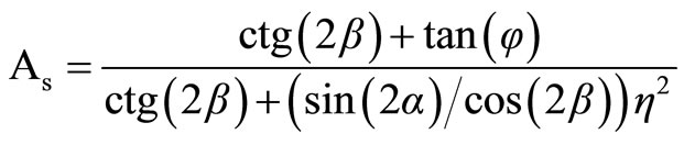
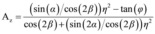
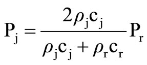
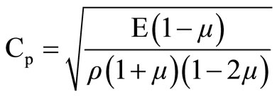
Propagation characteristics of blast waves vary according to the characteristic properties of rock strata and angle of incident of stress wave on joint plane. The quantum of energy absorbed, reflected or refracted depends upon thickness of each stratum, smoothness of joint plane and filling material within joints. At the point of incidence, the angle of incident (i) will be equal to the angle of reflection (r) and ratio between the angle of incident and refracted wave (refr) will depend upon ratio of densities and P-wave velocities of two mediums. Transmission of blast induced stress wave being a function of Poisson’s ratio, m, friction angle, f, and orientation of structural plane, b, with respect to incidence of stress wave, the magnitudes of transmitted and reflected wave can be determined with the help of transmission coefficient (As) and the reflection coefficient (Az) of P-wave, Equation 1 and 2 respectively. The pressure reduction of transmitted wave during its transmission can be determined with the help of Equation 3 [22]. The velocity of P-wave and Swave viz., Cp and Cs in rock medium can be determined with the help of Equations (4) and (5) respectively [23].
 (1)
(1)
 (2)
(2)
 (3)
(3)
 (4)
(4)
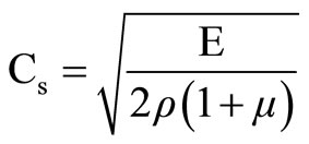 (5)
(5)
whereE = Young’s modulus;
r = Density; and
µ = Poisson ratio of rock.
3. Vibration Analysis
3.1. Experimental Evaluation
According to conservation of energy, explosive energy on detonation results into equal and opposite reaction. The effective reaction for any blasting are heat, temperature, light, sound, fragmentation, throw and vibration. The undesirable or non-acceptable forms are noise/air overpressure, vibration and excessive throw, if any, causing structural and human damage. For same charge per delay and varied total charge variation in vibration magnitude illustrates the characteristics of cooperation of explosive weight detonated in same and different delays of a blasting round (Tables 1 and 2). In Table 1 for same charge per delay and varying total charge, the magnitude of vibration increases with increase in total charge (Sl. Nos. 1 and 2; Sl. Nos. 7 and 8). However, with an increase in depth of blasthole and charge per hole (Sl. No. 3 and 4), the magnitude of vibration is less in comparison to earlier, indicating loss of energy during its transmission through the rock medium. Similarly, comparison between blast nos. 3 and 6 illustrates that initiation with detonating cord results into more vibration. High VOD detonating cord, approx. 6500 ms–1, results into instantaneous initiation of total charge within a blasthole, resulting into minimum probability of interference of blast waves generated from different sections/segments of a blasthole. Similarly, comparison of single-hole blasts listed in Table 2 (sl. Nos. 1-3) it is observed that magnitude of acceleration increases with maximum charge per hole. Similarly, an increased magnitude of acceleration

Table 1. Details of charge parameters and blast-induced vibration for varied charge parameters.
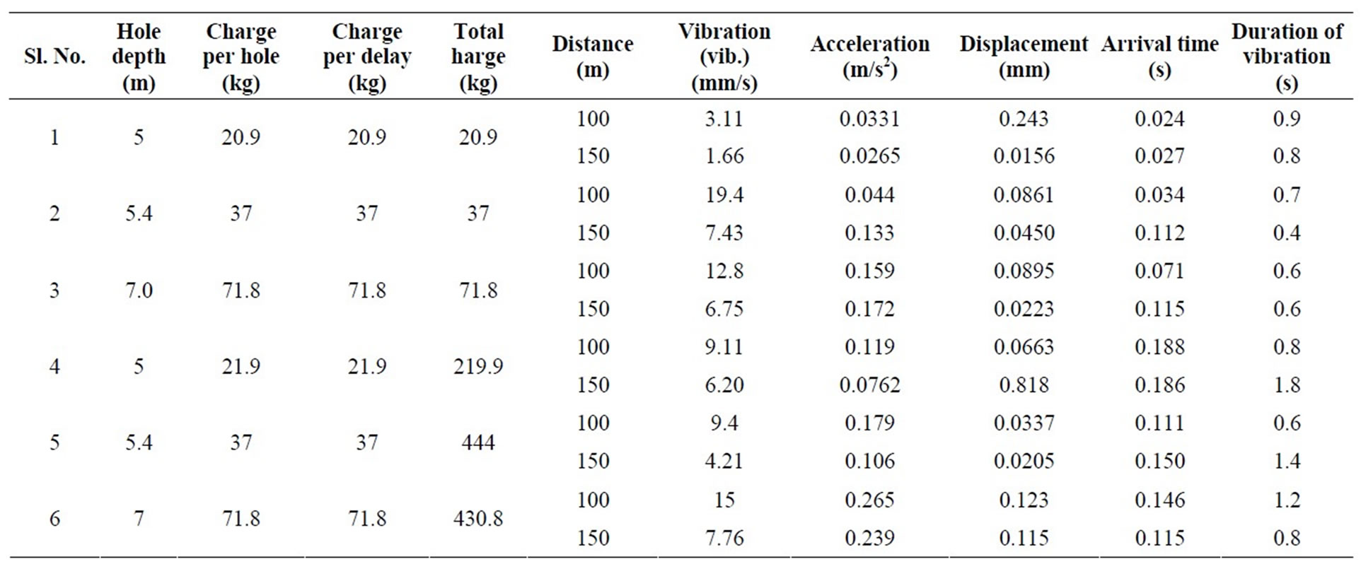
Table 2. Variation in vibration parameters with change in charge parameters.
with an increase in distance of measurement indicates cooperation of blast wave (Sl. Nos. 2 & 3). However, magnitude of displacement decreases possibly due to reduction in its energy component. Similarly, comparing the vibration parameters for multi-hole firing it is observed that acceleration decreases with an increase in distance of measurement (Sl. Nos. 4-7, Table 2). But, the magnitude of displacement computed by the seismographs indicates no certain characteristics, indicating the influence of interference of blast waves generated from different blast holes. Comparing magnitude of acceleration between singleand multi-hole blasts indicates that magnitude of acceleration is always higher with an increase in total charge. In comparison to single-hole blasts, magnitude of displacement for multi-hole blasts, except for Sl. No. 6, is observed to have less magnitude, indicating loss of energy during its transmission. Comparing the arrival time of blast waves between singleand multihole firing it is observed that the arrival time is always higher for multi-hole shots, indicating interference of blast waves during their transmission. Therefore, attenuation of vibration magnitude i.e., vibration propagation varies with linear charge concentration, charge length, diameter of explosive and VOD of explosive. Similarly, for same charge per delay, magnitude of vibration measured at same place may also vary with distribution characteristics of explosive weight in blast holes.
3.2. Theoretical Evaluation
Propagation velocity and intensity of stress generated due to detonation of explosive varies with energy contained in it during the time of detonation. Velocity and intensity of wave varies with rate of energy loss due to absorption in the preceding medium/layer. Energy loss being proportional to energy contained, loss of energy will be more at initial period (closer distance) than that observed at far off distances i.e., attenuation of vibration magnitude will be faster at closer distance than that observed at far off distances. At closer distance, interference of blast waves is influenced by enhanced charge length/concentration, ratio between total charge and charge per delay and delay timing between two initiations made in same or different holes of a blasting round. Interference of blast waves from different holes result into constructive or destructtive interference i.e., magnification or reduction in resultant magnitude. Constructive interference causes amplification in magnitude and sustains for longer duration. Destructive interference, on the other hand, results into low magnitude and sustains for lesser time duration. For far off distances, magnitude of vibration measured is the resultant impact of interference of blast waves generated from different delays of a blasting round. Attenuation characteristics in this zone are also very slow. At such distances, wave transmitted from different holes of a blasting round adds to the less energy contained waves during the path of transmission to quantify duration and magnitude of vibration. The waves at such distances take longer time to pass through any element of construction (civil or rock) or particle of medium coming in its path and generates poor stress and strain rate.
Based on variation in measured vibration data, the paper attempted to evolve a theoretical model to understand the philosophy of interference of blast waves from single blast hole for both monolithic and bedded strata (Figures 1 and 2). Considering the concept of propagation of waves through bedded strata, the paper evolved a mathematical model for an array of holes in a blasting round. For computer simulation, arbitrary point, (X, Y, Z), in the transmitting medium has been considered as the point of interference. For ease in calculation, the paper assumed

Figure 1. Schematic diagram of blast hole in monolithic rock mass.

Figure 2. Schematic diagram showing blast hole in horizontal bedded strara.
the coordinate of bottom of first hole initiated in a blasting round as (0, 0, 0), Figure 3.
3.2.1. Single-Hole Blast in Monolithic Rock
Let Velocity of detonation of explosive = Ve ms–1;
Sonic velocity of transmitting medium = Vm ms–1;
Depth of hole = h, m;
Distance of sensor = h1, m;
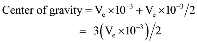
At 0.001 seconds length of explosive column detonated = Ve × 10–3 m;
Center of gravity of explosive detonated in 0.001 seconds = (Ve × 10–3)/2;
 (6a)
(6a)
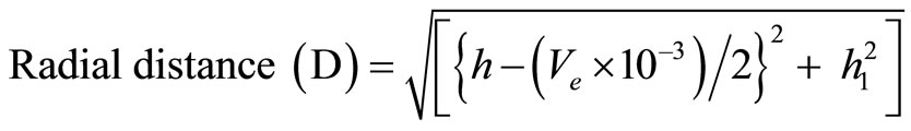
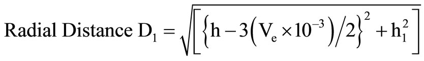
Similarly, for next sector, center of gravity and corresponding radial distance to the sensor can be determined from Equations (6b) and (6c) respectively.
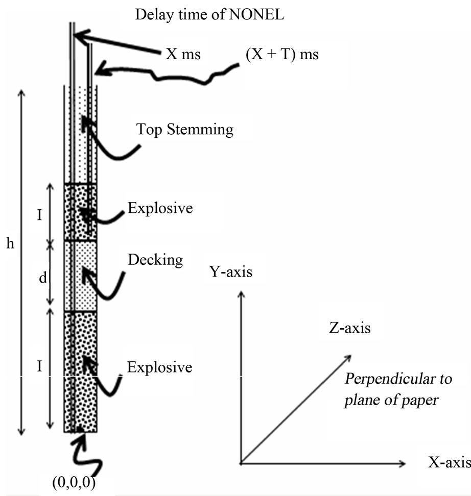
Figure 3 Schematic diagram of blasthole loaded in two decks.
 (6b)
(6b)
 (6c)
(6c)
Therefore, the general form of Equation to determine center of gravity from bottom of blast hole for each sector and the corresponding radial distance to the sensor can be determined with the help of Equations (6d) and (6e) respectively.
 (6d)
(6d)
 (6e)
(6e)
If q(n) is the angle between the horizontal plane and line of propagation of blast wave generated from sector “n”, then
 (6f)
(6f)
where n is the term or section of explosive detonated from bottom of the hole.
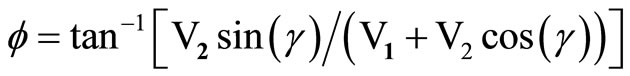
Interference of propagating blast waves will depend upon cumulative impact of explosive column detonated in each sector i.e., detonation velocity of explosive column, sonic velocity of transmitting medium, delay in detonation timings for each sector and phase difference between them. The resultant impact due to collision of waves detonated from two sectors will be of the form as shown in Figure 4 Magnitude and direction of resultant can be evaluated with the help of Equations (7a) and (7b) respectively.
Considering magnitude of vibration generated by two sectors as V1 and V2 with phase angle, g, the resultant impact of first two sectors i.e., R and f will be the input parameter to determine the second resultant when the sensor is struck by blast wave detonated from third sector. The process will continue till all sectors along the length of hole are detonated. The waves generated from each sector will also suffer reflection and refraction when interfered by any fracture or joint plane and therefore the distance between the source and measuring location (sensor) will vary for each sector. The cumulative distance impact for total charge length can be determined with the help of Equation (7c). Considering USBM empirical Equation as best-fit predictor Equation, the magnitude of vibration measured at any place due to the impact of total charge length can be determined with the help of Equation (7d). Here the resultant impact from first two sectors will be input parameter when the sensor is struck by wave generated from third sector and the process will continue till total charge length under consideration is evaluated. Here, instead of charge per delay, Q, (kg), the paper considered “Q” as the quantity of explosive (kg) detonated in 1 millisecond. For monolithic rock mass and close field monitoring, probability of interference will be minimized. However, for longer distance of measurement, constructive or destructive superimposition of waves may take place during the path of travel.
 (7a)
(7a)
 (7b)
(7b)

or
 (7c)
(7c)
 (7d)
(7d)
whereQ = rπr2Ve × 0.001; and r = radius of blasthole (m);
r = density of explosive (kg/m3).
The mathematical model to locate interference of blast waves generated from two sectors of same blast hole is given below:
Suppose,
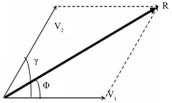
Figure 4. Schematic diagram showing the resulatant impact due to detonation of two sectors.
Time of detonation of an explosive sector (S1) = T seconds;
Detonation time of explosive sector (S2) causing interference with sector S1 = T1 seconds;
Time difference between initiation of two sectors = T – T1 seconds;
Assuming time of interference = T2 seconds.
Distance traveled up to the point of interference on detonation of sector S1 will be
 (8a)
(8a)
Distance traveled up to the point of interference on detonation of sector S2 will be
 (8b)
(8b)
Equating above two Equations, we have
 (8c)
(8c)
Therefore, knowing the sonic velocity of rock medium (Vm) and time of detonation of both the sectors viz., T and T1, location of interference from two sectors, if any, can be identified/determined by the method of iteration. Since, a number of interference points can be identified, the same can be evaluated by computer simulation method.
3.2.2. Single-Hole Blast in Bedded Strata
For bedded strata, depending upon rock mass characteristics, blast hole may be loaded in singleor multi-deck systems. Figure 4 shows schematic diagram of a blast hole loaded in multi-decks. Initiation of holes may be carried out by either detonating cord or NONEL system. Similarly, Figure 3 shows two-deck charging with NONEL system of initiation. With detonating cord system of initiation i.e., top initiation, the primer or booster is first detonated to trigger or detonate the column explosive in each deck. Therefore, it can be well understood that due to more number of strata for lower decked explosive column and delayed time of initiation for lower decks there will be minimum possibility of interference of blast waves generated from two different decks. However, when soft stratum is overlain by hard strata the probability of interference of blast waves generated from different decks cannot be ignored. For NONEL system of initiation i.e., bottom initiation, probability of interference of blast waves generated from different decks may take place. Probability of interference of blast waves generated from different decks of same blast hole is minimum when compact hard strata lies above loose strata. However, for vice-versa strata condition i.e., soft layer overlying the hard strata, probability of interference of waves at any distance of concern cannot be ignored.
In Figure 4 the sensor is located at a horizontal distance h1 from center of blast hole of depth h. The path of travel by blast waves from individual sector and each deck are shown by dotted lines viz., AS1, BS1 and CS1. The path of travel through bedded strata will always suffer refraction when transmitted through different mediums and actual distance of travel will always be more than the actual linear length. The angle of refraction will depend upon characteristics of two consecutive transmitting mediums. Energy absorbed in each layer will also be different and directly proportional to magnitude of energy contained in it.
Let Detonation time for bottom deck = t;
Detonation time for next above deck = t1;
Length of explosive column for bottom deck = l;
Length of explosive column for upper deck = l1;
Length of non-explosive material between two decks = d;
VOD of explosive = Ve m/s;
Average P-wave velocity of vibration wave generated from bottom deck = Vm m/s;
Average P-wave velocity of vibration wave generated from upper deck = Vm1 m/s;
Length of explosive column detonated in 0.001 seconds = Ve × 10–3 m;
Number of sectors of explosive detonated in bottom deck = l/(Ve × 0.001);
Number of sectors of explosive detonated in upper deck = l1/(Ve × 0.001);
Coordinate of bottom of hole = (0, 0, 0);
Coordinate for interference of two blast waves = (X, Y, Z).
For three dimension analysis Xand Y-axis are considered along the horizontal plane i.e., along length and width of blasting patch and Z-axis in vertical plane i.e., along depth of blasthole (Figure 3). The coordinate of center of gravity of bottom most and subsequent sector of explosive column in bottom deck will be (0, 0, 0.001Ve/2) and {0, 0, 0.001(Ve + Ve/2)} respectively. Similarly, for next deck of explosive column, the center of gravity for bottom most and subsequent sector will be (0, 0, (l + d + 0.001Ve/2)) and [0, 0, {l + d + 0.001(Ve + Ve/2)}] respectively. The generalized term for center of gravity for each sector for bottom and upper deck of explosive column from the base of blast hole for two deck system of charging will be of the form given in Equations (9a) and (9b) respectively.
 (9a)
(9a)
 (9b)
(9b)
wheren = sector number from the bottom of lower deck (point of initiation)
n1 = sector number from the bottom of upper deck (point of initiation)
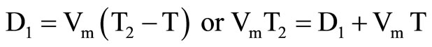
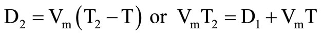
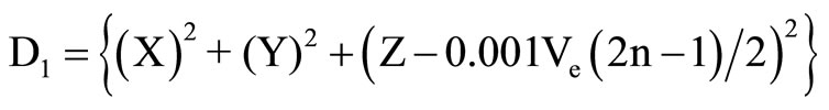
k = l + d Interference of waves take place from sectors detonated either same or different decks. Firstly, considering interference e of waves from sectors detonated in same deck. If the distance travelled by wave from different sectors of same deck to the point of interference be D and D1 respectively, the mathematical Equations for determining the magnitudes for each will be of the form as given in Equations (10a) and (10b) respectively. If time of detonation of two waves under interference are t and t1 and the time of interference is t2, then distance travelled by each wave can be determined with the help of Equations 10(c) and (10d) respectively. Equating Equations (10a)-(10d), location of interference, by the method of iteration, can be determiend from Equation (10e).
 (10a)
(10a)
 (10b)
(10b)
 (10c)
(10c)
 (10d)
(10d)
Equating Equations (10c) and (10d), we have
 (10e)
(10e)
Similarly, considering interference of waves due to detonation of explosive from different decks, the linear distance travelled by each can be determined by using Equation (11). Interfenece of blast waves will depend upon characteristics of transmitting medium and initiation timing of two sectors.
 (11a)
(11a)
 (11b)
(11b)
LetInitiation time of sector from lower deck = t1;
Initiation time of sector from upper deck = t2;
Time of interference of waves from two sectors = t3;
Time available for the sector from lower deck to travel to the point of interference = (t3 – t1);
Time available by a sector from upper deck to travel to the point of interference = (t3 – t2);
Average sonic velocity of vibration wave generated by the sector from lower deck = Vm;
Average sonic velocity of vibration wave generated by the sector from upper deck = Vm1.
Distance traveled by the first sector to the point of interference,
 (12a)
(12a)
Distance traveled by the second sector to the point of interference,
 (12b)
(12b)
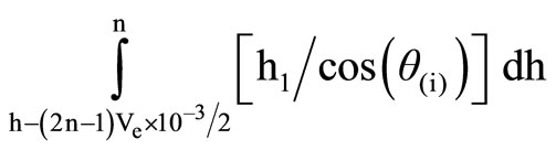
If θ(n) and β(n1) be the angles of transmitted waves with respect to horizontal plane, then the horizontal distance for each can be detrmined by using Equations (12c) and (12d) respectively.
 (12c)
(12c)
 (12d)
(12d)
whereqn = tan–1 (h – 0.001 × (2n – 1)Ve)/h1;
βn1 = tan–1 (h – k + 0.001 × (2n1 – 1)Ve)/h1;
h2 = horizontal distance between blasthole and location of interference.
Since, the horizontal distance traveled by both the sectors are same, Equations (12c) and (12d) reduces to as given in Equation (12e).
 (12e)
(12e)
Knowing sonic velocity of rock medium, time of detonation of each sector in a blast hole and time of triggereing of sensor, time taken by the blast wave to reach the location of interference can be determined by the method of iteration. Evaluation of the above Equation being cumbersome and time consuming, computer simulation technique should be adopted to evaluate and locate the point of interferences.
For monolithic rock mass with constant sonic velocity and minimum delay time between detonation of two decks i.e., 25 ms, there will be minimum possibility of interference of blast waves generated from same blasthole. However, probability of interference of blast waves cannot be ignored when length of explosive column is high for single hole blast or when more number of holes are detonated in a blasting round. Probability of interfereence is maximum for down-the-hole initiation and when soft strata is overlaying hard strata. For bedded strata, blast waves undergo refraction when transmitted from one medium to another and sonic velocity varies with strata characteristics.
3.2.3. For Array of Blastholes
For an array of blast holes in a blasting round, the coordinates of bottom or base of each hole in three-dimensional form can be represented by matrix, “A”. Here, the first element of the matrix (on top left corner) indicates the first hole initiated in the blasting round. The row and column of the matrix represents number of holes in a row and number of rows in blasting round respectively. Therefore, for “m” number of holes in a row and “n” number of rows, the matrix “A” will be of order n x m. For each row, the coordinate of bottom of each blasthole is formed by an increment of magnitude, s, where “s” indicates the spacing of blastholes in a row. Similarly, number of elements in each column of matrix represents number of rows in a blasting round, the matrix is obtained by an increment of magnitude “b”, where “b” represents burden between rows. For each blast hole the coordinates of each sector of explosive column i.e., the coordinates of “z” can be obtained in the form of a sub-matrix for each blasthole (element) within the matrix “A”. The coordinates of each sector of explosive column within the blasthole can be obtained by adding 0.001 Ve to z-axis coordinate for each element in the matrix “A”. The dimension of this matrix will depend upon depth of blasthole, charge length and VOD of explosive column. The matrix will have its elements in single column and the order of the matrix will be of order w × 1, where, “w” represents number of sectors denoted in a blast hole. Matrix “B” represents sonic velocity of transmitting medium. The dimension of matrix “B” will depend upon number of layers encountered by blast wave. Order of this matrix will be 1 × o, where “o” represents the number of layers of rock medium. Considering thickness of each strata and direction of blast wave, actual length of travel in a particular medium can be deterimed. When wave is transmitted from one medium to another, rate of energy absorbed and angle of refraction can also be determined with the help of Equations (1)-(5). Knowing the actual blasting time and triggering time of the instrument at a given location, coordinates of point of interference of waves, if any, can be detrmined by the method of iteration. An arbitary, three-dimensional coordinate, is required as an input to simulate the method of iteration technique and evaluate the locations of interference for each wave.
4. Conclusion
Wave generated from different sectors of same or different holes detonated in same or different delays of a blasting round causes constructive or destructive interference of blast waves. The characteristics of interference of blast waves i.e., phase of interaction, quantifies magnitude of vibration and its corresponding frequency at any distance of conceren. At longer distance, time duration between detonation of explosive and triggering of sensor increases and multiple interferences of blast waves take place during the path of travel. At such distances, seismographs receives the resultant impact of interference of blast waves generated from different sectors of same or different holes of a blasting round. At such distances attenuation of vibration magnitude is slow and is less. At close distance, probability of interference will be minimized due to high propagation velocity of blast waves. At such distances probability of interference is from holes detonated in separate delays and attenuation is also fast. At intermediate distance, magnitude of vibration depends upon P-wave velocity of blast waves in different transmitting rock layers, time of detonation of each delay, VOD of explosive, charge per hole and number of holes in a blasting round. Therefore, for any blasting round reduction or magnification in magnitude of vibration will, depend upon phase of interaction of each blast wave generated from different sectors.
REFERENCES
- A. Scott, G. P. Chitombo and T. Keine, “The Challenge of the Prediction and Control of Fragmentation in Mining,” The 4th International Symposium on Rock Fragmentation in Mining, Vienna, 5-8 July 1993, pp. 507-517.
- P. L. Pastika, M. Indihar and B. Von Wald, “Improved Fragmentation for Mine Cost Reduction,” The 68th Annual Minnesota Section, SME, Duuth, 24-26 January 1995, pp. 185-192.
- A. T. Spathis, “On the Energy Efficiency of Blasting,” The 4th International Symposium on Rock Fragmentation by Blasting, Johannesburg, 5-8 July 1999, pp. 81-90.
- J. A. Sanchindrian, P. Segarra and, L. M. Lopez, “Energy Components in Rock Blasting,” International Journal of Rock Mechanics & Mining Sciences, Vol. 44, No. 1, 2007, pp. 130-147. doi:10.1016/j.ijrmms.2006.05.002
- B. M. Habberjam and J. T. Whetton, “On the Relation between Seismic Amplitude and Charge of Explosive Fired in Routine Blasting Operations,” Geophysics, Vol. 17, No. 1, 1952, pp. 116-128. doi:10.1190/1.1437728
- Directorate General of Mines Safety (DGMS), “Circular Technical 7 of 1997. Directorate General of Mines Safety, India,” Government of India—Ministry of Labour & Employment, pp. 500-508.
- C. Sjoberg, B. Arson, M. Indstorm and K. Palmqvist, “A Blasting Method to Control Crack Extension and Safety Underground,” ASF Project No. 77/224, Nitro Consult, Gothenburg, 1977.
- C. Sjoberg, “Cracking Zones around Sender Borehole Charges,” Proceedings of Annual Discussion Meeting BK-79, Swedish Rock Construction Committee, Stockholm, 1979, pp. 53-98.
- D. Blair and A. Minchinton, “On the Damage Zone Surrounding a Single Blasthole,” Proceedings of the 5th International Symposium on Rock Fragmentation by Blasting, Montreal, 25-29 August 1996, pp. 121-130.
- A. Ghosh and J. K. Damen, “A Simple New Blast Predictor (Based on Wave Propagation Laws) of Ground Vibrations Induced Predictors,” The 24th US Symposium of Rock Mechanics, Texas, 20-23 June 1983, pp. 151-161.
- M. S. Siskind, J. W. Kopp and C. H. Dowding, “Structure Response and Damage Produced by Ground Vibration from Surface Mine Blasting,” Report of Investigation RI850-7, US Bureau of Mines, 1980, p. 74.
- P. P. Roy, “Prediction and Control of Ground Vibration Due to Blasting,” Colliery Guardian, Vol. 239, No. 7, 1991, pp. 215-219.
- B. Redpath and T. E. Ricketts, “An Improved Scaling Procedure for Close-In Blast Motions,” Proceedings of 13th Conference on Explore and Blasting Techniques, Miami, 5-6 February 1987, pp. 118-131.
- D. P. Blair, “Charge Weight Scaling Laws and the Superposition of Blast Vibration Waves,” Journal for Blasting and Fragmentation by Blasting, Vol. 8, No. 4, 2004, pp. 221-239.
- J. S. Rinehart, J. P. Forttin and L. Burgin, “Propagation Velocity of Longitudinal Waves in Rocks. Effects of State of Stress, Stress Level of the Waves, Water Content, Porosity, Temperature, Stratification and Texture,” Proceedings of the 4th Symposium of Rock Mechanics, University Park, 30 March-1 April 1961, pp. 119-135.
- S. K. Mandal, M. M. Singh, and N. K. Bhagat, “Magnitude of Vibration vis-à-vis Charge per Delay and Total Charge,” Journal of the Institution of Engineers (India), Vol. 86, 2007, pp. 32-37.
- A. T. Spathis, “A Scaled Charge Weight Superposition Model for Rapid Vibration Estimation,” Journal for Blasting and Fragmentation by Blasting, Vol. 10, No. 1-2, 2006, pp. 9-31.
- D. P. Blair and J. J. Jiang, “Surface Vibrations Due to a Vertical Column of Explosive,” International Journal of Rock Mechanics and Mining Sciences & Geomechanics Abstracts, Vol. 32, No. 2, 1995, pp. 149-154. doi:10.1016/0148-9062(94)00036-3
- C. K. McKenzie, C. R. Scherpenisse, J. Arriagada and J. P. Jones, “Application of Computer Assisted Modeling to Final Wall Blast Design,” Proceedings of EXPLO’95 Conference, Brisbane, 4-7 September 1995, pp. 285-292.
- A. M. Abo-Zena, “Radiation from a Finite Cylindrical Explosive Source,” Geophysics, Vol. 42, No. 7, 1977, pp. 1384-1393. doi:10.1190/1.1440799
- P. A. Heelan, “Radiation from a Cylindrical Source of Finite Length,” Geophysics, Vol. 18, No. 3, 1953, pp. 685- 696. doi:10.1190/1.1437923
- H. Kolsky, “Stress Waves in Solids,” Dover Publications Inc., New York, 1983.
- Z. Q. Guo, “Wave in Solid Objects,” Earthquake Publishing House, Beijing, 1982.