Engineering
Vol. 3 No. 4 (2011) , Article ID: 4591 , 4 pages DOI:10.4236/eng.2011.34037
Proposing a New Model of Hangers in Pedestrian Suspension Bridges to Solve Hangers Slackness Problem
1Faculty of Civil Engineering, Department of Structural Engineering, Tabriz University, Tabriz, Iran
2Faculty of Engineering, Department of Civil Engineering, Azad University of Shabestar Branch, Shabestar, Iran
E-mail: barghian@tabrizu.ac.ir, gtxhadi_1984@yahoo.com
Received December 17, 2010; revised March 3, 2011; accepted March 9, 2011
Keywords: pedestrian suspension bridge, vertical hangers, inclined hangers, modified hangers (suspenders), nonlinear static, slackness
ABSTRACT
The hangers of suspension bridges can be placed in two forms: vertical or inclined form. Inclined hangers are more liable to fatigue. Vertical hangers are subjected to greater fluctuations of stress resulting from bridge wind loads. To improve aerodynamic stability, inclined hangers can be used instead of vertical ones. Some inclined hangers show considerable signs of distress and some of them show slackness due to their location against loads. In this paper a pedestrian suspension bridge with vertical hangers has been studied as a case study. Then, the same bridge has been studied with inclined hangers. To reduce internal forces, fatigue and slackness in hangers, horizontal cables have been added to inclined hangers. This modification is proposed by the present authors. The added horizontal cables transfer the tensile load from overstressed hangers to adjacent slacked hangers. Three different hanger patterns have been analyzed under nonlinear static analysis for symmetrical and nonsymmetrical live load plus dead load. Results showed that the modified hanger system had been improved considerably in comparison with vertical or inclined hangers and wherever that there is no improvement some solutions have been proposed.
1. Introduction
Suspension bridges are among the structures that can be constructed over long spans, and due to the high accuracy, performance, computing and control system after implementation, they are safe to use [1]. Pedestrian suspension bridges have inclined or vertical hanger systems, which transfer forces from the deck to the main cables. Inclined hangers due to the damping role against dynamic and lateral loads act better than vertical ones. But inclined hangers due to slacking under excessive tension forces and also due to early fatigue—in comparison with vertical hangers—require modification in their systems to achieve optimum system. In this way the damping role is achieved and excessive tensile stresses are reduced and finally slack problems are eliminated [2]. For this reason an optimal system for inclined hangers, the modification on this system was recommended by the authors. Zyang King Wu, Takahasi and Nakamura [3] researched the possibility of cable slacking as well as displacements and internal forces in cable-stayed bridges. In another paper, Wu, Takahasi and Nakamura [4] analyzed the slackness of cables in prestressed concrete cable-stayed bridges under the strong ground motion that slacking had occurred. Also, Wu, Takahasi and Nakamura [5] investigated the effect of slacked cables on nonlinear parametric vibrations of inclined cables under their support periodic (cycle) stimulations. They considered bending rigidity and damping in equilibrium equations to solve diverging problem during slackness. Sih and Tang [6] searched the growth of crack due to fatigue in cablestayed bridges. This fatigue occurred due to overstressing and slacking of cables. The nonlinear effect of slacked cables in suspension bridges was given in the papers of Lazer and Mckenna [7], Peterson [8], Sepe and Augusti [9]. Some researchers have studied the disadvantages of inclined hangers in suspension bridges, especially Humber Bridge and Severn Bridge in England and Busphurus Bridge in Turkey. All of them are highway bridges and have inclined hangers. In those bridges, early fatigue and fracture of hangers have been observed [10]. Inclined hangers of Severn Bridge were designed for a period of 20 to 30 years. However, the existing wires in the hangers started to break eight years after the bridge opening. Connections between the deck and hangers were locally broken. Fracture was caused by fatigue due to local bending. There were some slacked and overstressed hangers due to heavy loads. The damage was originally happened by longitudinal relative movement between the main cable and deck when a change in stress in two parts of hangers had occurred. Hitherto it proposed to replace vertical hangers with inclined hangers for Severn Bridge [11]. However, the vertical system decreases the ability of a bridge to resist against fluctuations caused by wind [11].
1.1. Analytical Model
As a case study, the data of Soti Ghat bridge—a pedestrian suspension bridge in Nepal—was chosen. This bridge has a main span of 100 meters length. The cross section of the bridge deck is shown in figure 1. The height of bridge tower is 16 meters. The hangers of the bridge are vertical. First, vertical hangers were modeled. Then, the vertical hangers were replaced by inclined ones in the model. Two different systems of hangers were compared with each other. The bridges with vertical and inclined hangers are shown in Figure 2 and 3 respectively.
1.2. Proposing a New Model for Bridge Hangers
The vertical hangers have been usually used in most pedestrian suspension bridges and a few of these bridges have been built by inclined hangers. In this paper, it has attempted to present a new model to remove the defects of both vertical and inclined hangers. This model has been accomplished of inclined hangers so that the distribution of load, between two adjacent hangers is done by
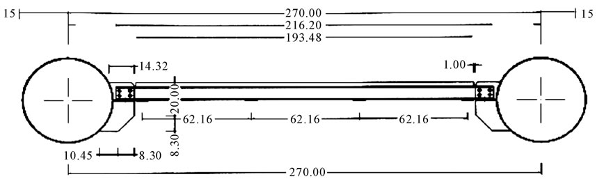
Figure 1. The cross section of the Soti Ghat Bridge.
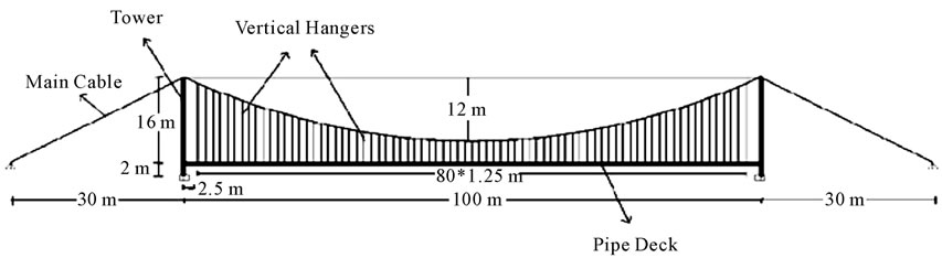
Figure 2. The pedestrian suspension bridge with vertical hangers.
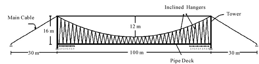
Figure 3. The pedestrian suspension bridge with inclined hangers.
a member parallel to the deck. This member will transfer the tensile load from the overstressed hanger to the adjacent slacked hanger. The proposed model is shown as the modified hangers in Figure 4.
For all members—except main cables and hangers— Young’s modulus and density were considered as 2 × 10¹¹ N/m2 and 7850 kg/m3 respectively. For main cables and hangers the fy and fu values were used as 1.18 × 10⁹ N/m2 1.57 × 10⁹ N/m2 and the density of 7850 kg/m3, where fy and fu are yield stress and tensile strength respectively. In this study nonlinear static analysis was considered.
2. Materials and Methods
Pedestrian suspension bridges usually experience several loads at the different times. These loads may be due to pedestrians, bicycles, motorcycles, animals, or due to external loads such as earthquake and wind loads [12]. In this study, the bridge was supposed to be subjected to live and dead loads statically. Live load was used symmetrically and asymmetrically as a distributed load with the amount of q as in,
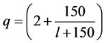 (1)
(1)
where l is the loaded length (m) and q is the intensity of load (kN/m2). The amount and patterns of loading is given in Table 1 [13]. Dead load of the bridge was calculated by the software as gravity load. The amount of pre-stressed load of cables was considered based on the weight of cables, sag and axial stiffness in cables. It was shown that the critical conditions of live loads were due to patterns A and D. The A load is symmetrical and the D load is asymmetrical.
3. Results and Discussions
The results of analyses for both vertical and inclined
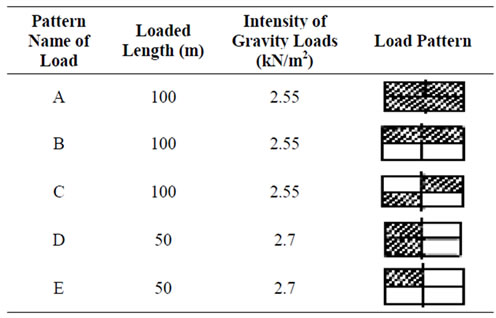
Table 1. Applied patterns of live loads.
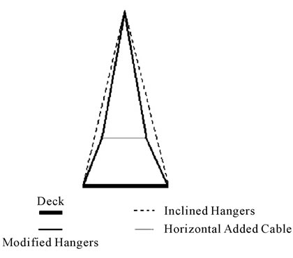
Figure 4. Proposed model of hangers.
hangers gave maximum forces and displacements under A and D load patterns. It was observed that none of the vertical or inclined hangers became slack for the load pattern A. However, the load pattern D caused slackness in some hangers. To remove slackness and overstress in the inclined hangers, excessive forces should be transferred from overstressed hangers to the adjacent slacked hangers. For this reason, a modification was done according to the figure 4. Different H and L (parameters as shown in figure 5) were used by try and error to get optimum results. Different heights were used for H parameter and L was kept constant. It was found that H = 2 m gave good results. Then different L values were given. Initially, big values were given for L parameter then the values were decreased.
It was realized that by decreasing the length of horizontal member (L), the amount of hanger tensile forces decreased until L reached to 0.4 m and then the tensile forces in hangers did not change considerably. It should be noted that the length of horizontal added member should not be less than a specified amount. Because the two inclined cables above the horizontal added member will tend towards the vertical position and hence the inclined hangers will change into the vertical hanger. Figures 6-8 show the plots for H = 1, 2 and 3 m and L = 0.4 m. Figure 9 shows the plots for H = 2 m and different L’s. The cross sectional area of the horizontal members and hangers was used as 283 mm2. The modified model proposed for hangers is shown in Figure 10.
3.1. Comparison of the Analysis Results for Vertical, Inclined, and Modified Hangers
Under the load pattern A in table 1, the analysis showed that slackness did not occur in the hangers (see figure 11). Analysis showed that hanger slacking occurred when
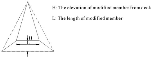
Figure 5. The specifications of modified hangers.
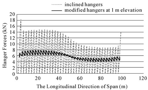
Figure 6. Hanger forces in the bridge with inclined and modified hangers for H = 1 m and L = 0.4 m.
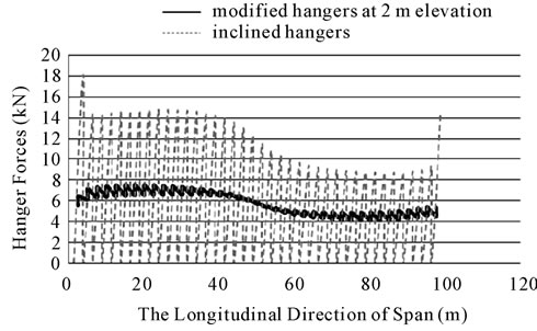
Figure 7. Hanger forces in the bridge with inclined and modified hangers for H = 2 m and L = 0.4 m.
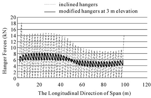
Figure 8. Hanger forces in the bridge with inclined and modified hangers for H = 3 m and L = 0.4 m.

Figure 9. Hanger forces in the bridge with inclined and modified hangers for H=2 m and L = 0.2, 0.5, 0.7 and 1 m.
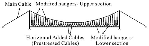
Figure 10. The suspension bridge with modified hangers.
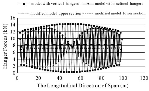
Figure 11. The force of vertical, inclined and modified hangers due to the load A.
the load pattern D in table 1 was applied (see figure 12). From this figure it is seen that 7 vertical hangers and 39 inclined hangers have been slacked. It is also seen that maximum tensile force in vertical hangers is 11.8 kN and is 18.25 kN in inclined hangers. Considering the figure 12, it is realized that, slacking an overstressing in inclined hangers is more than the vertical hangers. The number of vertical and inclined hangers in two models is equal. Figure 13 shows the amount of forces in upper sections of modified hangers (where hangers are connected to main cables) under the dead and live loads. No slacked or tendency to slacked hangers is realized. The maximum tensile force obtained, was 7.8 kN that is within the permitted range. The difference between the
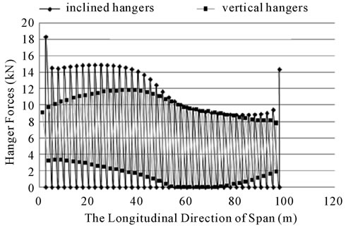
Figure 12. The force of vertical and inclined hangers due to load D.
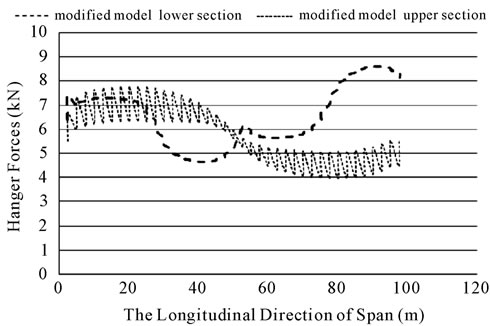
Figure 13. The force of modified hangers due to the load D.
maximum forces in each of two adjacent hangers is about 16 percent.
The fluctuation of forces in vertical and inclined hangers is higher than the fluctuation of forces in the modified system. Therefore, the modified system is less subjected to failure due to fatigue than other systems. The forces of the lower sections (where the hanger is attached to deck) of modified hangers is presented in figure 13. No slacked or tendency to slacked hanger is seen. The maximum tensile force obtained was 8.6 kN. Figure 14 shows the hanger forces for vertical, inclined, and modified systems according to the load pattern D. It is seen that the modification has decreased the value of the tensile force about 123 percent, comparing with the force in inclined hangers. The amount of force in horizontal members changes from 2.5 kN to 2.9 kN across the span.
The results of hanger forces are given in table 2. According to this table, the modified model shows that for all loads in table 1, no slackness or tendency to slackness exists. Also internal forces and their fluctuations decrease significantly in modified hangers in comparison with the vertical and inclined hangers.
3.2. Comparison of Forces of the Main Cables
Main cables axial forces are shown in figure 15 for bridges with vertical, inclined and modified hangers due to the load pattern D. Maximum forces in the main cables are 641 kN, 684 kN and 644 kN for vertical, inclined and modified hangers respectively. According to the figure, the forces of the main cables—for the modified bridge—have decreased in half of the span, and have increased in another half of the span. But the important point is that the maximum force of the main cables has decreased in bridge with the modified hangers comparing with the bridge with inclined hangers. The forces of the main cables for the load pattern A, are presented in figure 16.
3.3. Comparison of Axial Forces in Stiffening Beams
The diagram of axial forces in stiffening beams is presented in figure 17 for bridges with vertical, inclined and modified hangers due to the load pattern D. According to the diagram, the maximum axial forces are 150 kN and 113 kN and 111 kN for vertical, inclined and modi-
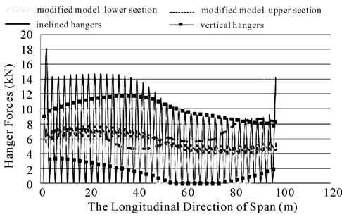
Figure 14. The force of vertical, inclined and modified hangers due to the load D.
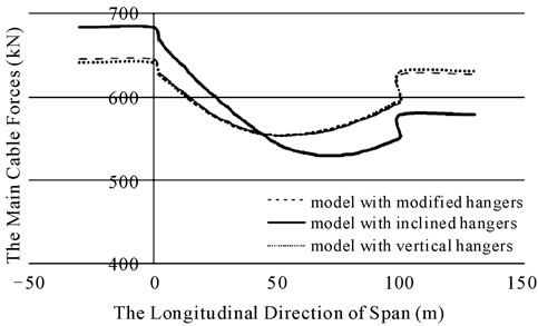
Figure 15. Main cables force in bridges with vertical, inclined and modified hangers due to the load D.
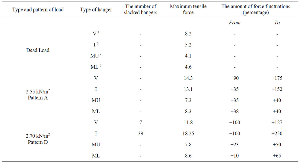
Table 2. Forces of vertical, inclined and modified hangers for live loads.
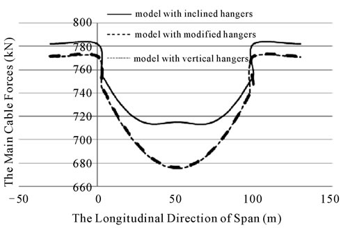
Figure 16. Main cable forces in bridges with vertical, inclined and modified hangers due to load A.
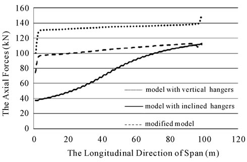
Figure 17. Axial forces in stiffening beams for bridges with vertical, inclined and modified hangers due to load D.
fied hangers respectively. All axial forces are tensile forces and the lowest axial forces belong to the modified bridge. The diagram of axial forces in stiffening beams is presented in figure 18 for the load pattern A.
3.4. Comparison of Bending Moments in Stiffening Beams
The diagram of bending moments in stiffening beams is presented in figure 19 for bridges with vertical, inclined, and modified hangers due to the load pattern D. From this figure, the inclined model bending moments are less than the moments of modified and vertical models.
To decrease the bending moment of the deck, increasing the bending stiffness of the deck can be a solution. In order to increase the deck stiffness, using the stiffening trusses, spanning cables, stay cables, wind guys and creating a high camber to bridge deck is proposed. In this paper, the main purpose is the improvement of slackness and overcoming to overstress problems, and also reducing the fluctuations of hanger forces. Another diagram of bending moments in stiffening beams is given in the figure 20 due to the load pattern A.
3.5. Comparison of Shear Forces in Stiffening Beams
Figures 21 and 22 show the diagram of shear forces in stiffening beams for bridges with vertical, inclined, and modified hangers due to the load patterns D and A re-
Figure 18. Axial forces in stiffening beams for bridges with vertical, inclined and modified hangers due to load A.
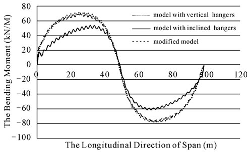
Figure 19. Stiffening beams bending moments in bridges with vertical, inclined and modified hangers due to load D.
spectively. According to the figure 21, the maximum shear force in the deck is about 14 kN related to the vertical system. As it seen from both diagrams, the shear forces in the deck, for three models are almost the same.
3.6. Comparison of Forces and Moments in Towers
Bending moment, axial force and shear force diagrams are presented in figures 23-25 respectively. Only the diagrams of the load pattern D were presented here because they were the most critical cases. In figure 23 the maximum positive moments were 43, 36 and 43 kN/m and maximum negative moments were 300, 243 and 278 kN/m for vertical, inclined and modified hanger systems, respectively.
The axial forces of the towers were always compression forces. The maximum axial forces of the tower were 579, 547 and 459 kN for vertical, inclined and modified hanger systems, respectively. According to the shear force diagram, the maximum shear forces in the tower were 172, 139 and 161 kN for vertical, inclined and modified hanger systems, respectively.
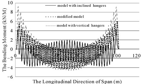
Figure 20. Stiffening beams bending moments in bridges with vertical, inclined and modified hangers due to load A.
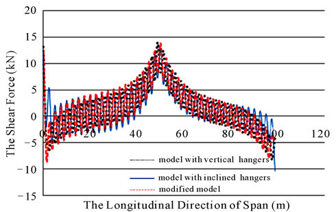
Figure 21. Shear forces in stiffening beams in three hanger systems due to load D.
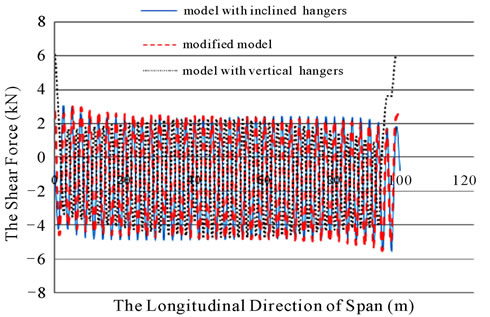
Figure 22. Shear forces in stiffening beams in three hanger systems due to load A.
3.7. Comparison of Vertical Displacements of the Deck
Load pattern D was critical case for displacements of the deck. Here, only the displacements of the bridge deck and is presented in figure 26. For the load pattern D, the maximum vertical displacement of the bridge deck occurred in the quarter length of the deck. According to figure 26, the maximum and minimum displacements
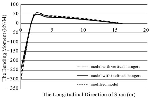
Figure 23. The bending moments in towers in bridges with three different hanger systems due to load D.
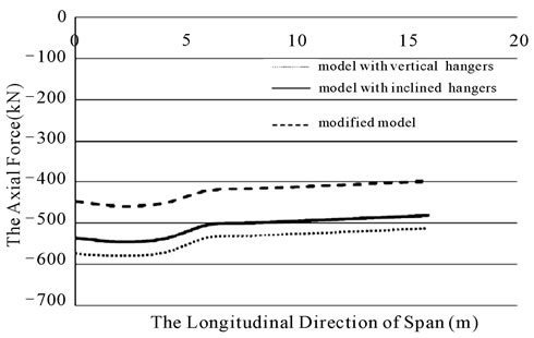
Figure 24. The axial forces in towers in bridges with three different hanger systems due to load D.
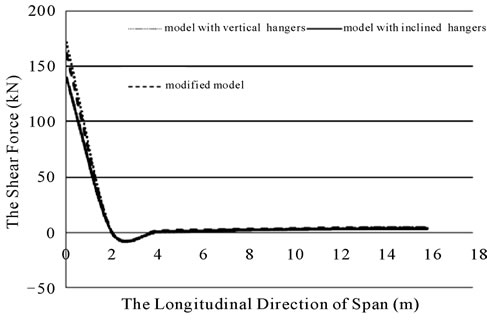
Figure 25. The shear forces in towers in bridges with three different hanger systems due to load D.
belong to the bridge with vertical and inclined hangers respectively. In the bridge with modified hangers, displacements were decreased in comparison to the bridge with vertical hangers.
4. Conclusions
Inclined hangers in suspension bridges improve the aero-
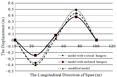
Figure 26. The vertical displacements of the deck in bridges with different hanger systems due to load D.
dynamic stability of the structure and also act like a bracing against bridge longitudinal forces and wind, while the vertical hangers are subjected to greater fluctuations of stress resulting from bridge longitudinal forces and wind loads. Inclined hangers are more liable to fatigue. Some inclined hangers show considerable signs of distress and some of them show slackness due to their location against loads. The total number of slacked hangers depends on the amount and pattern of the applied load. To overcome the disadvantages of inclined hangers, a modification to inclined hangers is proposed. From non-linear static analysis and modeling a pedestrian suspension bridge (as a case study) with three different hanger systems, the following results were obtained:
• The proposed modification in hangers reduces the tensile forces of inclined hangers significantly, and the possibility of slacking - for all hangers - is removed. The reason is that the overstressing forces transfer to the adjacent slacked hanger by the means of a horizontal member added between two adjacent hangers. The modification decreases fluctuations in hanger forces significantly; therefore, it decreases fracture due to fatigue in hangers.
• The maximum axial forces of main cables in the bridge with modified hangers are less than the forces in the bridge with inclined hangers. Also these forces are nearly identical to the forces of main cables in the bridge with vertical hangers.
• The bending moments of stiffening beams are almost identical in modified and vertical hangers, while, for inclined hangers, they are less than the moments of modified and vertical models. To decrease the bending moment of the deck, increasing the bending stiffness of the deck can be a solution. In order to increase the deck stiffness, using the stiffening trusses, spanning cables, stay cables, wind guys and/or creating a high camber to bridge deck is proposed. The amount of axial forces in stiffening beams is less for inclined hangers, while it is high for vertical hangers. The amount of axial forces for modified hangers is between those two. Shear forces in stiffening beams are almost identical for three systems.
• The bending moment and shear force of towers are very close to each other for three systems. The axial force of towers in the modified model shows improvement considerably comparing with the two other hanger systems.
The maximum vertical displacements of the deck for modified hanger system, generally, are almost between the maximum vertical displacements of the deck for two other hanger systems.
5. REFERENCES
- G. Neils, “Cable Suspension Bridge,” John Wiley and Sons, New York, 2000.
- N. Gimsing; “Cable Supported Bridges: Concept and Design,” John Wiley and Sons, New York, 1997.
- Q. Wu, K. Takahashi and S. Nakamura, “The Effect of Loosening of Cables on Seismic Response of the Cable-Stayed Bridge,” Riron Oyo Rikigaku Koenkai Koen Ronbunshu Journal, Vol. 50, 2001, pp. 229-230.
- Q. Wu, K. Takahashi, and S. Nakamura, “The Effect of Cable Loosening on Seismic Response of a Prestressed Concrete Cable-Stayed Bridge,” Journal of sound and vibration, Vol. 268, No. 1, November 2003, pp. 71-84.
- Q. Wu, K. Takahashi, and S. Nakamura, “Influence of Cable Loosening on Nonlinear Parametric Response of Inclined Cables,” NAOSITE: Nagasaki University’s Academic Output Site, Reports of the Faculty of Engineering, Nagasaki University, Vol. 35, No. 65, 2005, pp. 74-81.
- G. C. Sih and X. S. Tang, “Fatigue Crack Growth Rate of Cable-stayed Portion of Runyang Bridge,” Part I—Cable Crack Growth Due to Disproportionate Cable Tightening/Loosening and Traffic Loading, Multiscale Fatigue Crack Initiation and Propagation of Engineering Materials, Springer Science+Business Media, Berlin, 2008, pp. 209-247.
- A. C. Lazer, and P. J. Mckenna; “Large-Amplitude Periodic Oscillations in Suspension Bridges: Some New Connections with Nonlinear Analysis,” Siam Review, Vol. 32, No. 4, December 1990, pp. 537-578. doi:10.1137/1032120
- I. Peterson, “Rock and Roll Bridge: A New Analysis Challenges the Common Explanation of a Famous Collapse,” Science News, Vol. 137, No. 22, 1990, pp. 344- 346. doi:10.2307/3974221
- V. Sepe and G. Augusti, “A Deformable Section Model for the Dynamics of Suspension Bridges, Part I: Model and Linear Response,” Wind and Structures, Vol. 4, No. 1, 2001, pp. 1-18.
- J. Suh and S. P. Change, “Experimental Study on Fatigue Behaviour of Wire Ropes,” International Journal of Fatigue, Vol. 22, No. 4, April 2000, pp. 339-347. doi:10.1016/S0142-1123(00)00003-7
- B. H. Ali, “An Investigation into the Static Behavior of the Severn Bridge,” M.Sc. Thesis, UMIST, Manchester, 1984.
- E. V. Chipuru, “Guidelines for the Design and Construction of Suspension Footbridges,” ILO/ASIST, Harare, Zimbabwe, 2001.
- M. A. Al-Khlili, “An Investigation into the Static Behaviour of the Existing Inclined Hanger System on the Severn Suspension Bridge,” M.Sc Thesis, UMIST, Manchester, 1986.