Communications and Network
Vol. 4 No. 4 (2012) , Article ID: 25002 , 4 pages DOI:10.4236/cn.2012.44033
Realization of Network Bypass Protecting Instrument Based on ARM-Linux
Department of Physics and Electronic Engineering, Hubei University, Wuhan, China
Email: ganyiming@hubu.edu.cn, *tianmao@hubu.edu.cn
Received July 1, 2012; revised August 22, 2012; accepted September 5, 2012
Keywords: ARM-Linux; U-Boot; Network Bypass Protecting Instrument; AT91RM9200
ABSTRACT
With the control mode of value-added network services equipment changing from bypass intervention to serial control, in order to minimize the security problems which are caused by the failure of the network equipment, this paper proposes a stable, fast and intelligent network bypass protection system combined with the ARM embedded system—Linux platform. In practical application, the system can automatically skip the broken-down device node to protect the network to be unobstructed. With the features of fast response, stable operation, low power consumption, and the flexible of combination, the scheme is proved to have large practical value.
1. Introduction
With the prosperity and development of Internet applications, network equipments of value-added services also develop rapidly. At present, most value-added services devices are changed from the bypass intervention to serial control intervention. To minimize the network security risks caused by the introduction of equipment failure, the system needs a stable and fast intellectual protection system which can automatically skip the failing node and protect the network unobstructed in the value-added services.
2. System Design
WThe main purpose of the system is to use the rich internal resources of the AT91RM9200 to design a costeffective network equipment bypass protection. Combined with the bypass protection devices, the network value-added services can make the entire network be strong and effective self-healing power, to ensure network safety and reliability.
By adopting the AT91RM9200 processor, the bypass protection hardware communicates with the monitored device through Ethernet interface. When the bypass device does not receive the heartbeat response packet which transmitted by the monitored equipment in a set time, the bypass device will change the other links automatically and keep away from the failed node. While when the bypass device receives the normal heartbeat packet, bypass device will automatically access to the network. In order to adapt to specific environments, the bypass device also can accept programmed commands or keyboard parameters setting [1] . The system hardware block diagram is shown in Figure 1.
3. Hardware Design
3.1. The Circuit of the Master Control Board
Taking into account that the bypass device only receives heartbeat packets and some programmed commands and the data transmission is low, while the device must be well in real-time, the design chooses the ATMEL AT91RM9200 which is ultra-low power consumption as the main controller. The ARM9 is rich in peripherals, there is an integrated 10/100 Base-T Ethernet card interface, 2 UARTs, the rich GPIO resources will fully meet the needs of system hardware, greatly simplify the hardware design. Link switching control signal comprises the PA18 - PA25 8 GPIO lines which can control the access state independently, so the networking style is more diversified. Because the system does not need much storage capacity, we choose the MX29LV640 (8 MB) as the Flash, and choose the HY57V281620HCT as the SDRAM.
3.2. The Circuit of the Sub-Board
According to the different network communication medium, there are power port and optical port in the sub circuit board. There are a number of low-power high sensitivity relays which complete the state switch of the

Figure 1. The system hardware diagram.
links according to the control signals from the master control board in the power port control sub board. The optical port sub board chooses the micro mechanical optical switches which is low in insertion loss to complete the switch of the links from the physical switch.
The SUN-FSW-D2 × 2 BT produced by the Guilin Guang Long was chosen as the optical switch which supports two optical ports switches simultaneously. Because the work level of the optical switch is 5 V, the 74HCT245 was adopted to convert the control signal 3.3 V to 5 V. The drive capability of the optical switch must be greater than 25 mA, taking into account that the MCU I/O ports drive capability is not enough, we added the current driving amplifier. The optical signals were converted to electrical signals, and then collected by the A/D after appropriate amplifying. The A/D converter is selected as TLV2556 which is 12-bit, 11 road and low-power serial A/D chip.
4. Software Design
The software design and development process based on the OS including the design and porting of the bootloader, cutting and transplantation of the operating system, the development of the hardware drivers and application. The bootloader initialize the hardware and boots the operating system. The system uses u-boot-1.2.0, and produces the JFFS2 file system. The executable and configuration files, and the log directories are on the/ home directory.
4.1. U-Boot Design and Transplantation
U-boot transplantation [2] : According to the configuration of the master control board, the u-boot is needed to be modified. The mainly modification is to change the flash driver to match the flash configuration of the master control board.
In order to facilitate the upgrading of the system software, the u-boot was designed to upgrade automatically when it finds the upgrading server, and complete the software system upgrading through the TFTP protocol. When the upgrading server is not found the u-boot boots linux kernel to complete system start. The system upgrading is full transparency and automatic for the users.
As a 10/100 Base-T Ethernet card interfaces was integrated in the AT91RM9200, the physical card employed soft card RTL8201BL. Soft card is without curing the unique MAC address, setting the MAC address is a problem in the u-boot. If the two systems which MAC address is the same on the same LAN, they will influence each other. In order to generate the unique MAC address, and pass to the kernel of the NIC driver, the system uses the time of system upgrading as a random seed to generate a random number, the unique MAC address was obtained after processing the random number. Then the address was saved in the u-boot environment variable ethaddr, and then through the command-line argument list, the MAC address was passed to the linux kernel by boot-m.
4.2. The Kernel Relevant Hardware Drivers
The modifications of the kernel network driver: Linux- 2.6.20 kernel version was adopted, driver/net/arm/at91_ ether.c and ether.h under the linux kernel have adaptive to the card RTL8201BL, we must modify the drive to get the unique MAC address passed by u-boot because that RTL8201BL is soft card [3] . We get the MAC address by analyzing the u-boot parameters, then modify the static void__init get_mac_address (struct net_device*dev) function at 91_ether.c, we will obtain the member variable dev_addr of the net_device structure. The MAC address was saved in the dev_addr.
The implement of the GPIO driver [4] : GPIO driver is a simple character device driver. We complete the device open (), ioctl () in the driver. When the device is on normal open state, the application can easily set the GPIO state by calling the ioctl (). The modular loading can be completed by using the init () and exit (). According to the actual needs of the system, it can be set the GPIO initialization state.
4.3. Application Implementation
Application design is designed to be modularization for general using and good implement. There are mainly include the link state control module, programmable command module, UDP heartbeat monitor module, keypad and display module and optical power detection module [5] .
The entire software system is multi-threaded programming and object-oriented processing. The application software flow chart is shown in Figure 2.
• Heartbeat monitoring module: In automatic mode, the bypass device sends the UDP heartbeat packets “T@” to the monitored equipment in accordance with the default heartbeat cycle. The monitored equipment sends the UDP heartbeat packets “A@” back when it works well. If the bypass device does not receive the heartbeat packets sent by the monitored equipment within the preset number of the heartbeat timeout, the monitored equipment will be considered to be abnormal, and to be automatically bypassed to ensure network smooth. Heartbeat cycle and heartbeat timeout times can be set by pressing a button or remote command. The heartbeat cycle can be set from 10 ms to 1000 ms and the step is 5 ms. The heartbeat timeout times can be set from 1 to 255 the step is 1.
• Optical power detection module: The light of each TX optical path of monitored equipment sends to PD which converts the optical signal to electrical signal
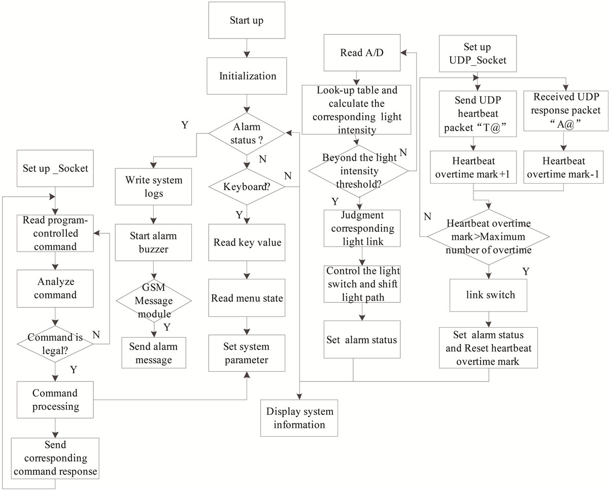
Figure 2. The application software flow chart.
after 3% splitting. The converted weak signal is amplified and sent to the A/D convertor. The optical power detection module is responsible for converting the values collected by A/D to the corresponding optical power dBm in automatic mode. Whenever the monitored equipment does not response or the NIC is not wrong, the monitored equipment will be automatically switched into the corresponding bypassed state. The system automatically switches to the device accessed status when the system detects that the light network card work well and the heartbeat response normally. In manual mode, when the system detects that the monitored device or the optical card is not normal, the monitored equipment will be automatically switched into bypassed state. However, it is necessary to manually switch when restore the device accessed state.
• Remote command module: remote command module is responsible for receiving the remote TCP command packet, analyzing the command, and setting bypass protection system according to the lawful order, such as configuration information corresponding to the monitored device, modifying the configuration information the bypass protection system and monitored device based on the actual physical network model, setting the IP and subnet mask of the system, configuring the network information of the IP and the subnet mask of the bypass protection system based on the actual network environment, real-time monitoring system working state, and return back the system mode other system operation information according to a certain format.
5. Main Performance Parameters Test
Fiber insertion loss depends on the light switch, switching time is the response speed of the monitored equipment in the network state. Range of light intensity detection indicates the ability that the system detects light. After testing the main performance parameters of the bypass protector are shown in Table 1.
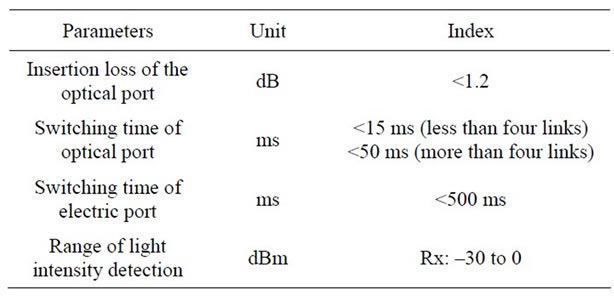
Table 1. Main parameters of the performance.
Test data show that the bypass protection response quickly, works stably and is low power consumption, with good practical and marketing value.
6. Conclusion
The application shows that the system provides a practical, reliable and intelligent solution to protect communication network security. The system can automatically skip the failing node and ensure the network to be unobstructed. And the system can control the multi links independently, which is convenient for the network devices and bypass protection system one-to-many and many-toone networking flexibly.
REFERENCES
- W. R. Stevens, B. Fenner and M. R. Andrew, “UNIX Network Programming: The Sockets Networking API,” Prentice Hall, London, 2004.
- W. Mauerer, “Professional Linux Kernel Architecture,” Wiley Publishing, Inc., Indianapolis, 2008.
- T. Z. Sun, Y. W. Ju and H. F. Zhang, “Embedded Linux Driver Development Guide the Design and Guidelines,” Electronic Industry Press, Beijing, 2005.
- J. Corbet and A. Bubini, “Linux Device Drivers,” 3rd Edition, Oreilly & Associates Inc., Sebastopol, 2005.
- Z. R. Liu, C. C. Chang and S. Xu, “Embedded Linux Application and Development Solutions,” Mechanical Industry Press, Beijing, 2004.
NOTES
*Corresponding author.