Intelligent Control and Automation
Vol.09 No.02(2018), Article ID:84911,12 pages
10.4236/ica.2018.92004
Negative Imaginary Approached High Performance Robust Resonant Controller Design for Single-Phase Islanded Microgrid and Its Voltage Observation on Different Load Condition
Arnob Kumar Bairagi1, Ahasan Habib1, Rakib Rahman1, Motiur Rahman2, Moniruzzaman Jewel3
1Department of Electrical and Electronic Engineering, Rajshahi University of Engineering & Technology, Rajshahi, Bangladesh
2Department of Electrical and Electronic Engineering, Bangladesh Army University of Engineering & Technology, Natore, Bangladesh
3Institute of Information and Technology, Jahangirnagar University, Savar, Bangladesh

Copyright © 2018 by authors and Scientific Research Publishing Inc.
This work is licensed under the Creative Commons Attribution International License (CC BY 4.0).
http://creativecommons.org/licenses/by/4.0/


Received: April 21, 2018; Accepted: May 27, 2018; Published: May 30, 2018
ABSTRACT
This paper presents the design of a high performance robust resonant controller for the islanded single-phase microgrid operation on different loads conditions. The design of the controller is done using the results of Negative Imaginary approach. The performance of the proposed controller has been found much effective to track the instantaneous reference grid voltage. The simulation work has been done with the help of MATLAB/SimPower System toolbox. This shows that the proposed controller provides effective control of voltage against the uncertain load conditions.
Keywords:
Controller Design, Islanded Microgrid, Robust Voltage Control

1. Introduction
The necessity of continuous power supply to the load is increasing day by day. Due to this necessity the concept of Microgrid (MG) has come out. It is a part of distribution generation (DG) system [1] . The MG system is associated with low or medium distributed energy (DE) sources like wind turbines, PV (Photovoltaic cells), micro-turbines, fuel cells etc. This system is also related with consumer loads and energy storage systems (ESS) [2] [3] .
The Microgrid can be operated in two modes. They are the grid connected and the islanded (stand-alone) mode [3] [4] . In grid connected mode, the DG unit voltage and frequency are controlled by the central Main-grid. In this system, the main grid is connected with the microgrid with the help of PCC (Point of Common Coupling). Here all the power supply areas are served by the main grid’s determined voltage and frequency [4] [5] . In this mode, the DG units supply there real and reactive power by using current control strategy [6] .
And the second one is Islanded (stand-alone) mode. This mode is activated when large type of disturbance like faults, voltage collapse or poor power quality in the main grid [6] . This mode is preferable for those areas where the main grid operation is not beneficial due to long transmission loss or where the continuous power supply is the most priority issue [7] [8] . During the pick power condition, the MG system provides uninterrupted power to that load.
In a microgrid system, different types of faults can be occurred during its operation period. But when these faults are removed, there appear sudden changes in voltage level. This sudden change in voltage can cause large variation of voltage level during its transient period [8] [9] . For this, proper automated control system is essential.
Various strategies have been proposed in the recent years for the control of dc microgrid. Among then the droop control, hierarchical control, proportional-resonant (PR) control, PID control etc. are most effective.
The most well-known control technique for microgrid is the droop control technique. This is used for voltage and frequency control [10] . It ensures proper power sharing among the DG units. As it generally uses parallel inverters so that this can provide balancing power for both the grid connected and islanded operation of microgrid [11] [12] . But the main problem with this technique is that when it operates any dynamic loads then the voltage and frequency become unstable and this limits the power sharing accuracy of the MG.
The Proportional-Integral-Derivative (PID) controller is used for both the voltage and frequency regulation of microgrid system. Besides, it is used for maintaining the power balance. This control strategy can reduce the steady-state error and can improve both transient and steady-state responses [13] [14] . The main advantage of this technique is its simplicity and ease to use. The grid operator does not need high level of knowledge to design it. But the major drawbacks of this controller are that, it can’t show much robustness during the operation of load dynamics. Besides it does not have enough bandwidth for the peak time operation of microgrid [14] .
The deadbeat controller is used for the control of voltage and current in the MG. As it is generally a mathematic based controller so it provides fast transient response with less overshoot. Besides it reduces the switching frequency of the inverter [15] . But the drawback of this controller is that it is so much sensitive to the load parameters. This means if the load parameters can’t remain constant then the performance of the controller will decrease though it has good dynamic response [15] .
Distributed frequency and voltage control for MG system have been proposed for better voltage and frequency deviation [16] [17] . According to this technique the controller measures number of parameters from the remote sensing block and send it back to the controller. But the main problem is that it reduces the efficiency of the system for its slow control loop system and low bandwidth [18] .
Another multi-level control technique called Hierarchical is being used to achieve higher BW and steady-state performance for voltage and frequency control of the grid system. This strategy has three levels known as primary, secondary and tertiary level [19] [20] . Each level has different types of controllers and they perform specific control objectives. If one level is temporary shut down due to the faults, then the other control levels can’t successfully regulate the power sharing in the microgrid.
In this paper, we have proposed a controller named resonant controller for the voltage control of single-phase microgrid system. The terms that have motivated us to design this is its simplicity, having low order transfer function matrices and this controller does not require advanced knowledge of mathematics. The stability analysis of the resonant controller for MG has been done from the results of Negative Imaginary (NI) theory [21] . The performance of the controller is simulated using MATLAB 2017 environment. Besides the controller performance has been observed under different load conditions, which shows that the controller provides extensive performance for the microgrid system.
The rest of the paper is organized as follows. Section 2 presents the modeling of Islanded MG. section 3 presents the design of the resonant controller. The stability of the controller has checked in section 4. And the performance of the proposed controller has been discussed in section 5.
2. Modeling of Single-Phase Islanded Microgrid
2.1. Microgrid Outline
The closed-loop microgrid consists of input energy source (ES), a single stage voltage source inverter (VSI), output LC filter, line and load impedance and point of common coupling (PCC). Here, the single-phase inverter is used to convert the DC energy voltage into AC and makes it useable for the practical grid line use [22] . IGBT based VSI has been used and switching action of it is
represented by where, and is the DC
voltage. In Figure 1, the filtering LC circuit is used to reduce the switching ripple of the inverter. A single point of common coupling (PCC) is used for the addition of microgrid network with the main grid network.
In the MG system the control of the VSI has done with the help of the reference grid voltage. In the Figure 1, the blue box is considered as the proposed
controller which creates link among the measured grid voltage and reference grid voltage and moderate the duty cycle of the VSI.
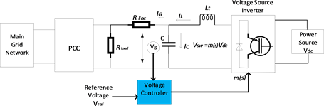
Figure 1. Single-phase microgrid system.
2.2. Single-Phase MG Mathematical Model
From Figure 1, the inductor current is given by the following equation,
(1)
here, and are defined as the grid current and capacitor current respectively. Now let us consider as the Inductor voltage. Then the current into the inductor is
(2)
or (3)
But the Laplace transform of (2) is
(4)
or
or (5)
But the product of duty ratio of inverter is the switching voltage or . And there remains also the renewable dc voltage source . So, we can rewrite,
(6)
In Figure 1, as the capacitor is placed parallel to the main grid, for capacitor voltage we can write,
(7)
or
or (8)
here, defines the capacitor current. The LT of Equation (8) will be
(9)
From (5) and (9) we can write
(10)
And the output of the overall system is
(11)
If we drive Equations (10) and (11) as state-space re-presentation then we get,
(12)
(13)
That means, state matrix , input matrix, , output matrix, . Here, transition matrix, .
The different parameters have given in the Table 1.
3. Controller Design
In this paper our aim is to design a controller to recompose the unwanted oscillation of MG when it is on its Islanded mode. For this purpose, we have proposed a robust positive-position feedback controller. It is designed to recompose the unwanted voltage oscillation in microgrid It is a closed-loop system shown in the following Figure 2.
From the Figure 2, it can be observed that the single phase microgrid can be compared with the SISO (Single Input Single Output) system. So, we have to design such type of controller that can control a SISO system. To design it we have applied NI theory [21] .
From the SNI theorem we can write
(14)

Table 1. Grid parameters for single phase microgrid system.
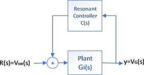
Figure 2. Block diagram of closed-loop system.
where and are the controller gain, damping constant and the
frequencies respectively. But when Equation (14) is implemented as positive-real feedback controller then controller can be written as
(15)
here the numerator is the first order polynomial and it depends on the closed-loop nature of the system. For SISO system can be considered as . Then Equation (15) can be written as
(16)
Now from Equation (14) & Equation (16) it can be written that
(17)
The transfer function of resonant controller is as follows,
(18)
The controller parameters are given below.
In Table 2, We have chosen low gain for the proposed controller with low frequencies. And this decision has increased the controller gain and phase margin. Here, the low value of the damping constant would introduce the unexpected phase shift while the high value of it could provide low damping in the closed-loop system.
4. Stability Checking
From the Negative Imaginary theory [21] a transfer function is said to be NI if and only if there have no poles at the origin or in the open right half plane (ORHP) and in the interval of −180 to 00 at any frequencies. From the transfer function , it is defined that it has no poles at the origin. Besides, the transfer function of closed-loop system from Figure 2, it can be written that,
(19)
Table 2. Controller parameters for Single-Phase Microgrid.
In Equation (19) the phase shift of the system lies between −180 to 00 defined from bode plot in Figure 3. So, this system follows the NI theory. For stability the parameters of the controller have chosen in such a way that the product of loop gain is always less than one.
5. Performance Evaluation
In this section, the performance of the proposed controller has observed against different load condition such as non-linear loads, unknown loads, harmonic loads, consumer loads, asynchronous load conditions and they have drawn in the above Figure 4. All this simulation is done in MATLAB environment. From the simulation results of Figures 5-9 it can say that, the proposed closed-loop resonant controller has showed maximum robustness against the open-loop uncontrolled voltage.
5.1. Consumer Load
In our case study, for simulation purpose we have considered resistance ( ) as consumer load. Figure 5 shows the performance of the controller. When the MG suddenly turns into its islanded mode, the closed-loop resonant controller takes its voltage level into a stable level.
5.2. Non-Linear Load
In this case study, here the performance of resonant controller has observed against the non-linear load like air-conditioners, televisions etc. But for our MATLAB simulation purpose here we have used diode bridge rectifier (two-phase four pulse) with RC load ( , ) which is connected with the main grid (shown in Figure 4(a)). From the performance Figure 6, it can decide that the proposed controller have showed the maximum robustness against the non-linear loads.
5.3 Unknown-Load
In Figure 7, the performance of the controller has been observed against the unknown load when it is connected with the main grid. At first, the MG was operated in a steady state voltage, and at time t = 0.2s the passive load resistance, capacitance, inductance have changed. But the peak amplitude of the voltage remains unchanged for the presence of the proposed controller. This comparison also proves the robustness of the proposed controller.

Figure 3. Bode plot of loop gain represented by green dashed line (--); controller represented by red dashed line (--) and nominal plant gain represented by blue solid line (-).

Figure 4. Connecting with (a) Non-linear load; (b) Unknown load; (c) Harmonic load; (d) Asynchronous load.
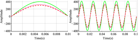
Figure 5. Voltage tracking of consumer load. Here green solid line (- ), pink solid line (-) and red dashed line(--) represents the reference MG voltage, open-loop MG voltage and closed-loop resonant controller MG voltage.
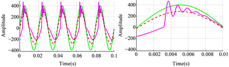
Figure 6. Voltage tracking of non-linear load. Here green solid line (- ), pink solid line (-) and red dashed line(--) represents the reference MG voltage, open-loop MG voltage and closed-loop resonant controller MG voltage.
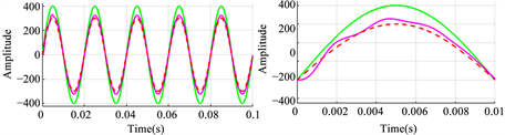
Figure 7. Voltage tracking of unknown load. Here green solid line (- ), pink solid line (-) and red dashed line(--) represents the reference MG voltage, open-loop MG voltage and closed-loop resonant controller MG voltage.
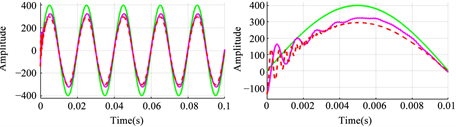
Figure 8. Voltage tracking of Harmonic load. Here green solid line (- ), pink solid line (-) and red dashed line(--) represents the reference MG voltage, open-loop MG voltage and closed-loop resonant controller MG voltage.
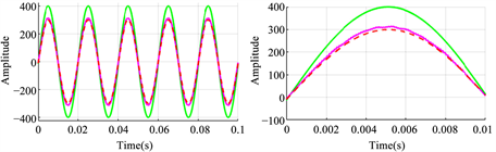
Figure 9. Voltage tracking of Asynchronous load. Here green solid line (- ), pink solid line (-) and red dashed line(--) represents the reference MG voltage, open-loop MG voltage and closed-loop resonant controller MG voltage.
5.4. Harmonic Load
When non-linear loads are connected parallel to the MG, then there happens voltage and current distortion. Non-linear loads like computers, printers, television, rectifiers etc. cause harmonics. This harmonic voltage increases the heat of the loads and reduce the lifetime of the loads/devices. Besides, the non-linear loads produce extra current when it is connected with the electric system. Different types of harmonics are produced by the non-linear loads. The main dis-advantage of this harmonic is that it increases the current of the system. So, there needs a voltage controller to control this unwanted voltage results out from harmonic loads. In Figure 4(c), there represents a model of 3rd harmonics load with 30 Ω resistance and 7 A (150 hz) current source connected in series. The performance of the proposed controller is presented in Figure 8. From the results, it is seen that the proposed controller has excellent damping oscillation efficiency.
5.5. Asynchronous Load
For this asynchronous load simulation, here we have connected an induction load with the MG network which have shown in Figure 4(d). This induction motor is modeled as a dq stator reference frame with capacitor-start and capacitor-start-run respectively. This dynamic load will affect the voltage because of the variation of active and reactive power of it. The performance of the proposed controller has showed in Figure 9. For the use of proposed controller, we will see the robustness of it.
6. Conclusion
In this paper, we have proposed SISO system based resonant controller for microgrid. The design of the controller has done with the results come out from robust NI theory. This controller has maintained the closed-loop stability of the MG against the open-loop stability. The experimental implementation has done in the MATLAB environment which shows us the robustness of the proposed controller successfully.
Cite this paper
Bairagi, A.K., Habib, A., Rahman, R., Rahman, M. and Jewel, M. (2018) Negative Imaginary Approached High Performance Robust Resonant Controller Design for Single-Phase Islanded Microgrid and Its Voltage Observation on Different Load Condition. Intelligent Control and Automation, 9, 52-63. https://doi.org/10.4236/ica.2018.92004
References
- 1. Borazjani, P., Wahab, N.I.A., Hizam, H.B. and Soh, A.B.C. (2014) A Review on Microgrid Control Techniques. 2014 IEEE Innovative Smart Grid Technologies-Asia (ISGT ASIA), Kuala Lumpur, 749-753. https://doi.org/10.1109/ISGT-Asia.2014.6873886
- 2. Yazdanian, M. and Mehrizi-Sani, A. (2014) Distributed Control Techniques in Microgrids. IEEE Transactions on Smart Grid, 5, 2901-2909. https://doi.org/10.1109/TSG.2014.2337838
- 3. Le Minh, P., Vo Duc, D.H., Xuan, H.P.T. and Minh, H.N. (2017) A New Control Strategy of Power Sharing in Islanded Microgrids. 2017 International Conference on System Science and Engineering (ICSSE), Ho Chi Minh City, 175-179. https://doi.org/10.1109/ICSSE.2017.8030860
- 4. Ramezani, M. and Li, S. (2016) Voltage and Frequency Control of Islanded Microgrid Based on Combined Direct Current Vector Control and Droop Control. 2016 IEEE Power and Energy Society General Meeting (PESGM), Boston, 1-5. https://doi.org/10.1109/PESGM.2016.7741786
- 5. Hatziargyriou, N., Asano, H., Iravani, R. and Marnay, C. (2007) Microgrids. IEEE Power and Energy Magazine, 5, 78-94. https://doi.org/10.1109/MPAE.2007.376583
- 6. Azim, M.I., Hossain, M.A., Hossain, M.J. and Pota, H.R. (2015) Effective Power Sharing Approach for Islanded Microgrids. 2015 IEEE Innovative Smart Grid Technologies-Asia (ISGT ASIA), Bangkok, 1-4.
- 7. Vandoorn, T.L., Renders, B., Degroote, L., Meersman, B. and Vandevelde, L. (2011) Active Load Control in Islanded Microgrids Based on the Grid Voltage. IEEE Transactions on Smart Grid, 2, 139-151. https://doi.org/10.1109/TSG.2010.2090911
- 8. Sortomme, E., Mapes, G.J., Foster, B.A. and Venkata, S.S. (2008) Fault Analysis and Protection of a Microgrid. 2008 40th North American Power Symposium, Calgary, 1-6.
- 9. Hooshyar, A., El-Saadany, E.F. and Sanaye-Pasand, M. (2016) Fault Type Classification in Microgrids including Photovoltaic DGs. IEEE Transactions on Smart Grid, 7, 2218-2229. https://doi.org/10.1109/TSG.2015.2451675
- 10. Raj, D.C. and Gaonkar, D.N. (2016) Frequency and Voltage Droop Control of Parallel Inverters in Microgrid. 2016 2nd International Conference on Control, Instrumentation, Energy & Communication (CIEC), Kolkata, 407-411. https://doi.org/10.1109/CIEC.2016.7513771
- 11. Araújo, L.S., Narváez, D.I., Siqueira, T.G. and Villalva, M.G. (2016) Modified Droop Control for Low Voltage Single Phase Isolated Microgrids. IEEE International Conference on Automatica (ICA-ACCA), Curico, 1-6. https://doi.org/10.1109/ICA-ACCA.2016.7778455
- 12. El Moubarek Bouzid, A., Sicard, P., Yamane, A. and Paquin, J.N. (2016) Simulation of Droop Control Strategy for Parallel Inverters in Autonomous AC Microgrids. 8th International Conference on Modelling, Identification and Control (ICMIC), Algiers, 701-706. https://doi.org/10.1109/ICMIC.2016.7804202
- 13. Kumar, B. and Bhongade, S. (2016) Load Disturbance Rejection Based PID Controller for Frequency Regulation of a Microgrid. Biennial International Conference on Power and Energy Systems: Towards Sustainable Energy (PESTSE), Bangalore, 1-6. https://doi.org/10.1109/PESTSE.2016.7516459
- 14. Parise, G., Martirano, L., Kermani, M. and Kermani, M. (2017) Designing a Power Control Strategy in a Microgrid Using PID/Fuzzy Controller Based on Battery Energy Storage. IEEE International Conference on Environment and Electrical Engineering and 2017 IEEE Industrial and Commercial Power Systems Europe (EEEIC/I&CPS Europe), Milan, 1-5. https://doi.org/10.1109/EEEIC.2017.7977856
- 15. Harmouch, F.Z., Krami, N., Benhaddou, D., Hmina, N., Zayer, E. and Margoum, E.H. (2016) Survey of Multiagents Systems Application in Microgrids. International Conference on Electrical and Information Technologies (ICEIT), Tangiers, 270-275. https://doi.org/10.1109/EITech.2016.7519604
- 16. Liu, W., Gu, W., Sheng, W., Meng, X., Wu, Z. and Chen, W. (2014) Decentralized Multi-Agent System-Based Cooperative Frequency Control for Autonomous Microgrids with Communication Constraints. IEEE Transactions on Sustainable Energy, 5, 446-456.
- 17. Wu, X., Shen, C. and Iravani, R. (2016) A Distributed, Cooperative Frequency and Voltage Control for Microgrids. IEEE Transactions on Smart Grid, 1.
- 18. Manshadi, S.D. and Khodayar, M.E. (2018) Expansion of Autonomous Microgrids in Active Distribution Networks. IEEE Transactions on Smart Grid, 9, 1878-1888.
- 19. Bidram, A. and Davoudi, A. (2012) Hierarchical Structure of Microgrids Control System. IEEE Transactions on Smart Grid, 3, 1963-1976. https://doi.org/10.1109/TSG.2012.2197425
- 20. Parhizi, S., Lotfi, H., Khodaei, A. and Bahramirad, S. (2015) State of the Art in Research on Microgrids: A Review. IEEE Access, 3, 890-925. https://doi.org/10.1109/ACCESS.2015.2443119
- 21. Petersen, I.R. and Lanzon, A. (2010) Feedback Control of Negative-Imaginary Systems. IEEE Control Systems, 30, 54-72. https://doi.org/10.1109/MCS.2010.937676
- 22. Micallef, A., Apap, M., Spiteri-Staines, C. and Guerrero, J.M. (2015) Single-Phase Microgrid with Seamless Transition Capabilities between Modes of Operation. IEEE Transactions on Smart Grid, 6, 2736-2745. https://doi.org/10.1109/TSG.2015.2444912