Intelligent Control and Automation
Vol. 3 No. 3 (2012) , Article ID: 22046 , 7 pages DOI:10.4236/ica.2012.33025
Design and Implementation of Electronic Control Trainer with PIC Microcontroller*
Electrical Engineering Department, Engineering College, University of Anbar, Baghdad, Iraq
Email: yousif_phd@hotmail.com
Received April 26, 2012; revised May 23, 2012; accepted May 30, 2012
Keywords: PIC Microcontroller; Photoelectric Sensor; Conventional Electronic Trainer
ABSTRACT
This paper describes the implementation of a PIC microcontroller in a conventional laboratory-type electronic trainer. The work comprises software for the PIC and hardware for the software. The PIC controller uses an EasyPIC-6 board and includes a PC-interfaced programmer for the PIC chip. It has many external modules: 128 × 64 graphic LCD display, 2 × 16 LCD display, 4 × 4 keypad, and port expander, all in the same bench. The trainer is capable of 36 experiments in logic/analogue electronic and control systems. A 5-sided approximate sensor, two photoelectric sensors (BR56-DDT-P and BEN9M-TFR), four CMOS, four BCD-7-segment driven by CD4511B, two relays (2-pole and 3-pole), six voltages, ammeter measurement, DC motor, and 24VDC power supply, connect through connectors and pinions. Results of all the experiments show the trainer satisfying requirements of undergraduate and postgraduate projects involving conventional electronic and classical control systems.
1. Introduction
Modern microcontroller chips can store hundreds of thousands of transistors each. The first microprocessors had external peripherals such as memory, input-output lines, and timers (Matic, 2003). In time came a new device called integrated circuit (IC), which contains both processor and peripherals. Also called a microcontroller, this was the first chip with a microcomputer [1,2].
Peripheral Interface Controller (PIC) is new to electronics control. Providing complete control in a single chip, a PIC microcontroller has special function registers, power on reset, interrupts, user RAM for storing of program data, EPROM program memory, timer circuits, instruction set, low power consumption, and on-board Ato-D converters. It replaces conventional control of industrial machinery (e.g., motor-speed control) [2,3].
Microcontroller and microprocessor differ in many ways. In functionality, a microprocessor needs external components for receiving/sending data, and memory. A microcontroller does not need external components because all the necessary peripherals are built-in, saving time and space (see Figure 1 for microcontroller set [4- 7]).
The EasyPIC-6 by MikroElektronika (see Figure 2) is an extraordinary development tool for programming and experimenting with PIC® microcontrollers. It supports over 160 MCUs in PIC10, PIC12, PIC16, and PIC18 families, in DIP packages from 8 to 40 pins. The board comes installed with PIC16F887. An impressive array of peripherals and expansion connectors are available onboard, as are optional LCD displays and temperature sensor [8,9].
An on-board programmer and mikroICD debugger allow direct connection to PC via USB cable. Fully functional demo versions of MikroElektronika’s C, Pascal, and BASIC compilers are included (hex output limited to 2K program words), complete with documentation and dozens of sample programs. The EasyPIC-6 also includes an external ICD connector compatible with MPLAB ICD2 and ICD3, allowing full compatibility with MPLAB Integrated Development Environment (IDE) [10,11].
Its main problem is lack of facility for external experiments to be implemented in many undergraduate laboratory applications; it is also daunting to beginner designers. This paper presents a practical implementation of EasyPIC-6-based electronic control trainer able to execute about 36 experiments, and rearrangement of the EasyPIC-6 power supply to extend the trainer’s capability to AC-DC-current applications.
1.1. Integrated Development Environment (IDE)
The core development tool set operates under the IDE umbrella called MPLAB. The tools look and feel the same,
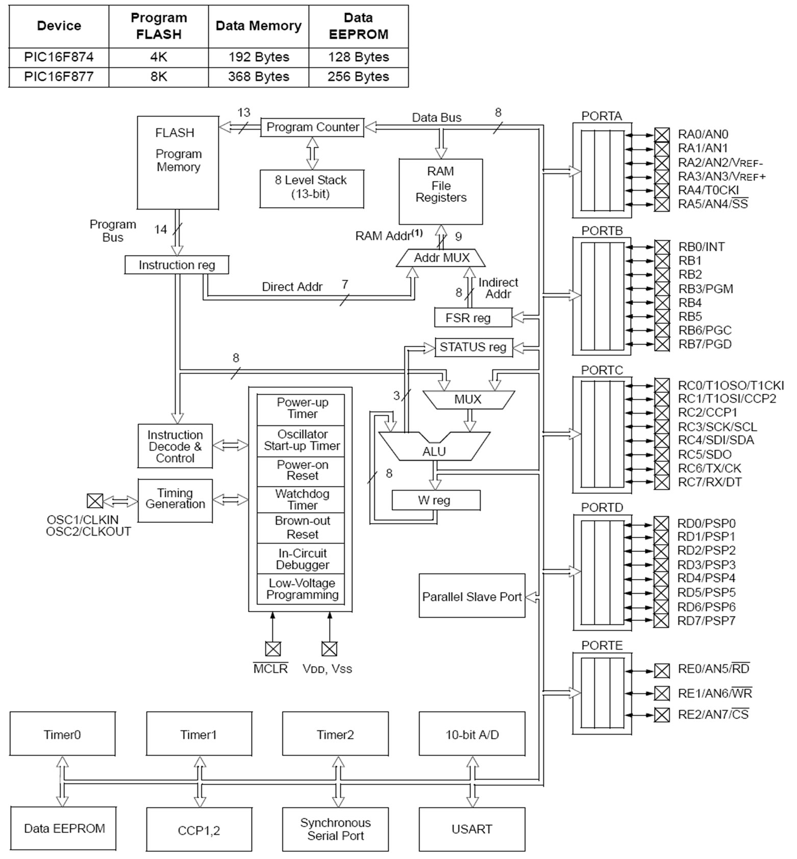
Figure 1. Microcontroller set [7].
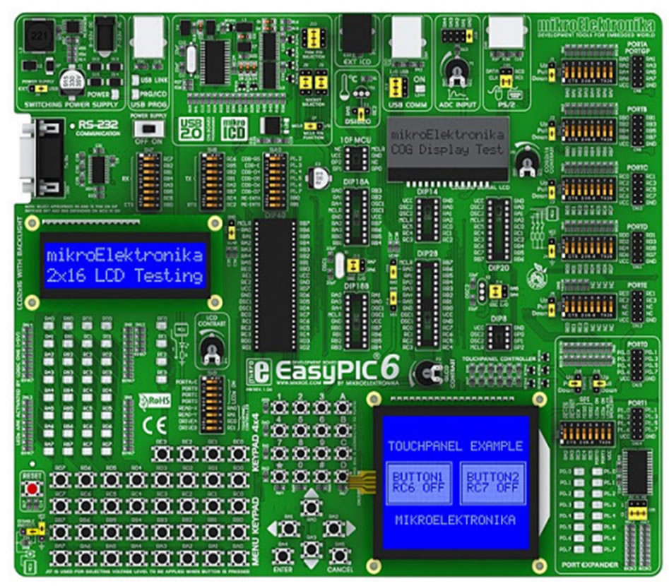
Figure 2. EasyPIC-6 cart by MikroElektronika [11].
so learning of new tool interface is minimized. These are the development capabilities of the MPLAB IDE:
Ø Source-code editing;
Ø Project management;
Ø Machine-code generation (from assembly or “C”);
Ø Device simulation;
Ø Device emulation;
Ø Device programming.
The comprehensive tool suite allows complete project development without leaving the MPLAB environment [12]. The MPLAB IDE software eases software development as never before in 8-bit microcontroller. MPLAB is a Windows application that contains:
o A full-features editor;
o Three operating modes:
■ Editor
■ Emulator
■ Simulator o A project manager;
o Extensive online help;
MPLAB allows o Editing of source files (ASM and C files);
o One-touch assembly (or compiling) and download to PIC16/17 tools;
o Debugging via:
■ Source files
■ Absolute listing file
■ Program memory o Run-up to four emulators on the same PC;
o Run or single-step;
■ Program memory
■ Source file
■ Absolute listing The microchip simulator, MPLAB-SIM, operates under the same platform as the PICMASTER emulator, so the user need only learn a single tool set that functions equally in both the simulator and the full-features emulator [13].
1.2. MPLAB-SIM Simulator Software
The software simulator is a no-cost tool for evaluating Microchip’s products and designs. Its use greatly helps debug software, particularly algorithms. Depending on a project’s design complexity, a time/cost benefit comparing simulator with emulator should be looked into. Projects with multiple development engineers can keep costs down by using both simulator and emulator, allowing speedy debugging of tough problems. MPLAB-SIM Simulator simulates PICmicro series microcontrollers at instruction level. With any given instruction, the user may examine or modify any of the data or provide external stimulus to any of the pins. The input/output radix can be set by the user, the execution performed as either single step, execute until break, or trace. MPLAB-SIM supports symbolic debugging via MPLAB-C and MPASM. The software simulator’s low-cost flexibility in developing and debugging code outside laboratory environment makes it excellent multi-project development tool [14,15].
PIC ranges very broadly, from tiny 6-pin 8-bit devices with just 16 bytes of data memory performing only basic digital I/O, to 100-pin 32-bit devices with 512 kilobytes of memory and many integrated peripherals for communications, data acquisition, and control. Newcomers may be confused by an aspect of PIC programming: the lowend devices have entirely separate addresses and data buses for data and program instructions. 8-bit or 16-bit refers to the amount of data that can be processed at once, i.e., the width of the data memory (in microchip terminology, “registers”) and the ALU (Arithmetic and Logic Unit). Low-end PICs, operating 8-bit data at any one time, have three architectural families [16,17].
1.2.1. Baseline (12-Bit Instructions)
These PICs are based on the original PIC architecture, going back to the 1970’s and General Instrument’s “Peripheral Interface Controller”. They are rather limited, but within their limits (such as no interrupts) are simple to work with (particularly in modern assemblers such as 6-pin 10F series, 8-pin 12F509, and 14-pin 16F506).
1.2.2. Midrange (14-Bit Instructions)
An extension of the baseline architecture, it supports interrupts, has more memory and on-chip timers and peripherals, includes PWM (pulse width modulation) for motor control, supports serial, I2C, and SPI interfaces, and has LCD controllers. Modern examples include 8-pin 12F629, 20-pin 16F690, and 40-pin 16F887.
1.2.3. High-End (16-Bit Instructions)
Otherwise known as 18F series, this architecture overcomes some limits of the midrange devices. It has more memory (up to 128k program memory and almost 4k data memory) and advanced peripherals (including USB, Ethernet, and CAN or controller area network) connectivity. The 18F architecture supports C programming and is, among 8-bit PIC families, the only one with C compiler. Examples include 18-pin 18F1220, 28-pin 18F2455, and 80-pin 18F8520. Maybe a little confusing is that PIC18F series has 16-bit program instructions operating on 8-bits of data at a time, and is considered an 8-bit chip [12,18].
BASIC programming language is known to users as the easiest and is the most used. The reputation is increasingly transferred onto microcontrollers. PIC BASIC enables quicker and relatively easier program writing for PIC microcontrollers, as compared with Microchip’s assembly language MPASM. During program writing, the programmer encounters the same problems always: serial sending of messages, writing of variable on LCD display, generating of six PWM signals, etc. [16].
Facilitating programming are PIC BASIC’s built-in commands, which are intended to solve problems typically found in praxis. Where execution speed and program size are concerned, MPASM is less advantaged than PIC BASIC (therefore giving rise to the possibility of combining PIC BASIC and assembler). The part of the program where the same commands are executed many times or the execution time is critical is usually written in assembler. Modern microcontrollers such as PIC execute the instructions in a single cycle lasting 4 tacts of the oscillator. If the microcontroller oscillator is 4 MHz (one tact lasts 250 nS), then one assembler instruction requires 250 nS × 4 = 1 uS for the execution. Each BASIC command is actually a sequence of assembler instructions; the exact time necessary for execution of a BASIC command is simply the sum of the times necessary for execution of assembler instructions within one BASIC command [17,19].
2. Hardware Design of the PIC Trainer Model
Figure 3 is a laboratory model of the trainer design hardware. The model has three main parts: board for applied experiments, PIC microcontroller simulator, and interfacing board with PC computer. There is also a built-in power supply.
2.1. Applied Experiments Board
The trainer can execute many experiments: electronic, control logic circuit, power system, etc. The main circuit connecting the board in standalone form will hereby be described. Sensor: the trainer has two types of sensors. One is an approximate sensor (model TURCK Bi14-cp23 APcx sn: 15 mm) detecting front iron paces with 15 mm accuracy and is the approximate switch. Another is photoelectric sensors (serial numbers BR56-DDT-P and BEN9M-TFR). Whereas the former detects interrupts within 5 m, the latter detects reflection two ways: normal closed or normal open. Relays: two types are used, i.e., two poles and three poles, with 24VDC and 24VDC/5A supplying the coils. Four 7-segment models are supplied by 5VDC/2A. Keypads: a matrix of LEDs, with matrix form through logic gates to run instructions of the (i, j) form. The matrix instructions are PIC-programmed and then entered as four rows and four columns. Conveyer belt: supplied by 5VDC/2A, displaying experiment outputs based on sensors or any other processes. DC Motor (model GMN-3M027A/DC24V): its circuit drive executes start/stop, opposite direction, and emergency shutdown instructions; each event is indicated by LEDs with shift rotating. See Figure 4 for the experiment board.
2.2. PIC Simulator Board and Interfacing
Five input ports (A→E) and two output ports (T0, T1). The ports transfer instructions and receive sensed signals from the experiment board. Every input/output signal on this board is LED-indicated for ON and OFF. The power supplies are 5VDC, 12VDC, and 24VDC. The PIC simulator is supplied first by the 5VDC and then by the USB cable through a PC. The experiment software is installed on-board via USB through the PIC simulator; another interface is RS232. Figure 5 shows the interfacing board.
3. Software Design of the PIC Trainer
This design uses BASIC language to implement the trainer’s experiments. After the program is written in mikroBasic, it is compiled to the PIC. The PC runs the BASIC
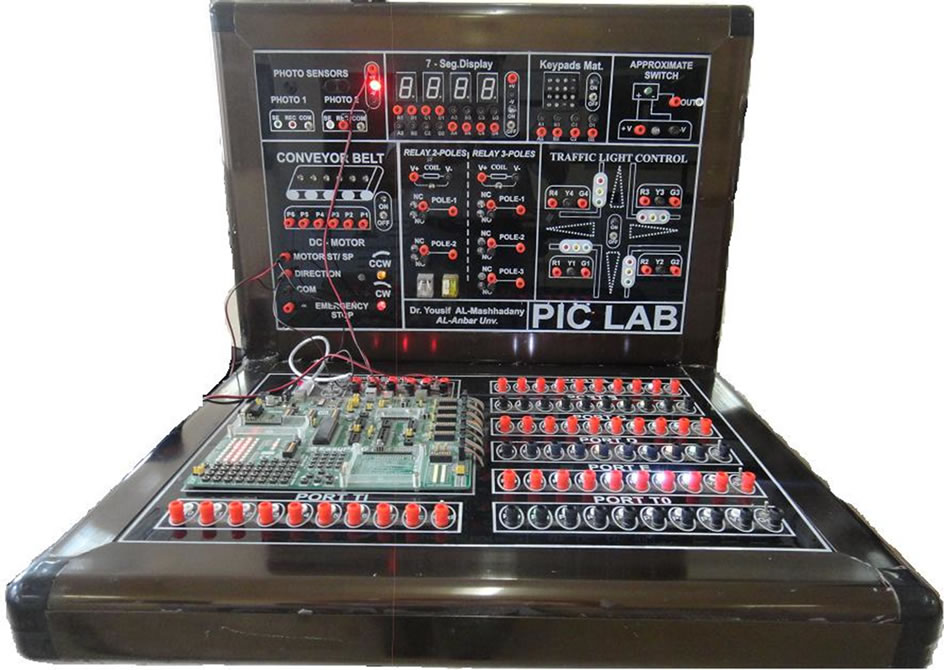
Figure 3. The PIC-microcontroller-based conventional electronic control trainer.
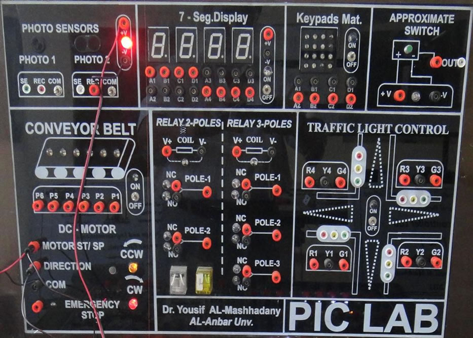
Figure 4. The experiment board.
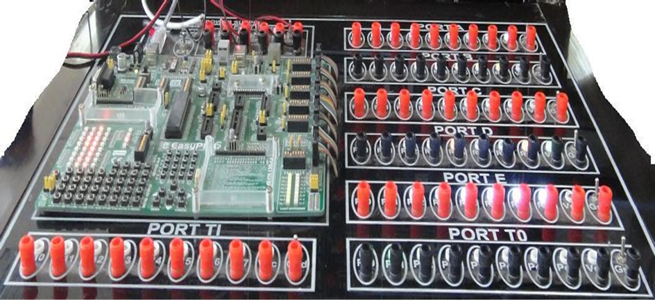
Figure 5. The interfacing board.
compiler program, which translates the original BASIC code into the language of 0s and 1s understood by the microcontroller. Figure 6 shows the translation of a BASIC program into an executive HEX code. The program, written in PIC BASIC and registered as Program.bas file, is converted into assembler code (Program.asm), which is further translated into executive HEX code written to the microcontroller memory by a programmer (a device transferring HEX files from the PC to the microcontroller’s memory). Each experiment has two procedures: one to write the PIC programming code by software, another
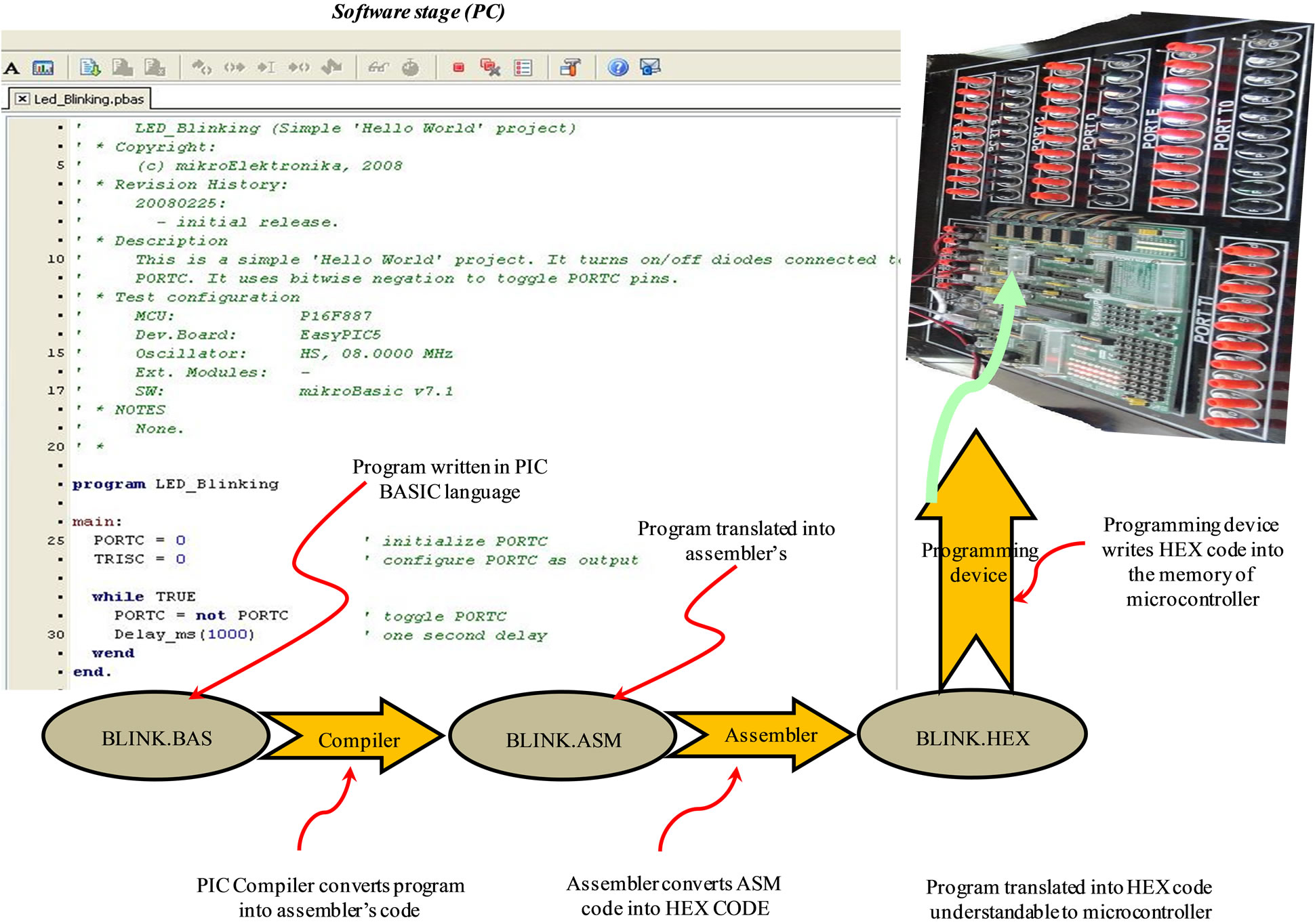
Figure 6. Details of the PIC trainer software.
to implement the hardware connection.
4. Case Study of the Trainer’s Use
The trainer was designed to implement experiments of various electrical engineering fields. It is capable of highlevel research projects and can be used in undergraduate laboratories. Two case studies, for power and electronic, are presented: DC motor controller and intelligent traffic light.
Controller for DC Motor: in the experiment, three main operations (start/stop, control of clockwise and anticlockwise directions, and emergency shutdown) are applied to a 24VDC motor (see Figure 7 for the drive circuit of the three operations). A 24VDC one-pole relay was used. The circuit could be manually controlled and could also use a PIC microcontroller to operate relay coil for executing a suitable instruction to the DC motor.
The experiment procedure is:
Ø Connect the board section (see Figure 8) to the three external power supplies on-board the microcontroller.
Ø Connect the other details to the microcontroller’s output pinnae.
Ø Write a program for the three experiment parts and set the program on a PIC chip (any serial, e.g., 16F- 667, 16F84A, etc.) and arrange for port A of the microcontroller to be the output.
Ø Feed the emergency inputs sensed by photoelectric sensor; manual feeding is possible as needed.
Ø Run the circuit by power ON of the voltage source and examine the instruction to the DC motor.
Ø The output must be present as the motor shift rotating and the corresponding LED lighting up showing the direction of rotation.
Intelligent Traffic Light: Optimal waiting time for traffic lights to change will reduce carbon monoxide emission, also save motorists’ time and reduce frustration. Other advantages are no interference between the sensor rays and no redundant signal triggering. Ability to interface with software allows this sensor-based traffic system to easily accept feedback (the software and the hardware can communicate). Table 1 lists the operation sequences.
The experiment procedure is:
Ø Connect the section of the board (see Figure 9) to output ports A and B of the microcontroller board.
Ø Write a program for the three parts of the experiment and set the program on the PIC chip (PIC 16F667) and arrange the output to be at ports A and B of the microcontroller.
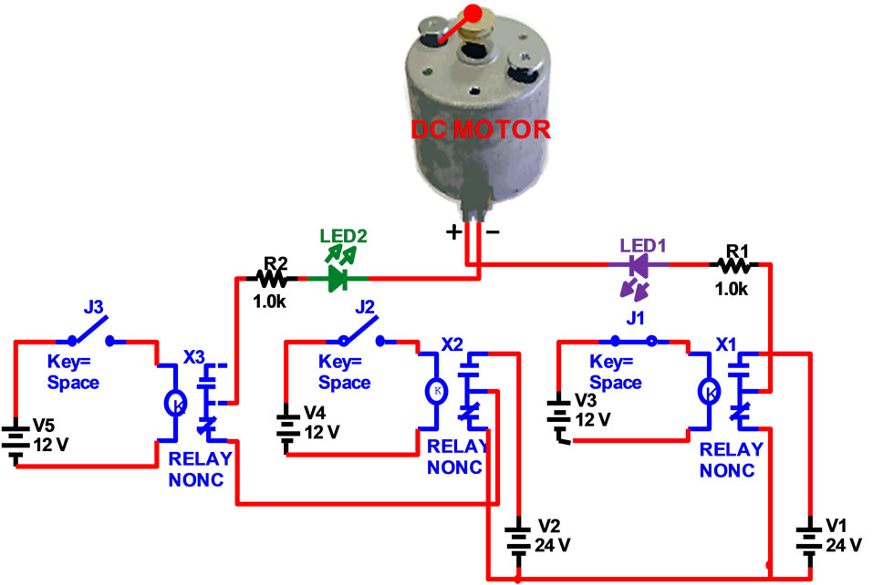
Figure 7. The drive circuit in the PIC controller experiment with the DC motor.
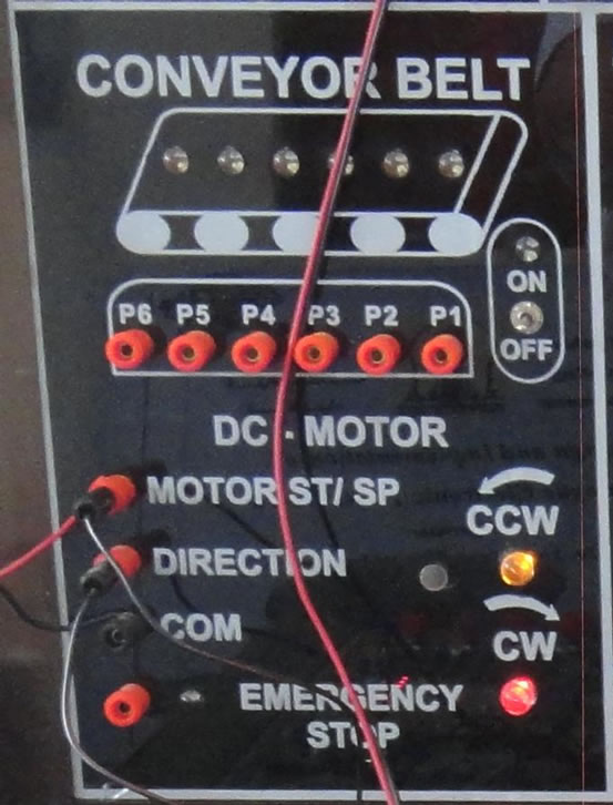
Figure 8. The DC motor section of the experiment.

Figure 9. Traffic light experiment schematic.
Ø Turn ON the power of the main board and then of the microcontroller board.
Ø Record the lighting time and sequence and compare with the program.
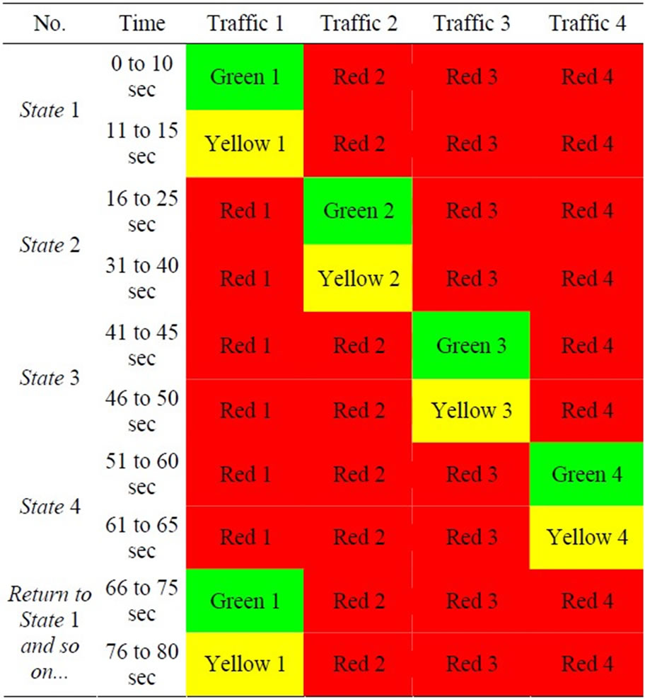
Table 1. Operation sequences of the intelligent traffic light.
Ø Investigate the effect of using photoelectric sensor signal; can it show what happens at a street intersection?
5. Conclusions
Results from practical implementation of all the experiments and simulation results from programming the PIC microcontroller board show the trainer to be very useful and necessary to many design plans. Its higher performance, lower cost, higher accuracy, and better speed response are all as compared with many types of classical trainers for electronic and control systems.
Its facilities will shorten the time taken for many design procedures (where applicable), simulations, and experiments; each can also be an individual system. The design enables instant initial results and modification of experiment steps such as setting the initial condition and updating some of the parameters, so the trainer’s accuracy and performance are increased.
The trainer allows practical simulations of many real systems. Capable of a wide range of experiments, it is very suitable for use in higher education laboratories. New experiments can be included by adding new circuits to the board and rearranging the connections.
6. Acknowledgements
Al Anbar University supported the project through manufacturing laboratory instruments funding. Al Sofa office provided help with consulting notes for the microcontroller’s practical application.
REFERENCES
- N. Barsoum, “Speed Control of the Induction Drive by Temperature and Light Sensors via PIC,” Transaction in Controllers and Drives, 2010, pp. 35-59.
- M. Bates, “Interfacing PIC Microcontrollers Embedded Design by Interactive Simulation,” Elsevier, Amsterdam, 2006.
- F. J. Diaz, F. J. Azcondo, R. Casanueva and C. Branas, “Microcontroller Software Applied to Electronic Ballast Design,” 13th European Conference on Power Electronics and Applications, Barcelona, 8-10 September 2009, pp. 1-8.
- H. W. Huang, “PIC Microcontroller: An Introduction to Software and Hardware Interfacing,” 2005. http://www.delmar.com.
- J. Main, “Measuring Resistance Using Digital I/O Using a Microcontroller for Measuring Resistance without Using an ADC,” 2008. http://www.best-microcontroller-projects.com
- C. Singh and K. Agarwal, “Design of Reactive PIC Microcontroller,” Proceedings of International Symposium on Signals, Systems and Electronics, Pilani, 17-20 September 2010, pp. 1-4.
- H. Rongen, “Introduction to PIC Microcontroller,” Forschungszentrum Jülich Zentrallabor für Elektronik, Jülich, 2009.
- N. Gardner, “An introduction to Programming the Microchip PIC in CCS C,” Ccs Inc., Christiansburg, 2002.
- B. Hossain, N. Hossain, M. Hossen and H. Rahman, “Design and Development of Microcontroller Based Electronic Queue Control Systems,” Proceeding of the 2011 IEEE Students’ Technology Symposium, Kharagpur, 14- 16 January 2011, pp. 48-52. doi:10.1109/TECHSYM.2011.5783862
- T. Wilmshurst, “Designing Embedded Systems with PIC Microcontrollers Principles and Applications,” Elsevier Ltd., New York, 2007.
- N. Matic and G. Maneger, “EasyPIC Microcontroller Board User Manual,” 2008.
- D. Ibrahim, “Advanced PIC Microcontroller Projects in C from USB to RTOS with the PIC18F Series,” Elsevier, Amsterdam, 2008.
- F. H. Fahmy, S. M. Sadek, N. M. Ahamed, M. B. Zahran, and A. El-S. A. Nafeh, “Microcontroller-Based Moving Message Display Powered by Photovoltaic Energy,” International Conference on Renewable Energies and Power Quality, Granada, 23-25 March 2010. http://www.icrepq.com/icrepq'10/726-Sadek.pdf
- Y. Aye, “Design and Construction of LAN Based Car Traffic Control System,” World Academy of Science, Engineering and Technology, Vol. 46, 2010, pp. 586-591.
- N. Matic, “BASIC for PIC Microcontrollers,” 2001. http://scalak.elektroda.eu/html/pliki/BasicforPICMicrocontrollers.pdf
- F. J. Díaz, F. J. Azcondo, R. Casanueva and Ch. Brañas, “Microcontroller Software Applied to Electronic Ballast Design,” University of Cantabria, Cantabria, 2010.
- S. C. Hsiung, “The Use of PIC Microcontrollers in Multiple DC Motors Control Applications,” Journal of Industrial Technology, Vol. 23, No. 3, 2007, pp. 2-3.
- S. Huseinbegovic and O. Tanovic, “Development of a Distributed Elevator Control System Based on the Microcontroller PIC 18F458,” 2010 IEEE Region 8 International Conference on Computational Technologies in Electrical and Electronics Engineering, Irkutsk, 11-15 July 2010, pp. 858-863.
- L. D. Jasio, et al., “PIC Microcontrollers,” Elsevier Inc., New York, 2008.
NOTES
*Implement a PIC Microcontroller as trainer at advance control laboratory.