Intelligent Control and Automation
Vol. 3 No. 2 (2012) , Article ID: 19236 , 8 pages DOI:10.4236/ica.2012.32015
Discrete Event Net Based Modeling and Control System Design for Real-Time Concurrent Control of Multiple Robot Systems
Department of Human and Computer Intelligence, Nagasaki Institute of Applied Science, Nagasaki, Japan
Email: yasuda_genichi@pilot.nias.ac.jp
Received January 8, 2012; revised March 2, 2012; accepted March 9, 2012
Keywords: Multiple Robot Systems; Concurrent Control; Control System Design; Net Models; Discrete Event Systems
ABSTRACT
This paper deals with control system design and implementation problems encountered in multiple robot systems. The methodology developed is depicted by a set of coordination mechanisms using hierarchical net structures and their accompanying rules. With the net models, the hierarchical and distributed control system is designed for an assembly task. Synchronization commands allow coordination of the movements of the robots. The net models make concurrency of the movements of the robots transparent to users. The net based machine controller executes robot motion control through the communication with the external robot controller using the command/response concept. Sensory signals indicating the change of state of robots are used to trigger or initiate tasks. Simultaneous movement of the robots is obtained by creating different background threads running in parallel under Windows OS. The multilevel hierarchical control system can be consistently constructed using net models.
1. Introduction
Recently, based on the rapid development of the microprocessor technology, the factory automation systems have been continuing to become more and more largescaled, complicated, and integrated. The two flows of control and data must be organized in the system, but to achieve it, system concept, system architecture, and system design method are not established sufficiently. Some techniques derived from Petri nets have been successfully introduced as an effective tool for representing control specifications including concurrent processes, which are characteristic of complex systems, analyzing system properties and designing control systems [1]. Especially, Petri nets are used to indicate the flow of control, and by decomposing the net, the concept of upper and lower control levels is clarified. The coordinator is defined as the agent which consistently executes the flow of control in the upper control level bringing about cooperation among the local machine controllers in the lower control level. The microprocessors seem to be the most suitable to realize the coordinator. They can be used to realize the coordinators corresponding to decomposed nets, besides the coordinator in the upper control level, using software directly on the same hardware.
The representation scheme of concurrent robotic activities as a decision logic structure is essential to control multiple robot systems that may be considered the most significant development in robotics fields [2-4]. The author presents a net based methodology for synthesizing complicated control software hierarchically for large and complex robotic systems, especially multiple robot systems. An algorithm is proposed for coordination of machine controllers so that robots can synchronize activities and avoid harmful conflicts. By the proposed method, highly reliable and efficient development of complicated real-time concurrent control algorithms for multiple robotic processes can be achieved.
2. Modeling of Discrete Event Robot Systems with Petri Nets
A Petri net comprises two types of nodes, places representing conditions (or states) and transitions representing events, which are interconnected by directed arcs [5]. Tokens, which reside at the places, are used to indicate the instantiation of a state. The current state of a net is represented by the distribution of tokens, or the marking, in the net. In a Petri net, the places, transitions and tokens are represented by the circles, bars and dots respectively. There are many forms of Petri net. The type considered here is the condition-event net in which each place can contain not more than one token. This allows a one-toone semantic correspondence between places and conditions.
Formally, a net is a bipartite graph represented by the 4-tuple 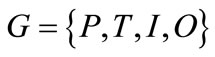 such that:
 is a finite set of places;
 is a finite set of transitions;
 is the input function that maps transitions to bags of places;
 is the output function that maps transitions to bags of places.
Thus the axioms of nets are as follows:
1) A transition is enabled, if and only if, each of its input places has one token and each of its output places has no token;
2) When an enabled transition fires, the marking is changed to the new one, where each of its input places has no token and each of output places has one token.
A transition without any input place is called a source transition, and one without any output place is called a sink transition. A source transition is unconditionally enabled, and the firing of a sink transition consumes a token in each input place but does not produce any. According to these axioms, the number of tokens in each place never exceeds one, thus, the net is essentially 1- bounded and said to be a safe graph.
In a net, a place represents a condition or state of a process or resource. A transition corresponds to an event or action. The input places of the transition define the conditions to the executions of the action. The output places define the results of the action. A token is placed in a place to indicate that the condition corresponding to the place is holding.
Conceptually, robotic processes are represented as sequential constructs or state machines, where each transition has exactly one incoming arc and exactly one outgoing arc. The structure of a place having two or more input or output transitions is referred to as a conflict, decision, or choice, depending on applications. State machines allow the representation of decisions, but not the synchronization of parallel activities.
The condition-event net is a subclass of Petri nets, so it can be represented by the ordinary Petri net [6]. Figures 1(a) and (b) illustrate a simple net and its equivalent net represented by the ordinary Petri net, which is achieved by addition of a place with the inversion of the existence of token and the directions of its input and output arcs, for each place of the net. The enabling rule for the ordinary Petri net, where all of its arc weights are 1, is that a transition is enabled, if and only if, each of its input places has more than one token.
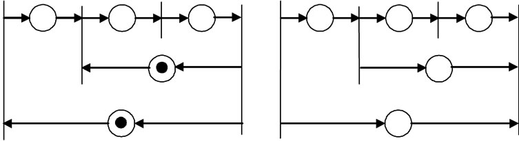
If there is no conflict place in a net, the net can be transformed to one with no loop, as shown in Figure 2. If there is a loop with no conflict place in a net, then the
 (a) (b)
Figure 1. (a) A simple net and (b) its equivalent Petri net.
 (a) (b)
Figure 2. (a) A net with no conflict place and (b) its equivalent net with no loop.
number of tokens in the loop is not changed.
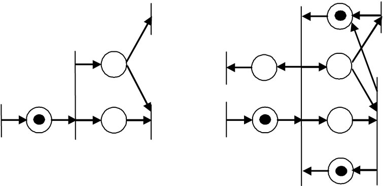
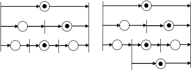
In case that there is initially no token in a net, if there is one token in a direct path between two transitions, then there is one token in one place in each of other paths between the transitions. Further, addition of a direct path in a path between the transitions does mot change the enabling conditions of the transitions in the net, as shown in Figures 3(a) and (b). Generally, if there are several concurrent paths in two transitions and if there is initially no token in the net, the maximum number of tokens in each path is the least number of places in the paths.
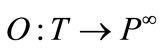
The condition-event net can be easily extended to adopt the following elements as input and output interfaces which connect the net to its environment: gate arcs and output arcs. A gate arc connects a transition with a status signal source, and depending on the signal, it either permits or inhibits the occurrence of the event. An output arc connects a place with an external machine and sends a command signal to the machine. These interfaces are represented by transitions which represent the communication activities of the net with its environment.
The places are connected via transitions, each having a boolean condition or gate condition. This condition is tested while the transition is enabled, i.e., when the preceding place is active. If the condition is true, the succeeding place becomes active, and the preceding place becomes inactive. Using gate arcs, an enabled transition fires when 1) it does not have any internal permissive arc signaling 0 nor any internal inhibitive arc signaling 1 and 2) it does not have any external permissive arc signaling 0 nor any external inhibitive arc signaling 1. Figure 4 illustrates place and gate variables involved in transition
 (a) (b)
Figure 3. (a) A net with direct path and (b) addition of dummy direct path.
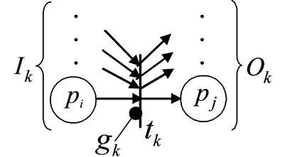
Figure 4. Place and gate variables involved in transition firing.
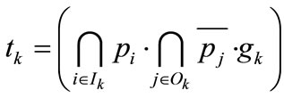
firing. The firing condition is expressed formally using logical variables as follows.
The logical variable  is set to 1 if a token is entered into the place, and reset to 0 if a token is removed from the place. The logical variable
  is set to 1 if the gate condition is 1 (i.e. permissive signal on), and reset to 0 if it is 0 (i.e. signal off). The logical variable
 ![]() is set to 1 if the transition is fired, and reset to 0 if it is not fired. Hence, from the above firing rules, the firing condition of transition
is set to 1 if the transition is fired, and reset to 0 if it is not fired. Hence, from the above firing rules, the firing condition of transition ![]() can be written as
can be written as
 (1)
(1)
where ![]() denotes the logical product operation, and
denotes the logical product operation, and
 : set of input places of transition
![]() .
.
 : set of output places of transition
![]() .
.
The marking change of input and output places of transition ![]() can be described as follows:
can be described as follows:
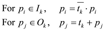 (2)
(2)
From Equation (1), by the inversion of the existence of token and the directions of its input and output arcs of a place, the enabling condition of every transition is not changed. Using the above procedure, if a net has no conflict place, the net can be transformed into a net with no loop.
The dynamic behavior of the system represented by a net model is simulated using the enabling and firing rules. One cycle of the simulation comprises the following two steps.
1) Calculate the logical variables of all transitions  using Equation (1).
2) Calculate the logical variables of all places 
 using Equation (2).
For efficient simulation combined with real-time control of a robotic system, the following steps are executed only when some gate condition is changed.
1) Calculate the logical variable of the transition associated with the new gate condition using Equation (1).
2) If the transition is fired, calculate the logical variables of its input and output places using Equation (2).
3) Then the marking is changed and a new command is sent to the corresponding machine.
Figure 5 shows the net representation of real-time control of a robotic unit action. When a token is placed in a place which represents an action, the net based controller initiates the execution of the action attached to the fired transition by sending the “start” signal through the output arc to the robot. Then the robot interprets the request and sends an acknowledgement to the controller. When the action is completed, the robot sends an “end” report to the controller.
Figure 6 shows a net with parallel processes and its decomposition into two subnets using permissive and inhibitive gate arcs. Shared transitions are decomposed and assigned to the subnets, which exchange the signals
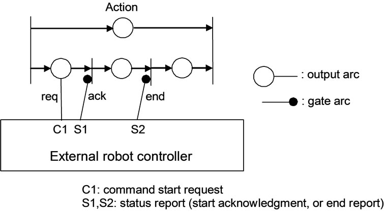
Figure 5. Net representation of execution of robotic action.
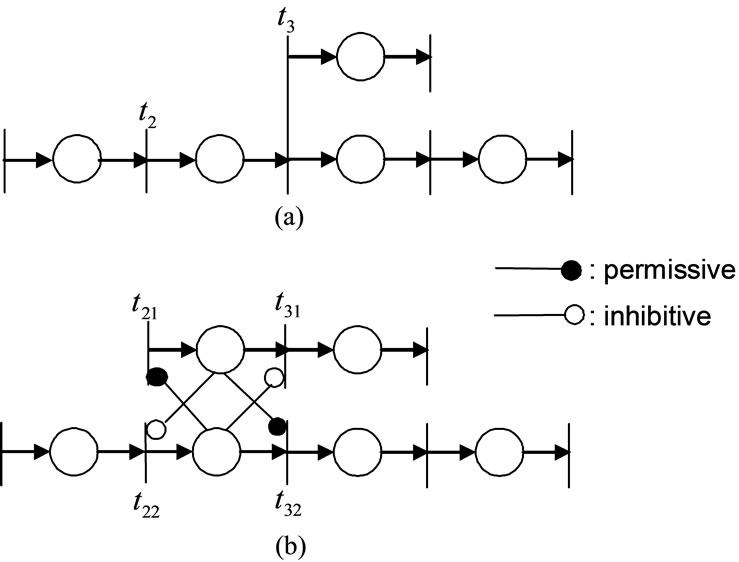
Figure 6. (a) A net with parallel processes and (b) its decomposition into two subnets.
corresponding to the state of the respective place.
3. Net Models of Hierarchical Coordination of Concurrent Robotic Tasks
The methodology addressed in this paper regards tasks to be performed by robots as being primal. A single task executed by a robot is represented as a state machine. Places for motion and computational actions have a unique output transition. Decision actions introduce conflict into the net. The choice can either be made non-deterministically or may be controlled by some external signal. In the case of two concurrent tasks, where each task can be represented by a net model of a state machine, the composite net which is simply the union of such nets can represent the concurrent execution of two tasks. Parallelism is usefully introduced into a system only if the component tasks can cooperate in the system. Such cooperation requires the sharing of information and resources between the tasks.
Figure 7 shows an example of hierarchical coordination of concurrent tasks by two robots. The constituent transitions t11 and t12 from transition t1 should be synchronized because they represent the same transition, so that the original transition is enabled if all transitions deriving for the distribution, called global transitions, are enabled.
In case that a transition in conflict with other transitions concerns two robots, if arbitration of the transition is performed independently in separate subnets, the results may be inconsistent with the original rule of arbitration. Figure 8 shows an example of hierarchical coordination of transitions in conflict. The transitions t1, t3 represent the start of independent tasks, while transition t2 represents the start of cooperative task. If both of the transitions t21 and t22 are enabled, transition t2 is enabled. Further if transitions t11 and t32 are enabled, then transitions t1, t2, t3 are enabled and should be arbitrated using some arbitration rule. If transition t2 is not enabled, the enabled transitions t1 and t3 can be fired. So transitions t11, t21, t22, t32 should be arbitrated together as a group. On the other hand, arbitration of local transitions in conflict is performed by local machine controllers.
4. Implementation of Concurrent Control System for Assembly Processes
A multiple robot system for robotic assembly operations has been constructed [7]. In the system, two small industrial robots are placed so that they share a common work space as shown in Figure 9. They are of the type Mitsubishi RM501, which has 5 degrees of freedom and close/open control of the gripper with its own built-in microprocessor control system. Each robot can be controlled by a general microcomputer which sends commands via a serial communication port. To direct a robot to move, the low-level command from the microcomputer must specify the number of steps that each joint of the robot arm must move. According to the physical dimensions, transformations were implemented to be used to calculate the joint steps to accomplish the desired move specified in the Cartesian coordinates. After completing each command, the robot sends an acknowledgement to the microcomputer. The syntax for the low-level commands as well as the protocols for sending and receiving data is specific to the robot.
Two robots cooperate with one another in building a
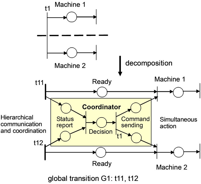
Figure 7. Hierarchical coordination of concurrent tasks.
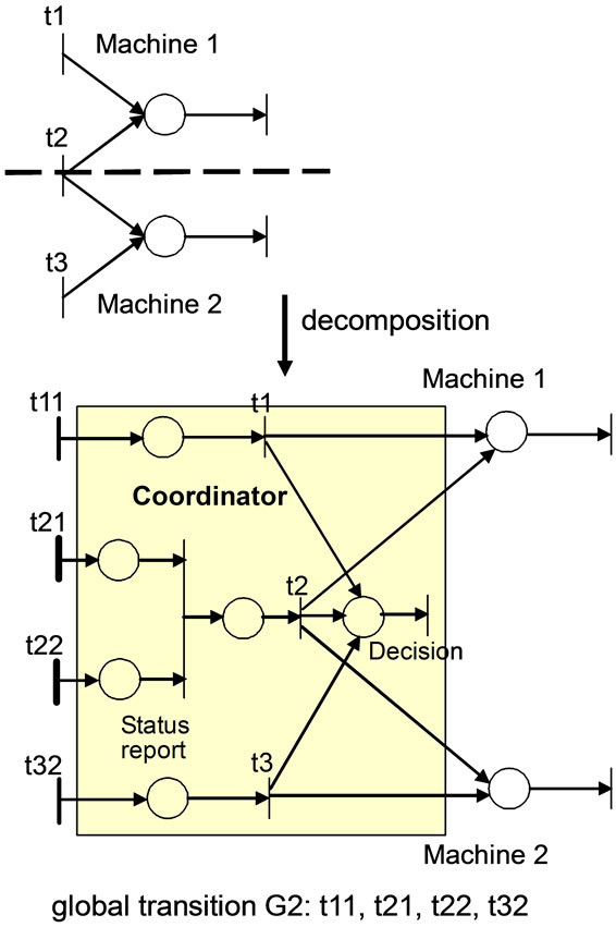
Figure 8. Hierarchical coordination of tasks in conflict.
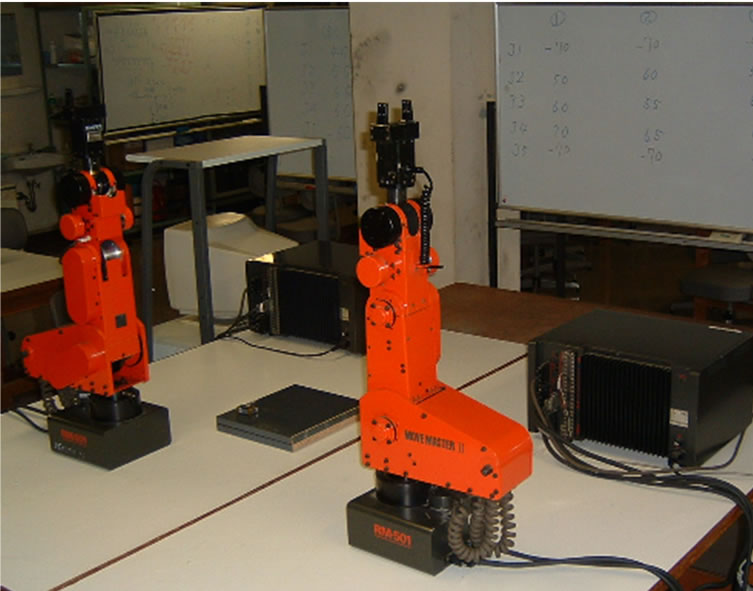
Figure 9. View of experimental robot system.
component, one holding some part while the other attaches some other part to it. The following items of information are required to generate task specification. 1) which parts are required for assembly, 2) connection relationship between parts when connected, 3) procedures for connecting parts, 4) initial and final positions of parts. The assembly process consists of two concurrent processes; main process and sub process which are assigned to Robot 1 and Robot 2 respectively. Figure 10 shows the conceptual net model of an example assembly task, which is specified using the following commands.
1) Part 1 is the basic part.
2) Part 2 is connected to part 1 (Part 2 + Part 1).
3) Connection of Part 4 and Part 3 starts after connection of Part 3 and Part 2 ends.
4) Part 7 and Part 2 (Part 8 and Part 4) must be connected together to connect Part 3 and Part 2 (Part 5 and Part 4).
Then, commands or subtasks are assigned to robots on the assumption that one part connection is one subtask. Subtasks in the main process must be executed sequentially and no overlap is permitted. There can be a wait status between subtasks. Part connections in sub process may be required for part connections in the main process. The end of the subtask in the main process is synchronized with the end of the global move of the subtask in the sub process. This causes the subtask in the main process to wait while the local move is executed in the sub process. When the subtask in the sub process ends, the next subtask in the main process starts. To synchronize complicated processes, several subtasks can be combined into one group subtask. If subtasks for robot 1 and robot 2 are described on the same transition, they are executed simultaneously, and the subtask on the next transition is not executed until they terminate.
The procedure for generation of motion of the robots is as follows. The layout of the robots is determined considering operational efficiency, and the work points are defined considering the positions of the robots. Then how the robots should move to the work points is determined taking the other robot’s location and the environment into consideration. Finally moving procedures and how the robots’ hands move between work points are determined. The local path is extracted from the connection information to separate the connected parts and connect one of them to other parts. The local path defined with respect to one of the part’s coordinate system is converted to world coordinates. A CAD based teaching system for multiple robots with 3D assembly modeler was developed to extract the items required for assembly, which are automatically translated into robotic task specification. Finally, coordinated robot motion is executed by a net based operation simulator.
As a prototype, system control software is implemented on a general PC using multithreaded programming [8]. Concurrent movement and coordination of the two robots in the system is obtained through four different background threads running in parallel. The control software consists of three different layers, each of which is executed by the respective thread: the system modeling thread, the system control thread, and the task execution thread, as shown in Figure 11. The system modeling thread contains the sequence of user commands for assembly task specification as well as the net modeling and drawing. For the example system, detailed net models can be automatically generated using the database of net models of general robotic operations. The thread is a core component which receives the states of all robots and machines in the system, and decides the next task. It then constructs the net model to be executed by the system control thread.
The system control thread contains system control commands for all the robots so as to accomplish a coordinated task. The thread also oversees the operation of a set of logically decentralized controllers. The coordination mechanism is implemented as a detailed representation of the original net, and the coordinator information is memorized in a table of the system controller and used to perform the net execution efficiently with the other tables representing the structure of the net specifying the
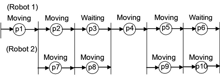
p1: Part 2 + Part 1; p2: Part 3 + Part 2; p7: Part 7 + Part 2 p4: Part 4 + Part 3; p5: Part 5 + Part 4; p9: Part 8 + Part 4
Figure 10. Net model of example assembly task.
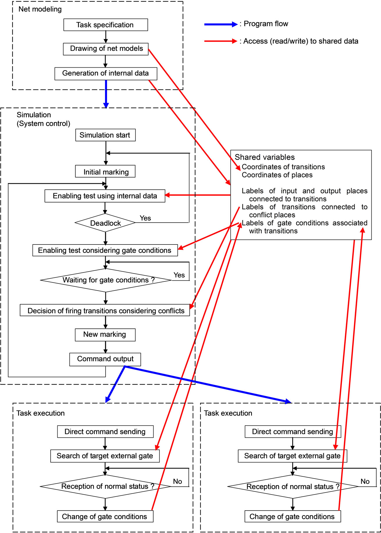
Figure 11. Software structure of distributed control system using multithreaded programming.
robotic task. Based on the coordination information, the system control program such as synchronization and arbitration can be written as production rules or IF-THEN expressions in the C language, such that rule conditions shown by a conjunctive form would, as a consequence, have a set of actions. In the hierarchical and distributed architecture composed of the system controller and several machine controllers [9], the enabling conditions of the global transitions are sent from each machine controller to the system controller, and the resulting actions are sent from the system controller to the machine controllers.
Task execution threads are created to perform the direct control of the robots. Each thread checks its queue for any records not executed yet. If the queue is empty, it suspends itself and waits for a new record. Whenever a new record is inserted, the thread wakes up immediately and resumes execution by processing the new record. After a high-level, system control command requiring robot interaction is read by the thread, the necessary calculations are performed and then the proper low-level command is sent to the robot. This robot first acknowledges that it has received the low-level command and later that it has finished executing the command. A thread waiting to read the acknowledgement from a robot waits in high priority and wakes up immediately when it arrives. Computations needed for the next robot command fill the gaps between I/O operations so that the control of the robots is accomplished very efficiently.
In addition to using pipes to communicate information between threads, other information is exchanged through shared memory. The database of net models of general robotic operations is created by the modeling thread and used by the system control thread. This shared memory also includes different flags used for mutual access control between the system control thread and the task execution threads. Coordination of mutual access among these threads was implemented through equivalent P and V semaphore operations in the following way. Each thread associates with it a flag in the shared file and a thread executes an equivalent P operation by decreasing the value of its flag. If this result is not negative, the thread continues. If this result is negative, the thread sleeps for a time and checks again.
Numerous simulations and real experiments using realized computer solutions indicate that the assembly task was realized satisfactorily; transitions in the detailed nets fire simultaneously as the transition in the conceptual net model of the whole system task. The control software provides concurrent movement of all the robots in the system, and it provides synchronization commands to allow coordination of their movements to accomplish user defined tasks. In contrast to decentralized implementation using synchronization mechanisms such as the WAIT and SIGNAL statements, synchronization can be easily implemented for several tasks by hierarchical coordination. The unique feature of the proposed method is that it provides modular software development for handling robots made by different manufacturers. By implementing the control software within a Windows XP SP3 and Visual C# environment, its extendability and transportability to other systems are ensured. Different robots can be interfaced to the system by simply adding specific motion procedures to the command library of net models. Transportability of the software was achieved by using the C language; it was transferred successfully to a microcomputer H8/3069 from Hitachi running the realtime OS ITRON 4. The performance of the control system using multithreaded programming depends on the operating system. If the task execution layer is implemented on a distributed microcomputer network connected via a serial bus [10,11], where each microcomputer is dedicated to the local net model of a robot or subsystem in the overall system, the performance of the distributed control system can be greatly improved.
5. Conclusions
A methodology of representing the interaction between robots and the interlock signals in multiple robot systems has been developed. The net models allow the user to visualize graphically the task programmed and the conditions required to initiate the constituent subtasks. Based on the hierarchical structure of Petri nets, hierarchical coordinator algorithms are designed to properly perform tasks that require the cooperation of two or more robots.
The coordination mechanism can be implemented in each layer repeatedly. The overall control system is consistently organized, such that for the coordinator in a layer the coordinator in one-level lower layer appears as the net based controller, and for the net based controller in a layer the net based controller in one-level upper layer appears as the coordinator. This means that the structure of the control system corresponds to the hierarchical and distributed structure of the robot system.
The net model is more general in comparison to the finite state machine model, because a changeover from one system state to the other is based on data from sensors and on information from lower levels. The solution is sufficiently cost-effective since the net model for system control is not so large and the detailed net models for robot control are state machines. These net models can be implemented on general PC, microcomputers or PLCs using conventional programming languages.
REFERENCES
- T. Murata, N. Komoda, K. Matsumoto and K. Haruna, “A Petri Net Based Controller for Flexible and Maintainable Sequence Control and Its Application in Factory Automation,” IEEE Transactions on Industrial Electronics, Vol. 33, No. 1, 1986, pp. 1-8. doi:10.1109/TIE.1986.351700
- R. Alur, J. Esposito, M. Kim, V. Kumar and I. Lee, “Formal Modeling and Analysis of Hybrid Systems—A Case Study in Multirobot Coordination,” Proceedings of the Wold Congress on Formal Methods in the Development of Computing Systems, Toulouse, September 20-24 1999, pp. 212-232.
- D. J. Holding and J. S. Sagoo, “A Formal Approach to the Software Control of High-Speed Machinery,” In G. W. Irwin and P. J. Fleming, Eds., Transputers in Real-Time Control, Research Studies Press, Somerset, 1992, pp. 239-282.
- P. J. Ramadge and W. M. Wonham, “Supervisory Control of a Class of Discrete Event Processes,” SIAM Journal on Control and Optimization, vol. 25, no.1, 1987, pp. 206- 230. doi:10.1137/0325013
- T. Murata, “Petri Nets: Properties, Analysis and Applications,” Proceedings of the IEEE, Vol. 77, No. 4, 1989, 541-580. doi:10.1109/5.24143
- K. Hasegawa, K. Takahashi, R. Masuda and H. Ohno, “Proposal of Mark Flow Graph for Discrete System Control,” Transactions of the Society of Instrument and Control Engineers, Vol. 20, No. 2, 1984, 122-129.
- G. Yasuda, “A Distributed Control and Communication Structure for Multiple Cooperating Robot Agents,” IFAC Artificial Intelligence in Real Time Control 2000, Budapest, 2-4 October 2000, pp. 283-288.
- G. Yasuda, “An Object-oriented Network Environment for Computer Vision Based Multirobot System Architectures,” Proceedings of 20th International Conference on Computers & Industrial Engineering, Kyongju, 6-9 October, 1996, pp. 1199-1202.
- G. Yasuda, “Implementation of Hierarchical and Distributed Control for Discrete Event Robotic Manufacturing Systems,” Journal of Software Engineering and Applications, Vol. 3, No. 5, 2010, pp. 436-445. doi:10.4236/jsea.2010.35049
- G. Yasuda and K. Tachibana, “A Parallel Distributed Control Architecture for Multiple Robot Systems Using a Network of Microcomputers,” Computers & Industrial Engineering, Vol. 27, No. 1-4, 1994, pp. 63-66. doi:10.1016/0360-8352(94)90238-0
- G. Yasuda and K. Tachibana, “A Computer Network Based Control Architecture for Autonomous Distributed Multirobot Systems,” Computers & Industrial Engineering, Vol. 31, No. 3-4, 1996, pp.697-702. doi:10.1016/S0360-8352(96)00232-X