Journal of Information Security
Vol.4 No.2(2013), Article ID:30057,12 pages DOI:10.4236/jis.2013.42010
Watermarking Images in the Frequency Domain by Exploiting Self-Inverting Permutations
Department of Computer Science, University of Ioannina, Ioannina, Greece
Email: mchroni@cs.uoi.gr, afylakis@cs.uoi.gr, stavros@cs.uoi.gr
Copyright © 2013 Maria Chroni et al. This is an open access article distributed under the Creative Commons Attribution License, which permits unrestricted use, distribution, and reproduction in any medium, provided the original work is properly cited.
Received January 25, 2013; revised February 27, 2013; accepted March 6, 2013
Keywords: Watermarking Techniques; Image Watermarking Algorithms; Self-Inverting Permutations; 2D Representations of Permutations; Encoding; Decoding; Frequency Domain; Experimental Evaluation
ABSTRACT
In this work we propose efficient codec algorithms for watermarking images that are intended for uploading on the web under intellectual property protection. Headed to this direction, we recently suggested a way in which an integer number w which being transformed into a self-inverting permutation, can be represented in a two dimensional (2D) object and thus, since images are 2D structures, we have proposed a watermarking algorithm that embeds marks on them using the 2D representation of w in the spatial domain. Based on the idea behind this technique, we now expand the usage of this concept by marking the image in the frequency domain. In particular, we propose a watermarking technique that also uses the 2D representation of self-inverting permutations and utilizes marking at specific areas thanks to partial modifications of the image’s Discrete Fourier Transform (DFT). Those modifications are made on the magnitude of specific frequency bands and they are the least possible additive information ensuring robustness and imperceptiveness. We have experimentally evaluated our algorithms using various images of different characteristics under JPEG compression. The experimental results show an improvement in comparison to the previously obtained results and they also depict the validity of our proposed codec algorithms.
1. Introduction
Internet technology, in modern communities, becomes day by day an indispensable tool for everyday life since most people use it on a regular basis and do many daily activities online [1]. This frequent use of the internet means that measures taken for internet security are indispensable since the web is not risk-free [2,3]. One of those risks is the fact that the web is an environment where intellectual property is under threat since a huge amount of public personal data is continuously transferred, and thus such data may end up on a user who falsely claims ownership.
It is without any doubt that images, apart from text, are the most frequent type of data that can be found on the internet. As digital images are a characteristic kind of intellectual material, people hesitate to upload and transfer them via the internet because of the ease of intercepting, copying and redistributing in their exact original form [4]. Encryption is not the problem’s solution in most cases, as most people that upload images in a website want them to be visible by everyone, but safe and theft protected as well. Watermarks are a solution to this problem as they enable someone to claim an image’s ownership if he previously embedded one in it. Image watermarks can be visible or not, but if we don’t want any cosmetic changes in an image then an invisible watermark should be used. That’s what our work suggests a technique according to which invisible watermarks are embedded into images using features of the image’s frequency domain and graph theory as well.
We next briefly describe the main idea behind the watermarking technique, the motivation of our work, and our contribution.
1.1. Watermarking
In general, watermarks are symbols which are placed into physical objects such as documents, photos, etc. and their purpose is to carry information about objects’ authenticity [5].
A digital watermark is a kind of marker embedded in a digital object such as image, audio, video, or software and, like a typical watermark, it is used to identify ownership of the copyright of such an object. Digital watermarking (or, hereafter, watermarking) is a technique for protecting the intellectual property of a digital object; the idea is simple: a unique marker, which is called watermark, is embedded into a digital object which may be used to verify its authenticity or the identity of its owners [6,7]. More precisely, watermarking can be described as the problem of embedding a watermark ![]() into an object
into an object  and, thus, producing a new object
 , such that
 ![]() can be reliably located and extracted from
can be reliably located and extracted from  even after
  has been subjected to transformations [7]; for example, compression, scaling or rotation in case where the object is an image.
In the image watermarking process the digital information, i.e., the watermark, is hidden in image data. The watermark is embedded into image’s data through the introduction of errors not detectable by human perception [8]; note that, if the image is copied or transferred through the internet then the watermark is also carried with the copy into the image’s new location.
1.2. Motivation
Intellectual property protection is one of the greatest concerns of internet users today. Digital images are considered a representative part of such properties so we consider important, the development of methods that deter malicious users from claiming others’ ownership, motivating internet users to feel safer to publish their work online.
Image Watermarking, is a technique that serves the purpose of image intellectual property protection ideally as in contrast with other techniques it allows images to be available to third internet users but simultaneously carry an “identity” that is actually the proof of ownership with them. This way image watermarking achieves its target of deterring copy and usage without permission of the owner. What is more by saying watermarking we don’t necessarily mean that we put a logo or a sign on the image as research is also done towards watermarks that are both invisible and robust.
Our work suggests a method of embedding a numerical watermark into the image’s structure in an invisible and robust way to specific transformations, such as JPEG compression.
1.3. Contribution
In this work we present an efficient and easily implemented technique for watermarking images that we are interested in uploading in the web and making them public online; this way web users are enabled to claim the ownership of their images.
What is important for our idea is the fact that it suggests a way in which an integer number can be represented with a two dimensional representation (or, for short, 2D representation). Thus, since images are two dimensional objects that representation can be efficiently marked on them resulting the watermarked images. In a similar way, such a 2D representation can be extracted for a watermarked image and converted back to the integer![]() .
.
Having designed an efficient method for encoding integers as self-inverting permutations, we propose an efficient algorithm for encoding a self-inverting permutation  into an image
  by first mapping the elements of
  into an
  matrix
  and then using the information stored in
  to mark specific areas of image
  in the frequency domain resulting the watermarked image
 . We also propose an efficient algorithm for extracting the embedded self-inverting permutation
  from the watermarked image
  by locating the positions of the marks in
 ; it enables us to recontract the 2D representation of the self-inverting permutation
 .
.
It is worth noting that although digital watermarking has made considerable progress and became a popular technique for copyright protection of multimedia information [8], our work proposes something new. We first point out that our watermarking method incorporates such properties which allow us to successfully extract the watermark ![]() from the image
from the image  even if the input image has been compressed with a lossy method. In addition, our embedding method can transform a watermark from a numerical form into a two dimensional (2D) representation and, since images are 2D structures, it can efficiently embed the 2D representation of the watermark by marking the high frequency bands of specific areas of an image. The key idea behind our extracting method is that it does not actually extract the embedded information instead it locates the marked areas reconstructing the watermark’s numerical value.
We have evaluated the embedding and extracting algorithms by testing them on various and different in characteristics images that were initially in JPEG format and we had positive results as the watermark was successfully extracted even if the image was converted back into JPEG format with various compression ratios. What is more, the method is open to extensions as the same method might be used with a different marking procedure such as the one we used in our previous work. Note that, all the algorithms have been developed and tested in MATLAB [9].
1.4. Road Map
The paper is organized as follows. In Section 2 we present an efficient transformation of a watermark from an integer form to a two dimensional (2D) representation through the exploitation of self-inverting permutation properties. In Section 3 we briefly describe the main idea behind our recently proposed image watermarking algorithm, while in Section 4 we present our contribution with this paper. In Section 5 we show properties of our image watermarking technique and evaluate the performance of the corresponding watermarking algorithms. Section 6 concludes the paper and discusses possible future extensions.
2. Theoretical Framework
In this section we first describe discrete structures, namely, permutations and self-inverting permutations, and briefly discuss a codec system which encodes an integer number ![]() into a self-inverting permutation
into a self-inverting permutation![]() . Then, we present a transformation of a watermark from a numerical form to a 2D form (i.e., 2D representation) through the exploitation of self-inverting permutation properties.
. Then, we present a transformation of a watermark from a numerical form to a 2D form (i.e., 2D representation) through the exploitation of self-inverting permutation properties.
2.1. Self-Inverting Permutations
Informally, a permutation of a set of objects ![]() is an arrangement of those objects into a particular order, while in a formal (mathematical) way a permutation of a set of objects
is an arrangement of those objects into a particular order, while in a formal (mathematical) way a permutation of a set of objects ![]() is defined as a bijection from
is defined as a bijection from ![]() to itself (i.e., a map
to itself (i.e., a map  for which every element of
 ![]() occurs exactly once as image value).
occurs exactly once as image value).
Permutations may be represented in many ways. The most straightforward is simply a rearrangement of the elements of the set ; in this way we think of the permutation
  as a rearrangement of the elements of the set
  such that “1 goes to 5”, “2 goes to 6”, “3 goes to 9”, “4 goes to 8”, and so on [10,11]. Hereafter, we shall say that
 ![]() is a permutation over the set
is a permutation over the set .
.
Definition: Let  be a permutation over the set
 , where
 . The inverse of the permutation
 ![]() is the permutation
is the permutation  with
with . A self-inverting permutation (or, for short, SiP) is a permutation that is its own inverse:
 .
.
By definition, a permutation is a SiP (self-inverting permutation) if and only if all its cycles are of length 1 or 2; for example, the permutation  is a SiP with cycles: (1,5), (2,6), (3,9), (4,8), and (7).
2.2. Encoding Numbers as SiPs
There are several systems that correspond integer numbers into permutations or self-inverting permutation [10]. Recently, we have proposed algorithms for such a system which efficiently encodes an integer ![]() into a self-inverting permutations
into a self-inverting permutations ![]() and efficiently decodes it. The algorithms of our codec system run in
and efficiently decodes it. The algorithms of our codec system run in  time, where
 ![]() is the length of the binary representation of the integer
is the length of the binary representation of the integer![]() , while the key-idea behind its algorithms is mainly based on mathematical objects, namely, bitonic permutations [12].
, while the key-idea behind its algorithms is mainly based on mathematical objects, namely, bitonic permutations [12].
We briefly describe below our codec algorithms which in fact correspond integer numbers into self-inverting permutations; we show the correspondence between the integer  and the self-inverting permutation
  by the help of an example.
Example W-to-SiP: Let  be the given watermark integer. We first compute the binary representation
  of the number 12; then we construct the binary number
  and the binary sequence
  by flipping the elements of
 ; we compute the sequences
  and
and  by taking into account the indices of 0s and 1s in
 , and then the bitonic permutation
  on
on  numbers by taking the sequence
 ; since
  is odd, we select 4 cycles
 ,
,  ,
,  ,
,  of lengths 2 and one cycle
  of length 1, and then based on the selected cycles construct the self-inverting permutation
 .
.
Example SiP-to-W: Let  be the given self-inverting permutation produced by our method. The cycle representation of
 ![]() is the following: (1,5), (2.6), (3,9), (4,8), (7); from the cycles we construct the permutation
is the following: (1,5), (2.6), (3,9), (4,8), (7); from the cycles we construct the permutation ; then, we compute the first increasing subsequence
  and the first decreasing subsequence
 ; we then construct the binary sequence
 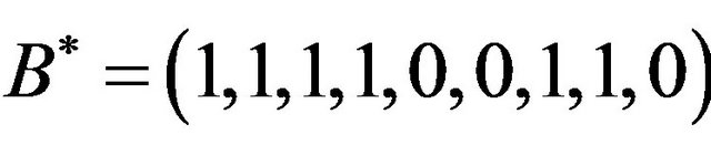 of length 9; we flip the elements of
  and construct the sequence
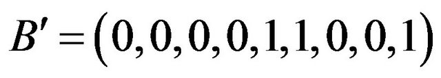 ; the binary number 1100 is the integer
 .
.
2.3. 2D Representations
We first define the two-dimensional representation (2D representation) of a permutation ![]() over the set
over the set , and then its 2DM representation which is more suitable for efficient use in our codec system.
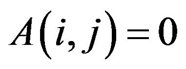
In the 2D representation, the elements of the permutation  are mapped in specific cells of an
 ![]() matrix
matrix  as follows:
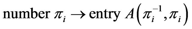
or, equivalently, the cell at row  and column
  is labeled by the number
 , for each
 .
.
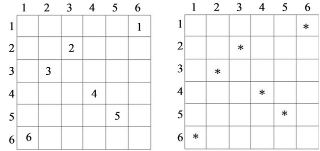
Figure 1(a) shows the 2D representation of the selfinverting permutation .
.
Note that, there is one label in each row and in each column, so each cell in the matrix  corresponds to a unique pair of labels; see, [10] for a long bibliography on permutation representations and also in [13] for a DAG representation.
Based on the previously defined 2D representation of a permutation![]() , we next propose a two-dimensional marked representation (2DM representation) of
, we next propose a two-dimensional marked representation (2DM representation) of ![]() which is an efficient tool for watermarking images.
which is an efficient tool for watermarking images.
In our 2DM representation, a permutation ![]() over the set Nn is represented by an
over the set Nn is represented by an ![]() matrix
matrix  as follows:
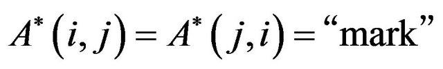
• the cell at row  and column
  is marked by a specific symbol, for each
 ;
;
• in our implementation, the used symbol is the asterisk, i.e., the character “*”.
Figure 1(b) shows the 2DM representation of the permutation![]() . It is easy to see that, since the 2DM representation of
. It is easy to see that, since the 2DM representation of ![]() is constructed from the corresponding 2D representation, there is also one symbol in each row and in each column of the matrix
is constructed from the corresponding 2D representation, there is also one symbol in each row and in each column of the matrix .
.
We next present an algorithm which extracts the permutation ![]() from its 2DM representation matrix. More precisely, let
from its 2DM representation matrix. More precisely, let ![]() be a permutation over
be a permutation over  and let
  be the 2DM representation matrix of
 ![]() (see, Figure 1(b)); given the matrix
(see, Figure 1(b)); given the matrix , we can easily extract
 ![]() from
from  in linear time (i.e., linear in the size of matrix
 ) by the following algorithm:
Algorithm Extract_![]() _from_2DM Input: the 2DM representation matrix
_from_2DM Input: the 2DM representation matrix  of
of![]() ;
;
Output: the permutation![]() ;
;
Step 1: For each row  of matrix
 ,
,  , and for each column
  of matrix
 ,
,  , if the cell
  is marked then
 ;
;
Step 2: Return the permutation![]() ;
;
Remark 1. It is easy to see that the resulting permutation![]() , after the execution of Step 1, can be taken by reading the matrix
, after the execution of Step 1, can be taken by reading the matrix  from top row to bottom row and write down the positions of its marked cells. Since the permutation
 ![]() is a self-inverting permutation, its 2D matrix
is a self-inverting permutation, its 2D matrix  has the following property:
•  if
if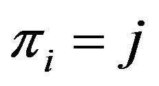 , and
, and
•  otherwise,
 .
.
Thus, the corresponding matrix  is symmetric:
•  if
if , and
, and
 (a) (b)
Figure 1. The 2D and 2DM representations of the self-inverting permutation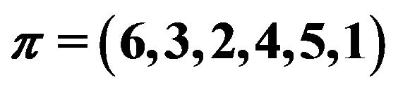 .
.
•  otherwise,
 .
.
Based on this property, it is also easy to see that the resulting permutation ![]() can be also taken by reading the matrix
can be also taken by reading the matrix  from left column to right column and write down the positions of its marked cells.
Hereafter, we shall denote by  a SiP and by
  the number of elements of
 .
.
2.4. The Discrete Fourier Transform
The Discrete Fourier Transform (DFT) is used to decompose an image into its sine and cosine components. The output of the transformation represents the image in the frequency domain, while the input image is the spatial domain equivalent. In the image’s fourier representation, each point represents a particular frequency contained in the image’s spatial domain.
If  is an image of size
  we use the following formula for the Discrete Fourier Transform:
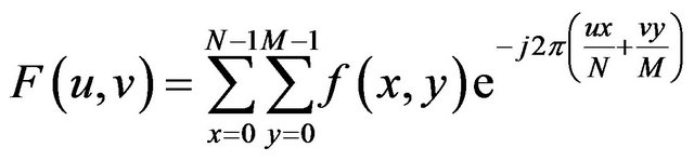 (1)
(1)
for values of the discrete variables ![]() and
and ![]() in the ranges
in the ranges  and
and .
.
In a similar manner, if we have the transform  i.e the image’s fourier representation we can use the Inverse Fourier Transform to get back the image
  using the following formula:
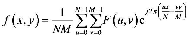 (2)
(2)
for  and
and .
.
Typically, in our method, we are interested in the magnitudes of DFT coefficients. The magnitude  of the Fourier transform at a point is how much frequency content there is and is calculated by Equation (1) [14].
3. Previous Results
Recently, we proposed a watermarking technique based on the idea of interfering with the image’s pixel values in the spatial domain. In this section, we briefly describe the main idea of the proposed technique and state main points regarding some of its advantages and disadvantages. Recall that, in the current work we suggest an expansion to this idea by moving from the spatial domain to the image’s frequency domain.
3.1. Method Description
The algorithms behind the previously proposed technique were briefly based on the following idea.
The embedding algorithm first computes the 2DM representation of the permutation , that is, the
  array
array  (see, Subsection 2.3); the entry
  of the array
  contains the symbol “*”,
 .
.
Next, the algorithm computes the size  of the input image
  and according to its size, covers it with an
  imaginary grid
 , which divides the image into
 grid-cells
  of size
 ,
, .
.
Then the algorithm goes first to each grid-cell , locates its central pixel
  and also the four pixels
 ,
,  ,
,  ,
,  around it,
  (these five pixels are called cross pixels), and then computes the difference between the brightness of the central pixel
  and the average brightness of twelve neighboring pixels around the cross pixels, and stores the resulting value in the variable dif
 . Finally, it computes the maximum absolute value of all
  differences dif
 ,
,  , and stores it in the variable Maxdif
 .
.
The embedding algorithm goes again to each central pixel  of each grid-cell
 ,
,  , and if the corresponding entry
  contains the symbol “*”, then it increases the value of each one of the five cross pixels by Maxdif
 – dif
– dif  +
+![]() , where
, where ![]() is a positive number used to make marks robust to transformations.
is a positive number used to make marks robust to transformations.
In a similar manner, the extracting algorithm is searching each line  of the imaginary grid
  to find among the
  grid-cells
  the column
  of the one that has the greatest difference between the twelve neighboring and the five cross pixels,
 ; then, the element
  is set equal to
 .
.
3.2. Main Points
First we should mention that for images with general characteristics and relatively large size this method delivers optically good results. By saying “good results” we mean that the modifications made are quite invisible. Also the method’s algorithms run really fast as they simply access a finite number of pixels. Furthermore, both the embedding and extracting algorithms are easy to modify and adjust for various scenarios.
On the other hand, the method fails to deliver good results either for relatively small images or for images that depict something smooth which allows the eye to distinct the modifications on the image. Also we decided to move to a new method as there were also problems due to the fact that the positions of the crosses are centered at strictly specific positions causing difficulties in the extracting algorithm even for the smallest geometric changes such as scaling or cropping where we may lose the marked positions.
4. The Frequency Domain Approach
Having described an efficient method for encoding integers as self-inverting permutations using the 2DM representation of self-inverting permutations, we next describe codec algorithms that efficiently encode and decode a watermark into the image’s frequency domain [14-17].
4.1. Embed Watermark into Image
We next describe the embedding algorithm of our proposed technique which encodes a self-inverting permutation (SiP)  into a digital image
 . Recall that, the permutation
  is obtained over the set
 , where
  and
and ![]() is the length of the binary representation of an integer
is the length of the binary representation of an integer ![]() which actually is the image’s watermark [12]; see, Subsection 2.2.
which actually is the image’s watermark [12]; see, Subsection 2.2.
The watermark![]() , or equivalently the self-inverting permutation
, or equivalently the self-inverting permutation , is invisible and it is inserted in the frequency domain of specific areas of the image
 . More precisely, we mark the DFT’s magnitude of an image’s area using two ellipsoidal annuli, denoted hereafter as “Red” and “Blue” (see, Figure 2). The ellipsoidal annuli are specified by the following parameters:
•  , the width of the “Red” ellipsoidal annulus•
  , the width of the “Blue” ellipsoidal annulus•
  and
and , the radiuses of the “Red” ellipsoidal annulus on y-axis and x-axis, respectively.
The algorithm takes as input a SiP  and a digital image
 , in which the user embeds the watermark, and returns the watermarked image
 ; it consists of the following steps.
Algorithm Embed_SiP-to-Image Input: the watermark  and the host image
 ;
;
Output: the watermarked image ;
;
Step 1: Compute first the 2DM representation of the permutation , i.e., construct an array
  of size
  such that the entry
  contains the symbol “*”,
 .
.
Step 2: Next, calculate the size  of the input image
  and cover it with an imaginary grid
  with
with
 grid-cells
  of size
 ,
, .
.
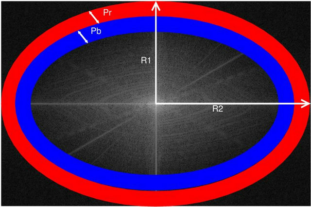
Figure 2. The “Red” and “Blue” ellipsoidal annuli.
Step 3: For each grid-cell , compute the Discrete Fourier Transform (DFT) using the Fast Fourier Transform (FFT) algorithm, resulting in a
  grid of DFT cells
 ,
, .
.
Step 4: For each DFT cell , compute its magnitude
  and phase
  matrices which are both of size
 ,
, .
.
Step 5: Then, the algorithm takes each of the  magnitude matrices
 ,
,  , and places two imaginary ellipsoidal annuli, denoted as “Red” and “Blue”, in the matrix
  (see, Figure 2). In our implementation• the “Red” is the outer ellipsoidal annulus while the “Blue” is the inner one. Both are concentric at the center of the
  magnitude matrix and have widths
  and
and , respectively;
• the radiuses of the “Red” ellipsoidal annulus are  (on the y-axis) and
  (on the
 ![]() -axis), while the “Blue” ellipsoidal annulus radiuses are computed in accordance to the “Red” ellipsoidal annulus and have values
-axis), while the “Blue” ellipsoidal annulus radiuses are computed in accordance to the “Red” ellipsoidal annulus and have values  and
and , respectively;
• the inner perimeter of the “Red” ellipsoidal annulus coincides to the outer perimeter of the “Blue” ellipsoidal annulus;
• the values of the widths of the two ellipsoidal annuli are  and
and , while the values of their radiuses are
  and
and .
.
The areas covered by the “Red” and the “Blue” ellipsoidal annuli determine two groups of magnitude values on  (see, Figure 2).
Step 6: For each magnitude matrix ,
,  , compute the average of the values that are in the areas covered by the “Red” and the “Blue” ellipsoidal annuli; let
  be the average of the magnitude values belonging to the “Red” ellipsoidal annulus and
  be the one of the “Blue” ellipsoidal annulus.
Step 7: For each magnitude matrix ,
,  , compute first the variable
  as follows:
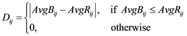 .
.
Then, for each row  of the magnitude matrix
 ,
,  , compute the maximum value of the variables
  in row
 ; let
; let  be the max value.
Step 8: For each cell  of the 2DM representation matrix
  of the permutation
  such that
  “*” (i.e., marked cell), mark the corresponding grid-cell
 ,
, ; the marking is performed by increasing all the values in magnitude matrix
  covered by the “Red” ellipsoidal annulus by the value
 (3)
(3)
where . The additive value of
  is calculated by the function
  (see, Subsection 4.3) which returns the minimum possible value of
 ![]() that enables successful extracting.
that enables successful extracting.
Step 9: Reconstruct the DFT of the corresponding modified magnitude matrices , using the trigonometric form formula [14], and then perform the Inverse Fast Fourier Transform (IFFT) for each marked cell
 ,
,  , in order to obtain the image
 .
.
Step 10: Return the watermarked image .
.
In Figure 3, we demonstrate the main operations performed by our embedding algorithm. In particular, we show the marking process of the grid-cell  of the Lena image; in this example, we embed in the Lena image the watermark number
 ![]() which corresponds to SiP
which corresponds to SiP .
.
4.2. Extract Watermark from Image
In this section we describe the decoding algorithm of our proposed technique. The algorithm extracts a self-
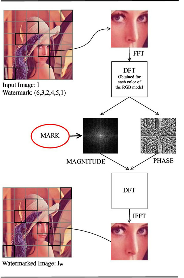
Figure 3. A flow of the embedding process.
inverting permutation (SiP)  from a watermarked digital image
 , which can be later represented as an integer
![]() .
.
The self-inverting permutation  is obtained from the frequency domain of specific areas of the watermarked image
 . More precisely, using the same two “Red” and “Blue” ellipsoidal annuli, we detect certain areas of the watermarked image
  that are marked by our embedding algorithm and these marked areas enable us to obtain the 2D representation of the permutation
 . The extracting algorithm works as follows:
Algorithm Extract_SiP-from-Image Input: the watermarked image  marked with
 ;
;
Output: the watermark ;
;
Step 1: Take the input watermarked image  and calculate its
  size. Then, cover it with the same imaginary grid
 , as described in the embedding methodhaving
  grid-cells
  of size
 .
.
Step 2: Then, again for each grid-cell ,
,  , using the Fast Fourier Transform (FFT) get the Discrete Fourier Transform (DFT) resulting a
  grid of DFT cells.
Step 3: For each DFT cell, compute its magnitude matrix  and phase matrix
  which are both of size
 .
.
Step 4: For each magnitude matrix , place the same imaginary “Red” and “Blue” ellipsoidal annuli, as described in the embedding method, and compute as before the average values that coincide in the area covered by the “Red” and the “Blue” ellipsoidal annuli; let
  and
and  be these values.
Step 5: For each row  of
of ,
,  , search for the
  column where
  is minimized and set
 ,
, .
.
Step 6: Return the self-inverting permutation .
.
Having presented the embedding and extracting algorithms, let us next describe the function  which returns the additive value
  (see, Step 8 of the embedding algorithm Embed_SiP-to-Image).
4.3. Function f
Based on our marking model, the embedding algorithm amplifies the marks in the “Red” ellipsoidal annulus by adding the output of the function . What exactly
  does is returning the optimal value that allows the extracting algorithm under the current requirements, such as JPEG compression, to still be able to extract the watermark from the image.
The function  takes as an input the characteristics of the image and the parameters
 ,
,  ,
,  , and
, and  of our proposed marking model (see, Step 5 of embedding algorithm and Figure 2), and returns the minimum possible value
  that added as
 ![]() to the values of the “Red” ellipsoidal annulus enables extracting (see, Step 8 of the embedding algorithm). More precisely, the function
to the values of the “Red” ellipsoidal annulus enables extracting (see, Step 8 of the embedding algorithm). More precisely, the function  initially takes the interval
 , where
  is a relatively great value such that if
  is taken as
 ![]() for marking the “Red” ellipsoidal annulus it allows extracting, and computes the
for marking the “Red” ellipsoidal annulus it allows extracting, and computes the  in
in .
.
Note that,  allows extracting but because of being great damages the quality of the image (see, Figure 4). We mentioned relatively great because it depends on the characteristics of each image. For a specific image it is useless to use a
  greater than a specific value, we only need a value that definitely enables the extracting algorithm to successfully extract the watermark.
We next describe the computation of the value  returned by the function
 ; note that, the parameters
  and
and  of our implementation are fixed with the values 2 and 2, respectively. The main steps of this computation are the following:
(1) Check if the extracting algorithm for  validly obtains the watermark
  from the image
 ; if yes, then the function
  returns
 ;
;
(2) If not, that means,  doesn’t allow extracting; then, the function
  uses binary search on
  and computes the interval
  such that:
•  doesn’t allow extracting•
  does allow extracting, and
•  ;
;
(3) The function  returns
 ;
;
As mentioned before, the function  returns the optimal value
 . Recall that, optimal means that it is the smallest possible value which enables extracting
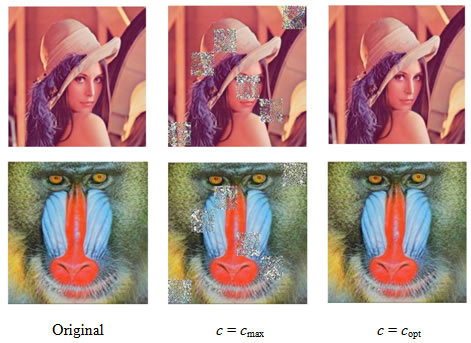
Figure 4. The original images of Lena and Baboon followed by their watermarked images with different additive values c, i.e., the optimal value and a relatively large value c; both images are marked with the same watermark (6,3,2,4,5,1).
from the image . It is important to be the smallest one as that minimizes the additive information to the image and, thus, assures minimum drop to the image quality.
5. Experimental Evaluation
In this section we present the experimental results of the proposed watermarking method which we have implemented using the general-purpose mathematical software package Matlab (version 7.7.0) [9].
We experimentally evaluated our codec algorithms on digital color images of various sizes and quality characteristics. Many of the images in our image repository where taken from a web image gallery [18] and enriched by some other images different in sizes and characteristics. Our experimental evaluation is based on two objective image quality assessment metrics namely Peak Signal to Noise Ratio (PSNR) and Structural Similarity Index Metric (SSIM) [19].
There are three main requirements of digital watermarking: fidelity, robustness, and capacity [5]. Our watermarking method appears to have high fidelity and robustness against JPEG compression.
5.1. Design Issues
We tested our codec algorithms on various 24-bit digital color images of various sizes (from  up to
up to ) and various quality characteristics.
In our implementation we set both of the parameters  and
and  equal to 2; see, Subsection 4.1. Recall that, the value 2 is a relatively small value which allows us to modify a satisfactory number of values in order to embed the watermark and successfully extract it without affecting images’ quality. There isn’t a distance between the two ellipsoidal annuli as that enables the algorithm to apply a small additive information to the values of the “Red” annulus. The two ellipsoidal annuli are inscribed to the rectangle magnitude matrix, as we want to mark images’ cells on the high frequency bands.
We mark the high frequencies by increasing their values using mainly the additive parameter  because alterations in the high frequencies are less detectable by human eye [20]. Moreover, in high frequencies most images contain less information.
In this work we used JPEG images due to their great importance on the web. In addition, they are small in size, while storing full color information (24 bit/pixel), and can be easily and efficiently transmitted. Moreover, robustness to lossy compression is an important issue when dealing with image authentication. Notice that the design goal of lossy compression systems is opposed to that of watermark embedding systems. The Human Visual System model (HVS) of the compression system attempts to identify and discard perceptually insignificant information of the image, whereas the goal of the watermarking system is to embed the watermark information without altering the visual perception of the image [21].
The quality factor (or, for short,  factor) is a number that determines the degree of loss in the compression process when saving an image. In general, JPEG recommends a quality factor of 75 - 95 for visually indistinguishable quality loss, and a quality factor of 50 - 75 for merely acceptable quality. We compressed the images with Matlab JPEG compressor from imwrite with different quality factors; we present results for
 ,
,  and
and .
.
The quality function  returns the factor c, which has the minimum value
  that allows the extracting algorithm to successfully extract the watermark. In fact, this value
  is the main additive information embedded into the image; see, formula (3). Depending on the images and the amount of compression, we need to increase the watermark strength by increasing the factor
![]() . Thus, for the tested images we compute the appropriate values for the parameters of the quality function
. Thus, for the tested images we compute the appropriate values for the parameters of the quality function ; this computation can be efficiently done by using the algorithm described in Subsection 4.3.
To demonstrate the differences on watermarked image human visual quality, with respect to the values of the additive factor![]() , we watermarked the original images Lena and Baboon and we embedded in each image the same watermark with
, we watermarked the original images Lena and Baboon and we embedded in each image the same watermark with  and
and , where
 ; the results are demonstrated in Figure 4.
5.2. Image Quality Assessment
In order to evaluate the watermarked image quality obtained from our proposed watermarking method we used two objective image quality assessment metrics, that is, the Peak Signal to Noise Ratio (PSNR) and the Structural Similarity Index Metric (SSIM). Our aim was to prove that the watermarked image is closely related to the original (image fidelity), because watermarking should not introduce visible distortions in the original image as that would reduce images’ commercial value.
The PSNR metric is the ratio of the reference signal and the distortion signal (i.e., the watermark) in an image given in decibels (dB); PSNR is most commonly used as a measure of quality of reconstruction of lossy compression codecs (e.g., for image compression). The higher the PSNR value the closer the distorted image is to the original or the better the watermark conceals. It is a popular metric due to its simplicity, although it is well known that this distortion metric is not absolutely correlated with human vision.
For an initial image  of size
  and its watermarked image
 , PSNR is defined by the formula:
 (4)
(4)
where  is the maximum signal value that exists in the original image and MSE is the Mean Square Error given by
 (5)
(5)
The SSIM image quality metric [19] is considered to be correlated with the quality perception of the HVS [22]. The SSIM metric is defined as follows:
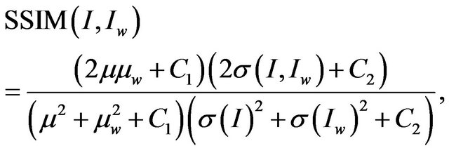 (6)
(6)
where  and
and  are the mean luminances of the original and watermarked image
  respectively,
  is the standard deviation of
 ,
,  is the standard deviation of
 , whereas
  and
and  are constants to avoid null denominator. We use a mean SSIM (MSSIM) index to evaluate the overall image quality over the
  sliding windows; it is given by the following formula:
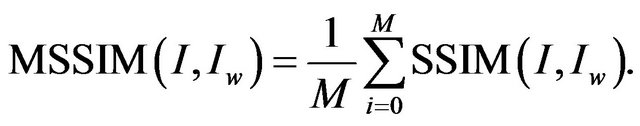 (7)
(7)
The highest value of SSIM is 1, and it is achieved when the original and watermarked images, that is,  and
and , are identical.
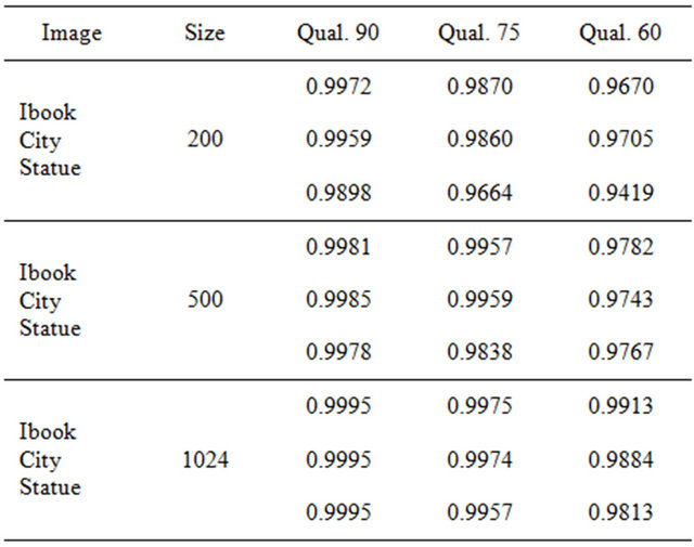
Our watermarked images have excellent PSNR and SSIM values. In Figure 5, we present three images of different sizes, along with their corresponding PSNR and SSIM values. Typical values for the PSNR in lossy image compression are between 40 and 70 dB, where higher is better. In our experiments, the PSNR values of  of the watermarked images were greater than 40 dB. The SSIM values are almost equal to 1, which means that the watermarked image is quite similar to the original one, which proves the method’s high fidelity.
In Tables 1 and 2, we demonstrate the PSNR and SSIM values of some selected images of various sizes used in our experiments. We observe that both values, PSNR and SSIM, decrease as the quality factor of the images becomes smaller. Moreover, the additive value ![]() that enables robust marking under qualities
that enables robust marking under qualities  and 60 does not result in a significant image distortion as Tables 1 and 2 suggest; see also the watermarked images on Figure 5.
In closing, we mention that Lena and Baboon images of Figure 4 are both of size . Lena image has PSNR values 55.4, 50.1, 46.2 and SSIM values 0.9980, 0.9934, 0.9854 for
 , respectively, while Baboon image has PSNR values 52.7, 46.2, 42.5
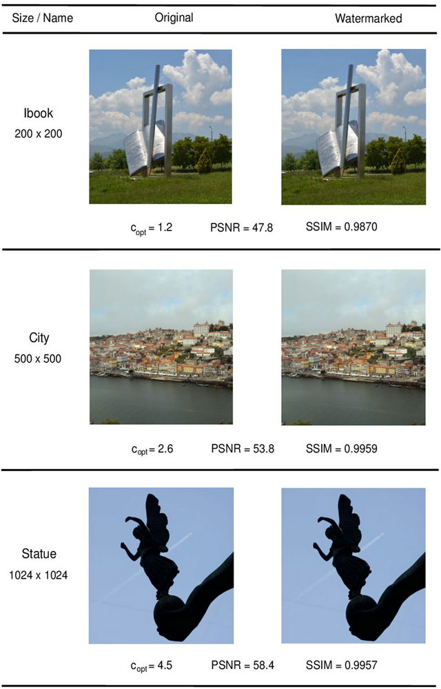
Figure 5. Sample images of three size groups for JPEG quality factor  and their corresponding watermarked ones; for each image, the c, PSNR and SSIM values are also shown.
Table 1. The PSNR values of watermarked images of different sizes under JPEG qualities .
.
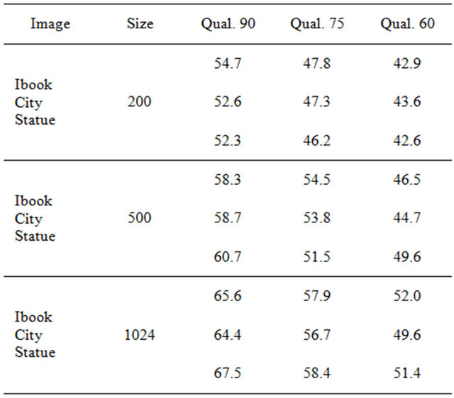
Table 2. The SSIM values of watermarked images of different sizes under JPEG qualities .
.
and SSIM values 0.9978, 0.9908, 0.9807 for the same quality factors.
5.3. Other Experimental Outcomes
In the following, based on our experimental results, we discuss several impacts concerning characteristics of the host images and our embedding algorithm, and also we justify them by providing explanations on the observed outcomes.
5.3.1. The Additive Value Influences
As the experimental results show the PSNR and SSIM values decrease after embedding the watermark in images with lower quality index in its JPEG compression; see, Tables 1 and 2. That happens since our embedding algorithm adds more information in the frequency of marked image parts. By more information we mean a greater additive factor![]() ; see, Equation (3).
; see, Equation (3).
We next discuss an important issue concerning the additive value  returned by function
 ; see, Subsection 4.3. In Table 3, we show a sample of our results demonstrating for each JPEG quality the respective values of the additive factor
 . The figures show that the
  value increases as the quality factor of JPEG compression decreases. It is obvious that the embedding algorithm is image dependent. It is worth noting that
  values are small for images of relatively small size while they increase as we move to images of greater size.
Moving beyond the sample images in order to show the behaviour of additive value  under different image sizes, we demonstrate in Figure 6 the average
  values of all the tested images grouped in three different sizes. We decided to select three representative groups for small, medium, and large image sizes, that is, 200 × 200, 500 × 500 and 1024 × 1024, respectively. For each size group we computed the average
  under the JPEG quality factors
 .
.
As the experimental results suggest the embedding process requires greater optimal values  for the additive variable
 ![]() as we get to JPEG compressions with lower qualities. The reason for that can be found looking at the three main steps of JPEG compression:
as we get to JPEG compressions with lower qualities. The reason for that can be found looking at the three main steps of JPEG compression:
1) In the first step, the image is separated into ![]() blocks and converted to a frequency-domain representation, using a normalized, two-dimensional discrete cosine transform (DCT) [23].
blocks and converted to a frequency-domain representation, using a normalized, two-dimensional discrete cosine transform (DCT) [23].
2) Then, quantization of the DCT coefficients takes place. This is done by simply dividing each component of the DCT coefficients matrix by the corresponding constant from the same sized Quantization matrix, and then rounding to the nearest integer.
3) In the third step, it’s entropy coding which involves arranging the image components in a “zigzag” order employing run-length encoding (RLE) algorithm that groups
Table 3. The optimal c values for watermarking image samples with respect to JPEG qualities .
.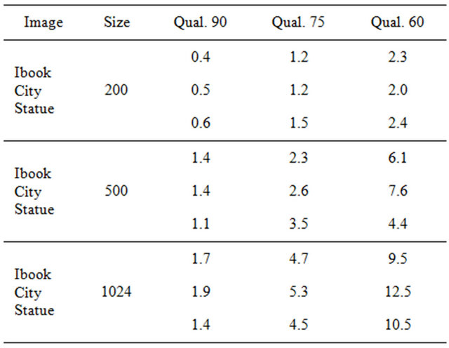
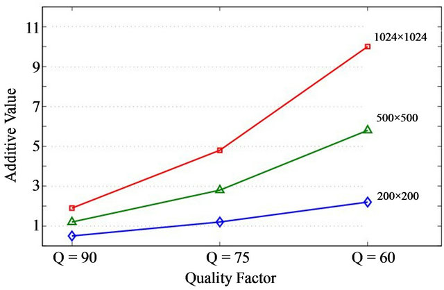
Figure 6. The average optimal c values for the tested images grouped in three deferent sizes under the JPEG quality factors .
.
similar frequencies together, inserting length coding zeros, and then using Huffman coding on what is left.
Focusing on the second step, we should point out that images with higher compression (lower quality) make use of a Quantization matrix which typically has greater values corresponding to higher frequencies meaning that information for high frequency is greatly reduced as it is less perceivable by human eye.
As we mentioned our method marks images in the higher frequency domain which means that as the compression ratio increases marks gradually become weaker and thus  increases to strengthen the marks.
Furthermore, someone may notice that  also increases for larger images. That is because regardless of the image size the widths of the ellipsoidal annuli remain the same meaning that the larger the image the less frequency amplitude is covered by the constant sized annuli. That makes marks less robust and require a greater
  to strengthen them.
5.3.2. Frequency Domain Imperceptiveness
It is worth noting that the marks made to embed the watermark in the image are not just invisible in the image itself but they are also invisible in the image’s overall Discrete Fourier Transform (DFT). More precisely, if someone suspects the existence of the watermark in the frequency domain and gets the image’s DFT, it is impossible to detect something unusual. This is also demonstrated in Figure 7, which shows that in contrast with using the ellipsoidal marks in the whole image, using them in specific areas makes the overall DFT seem normal.
6. Concluding Remarks
In this paper we propose a method for embedding invisible watermarks into images and their intention is to prove the authenticity of an image. The watermarks are given
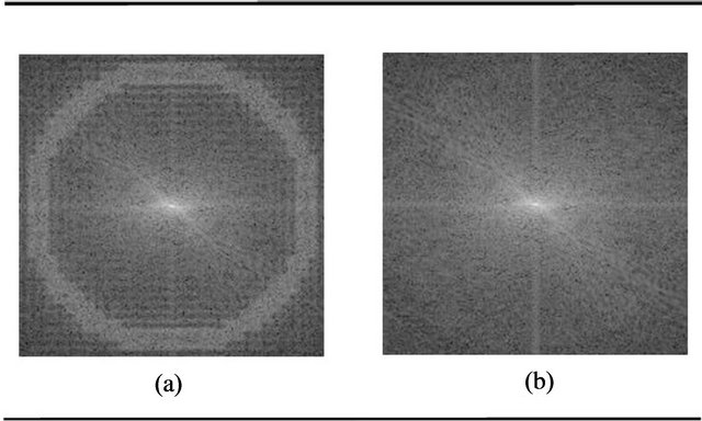
Figure 7. (a) The DFT of a watermarked image marked on the full image’s frequency domain. (b) The DFT of a watermarked image marked partially with our technique.
in numerical form, transformed into self-inverting permutations, and embedded into an image by partially marking the image in the frequency domain; more precisely, thanks to 2D representation of self-inverting permutations, we locate specific areas of the image and modify their magnitude of high frequency bands by adding the least possible information ensuring robustness and imperceptiveness.
We experimentally tested our embedding and extracting algorithms on color JPEG images with various and different characteristics; we obtained positive results as the watermarks were invisible, they didn’t affect the images’ quality and they were extractable despite the JPEG compression. In addition, the experimental results show an improvement in comparison to the previously obtained results and they also depict the validity of our proposed codec algorithms.
It is worth noting that the proposed algorithms are robust against cropping or rotation attacks since the watermarks are in SiP form, meaning that they determine the embedding positions in specific image areas. Thus, if a part is being cropped or the image is rotated, SiP’s symmetry property may allow us to reconstruct the watermark. Furthermore, our codec algorithms can also be modified in the future to get robust against scaling attacks. That can be achieved by selecting multiple widths concerning the ellipsoidal annuli depending on the size of the input image.
Finally, we should point out that the study of our quality function  remains a problem for further investigation; indeed,
  could incorporate learning algorithms [24] so that to be able to return the
  accurately and in a very short computational time.
REFERENCES
- S. Garfinkel, “Web Security, Privacy and Commerce,” 2nd Edition, O’Reilly, Sebastopol, 2001.
- L. Chun-Shien, H. Shih-Kun, S. Chwen-Jye and M. L. Hong-Yuan, “Cocktail Watermarking for Digital Image Protection,” IEEE Transactions on Multimedia, Vol. 2, No. 4, 2000, pp. 209-224. doi:10.1109/6046.890056
- J. C. Davis, “Intellectual Property in Cyberspace—What Technological/Legislative Tools are Necessary for Building a Sturdy Global Information Infrastructure?” Proceedings of the IEEE International Symposium on Technology and Society, Glasgow, 20-21 June 1997, pp. 66- 74.
- J. J. K. O’Ruanaidh, W. J. Dowling and F. M. Boland, “Watermarking Digital Images for Copyright Protection,” Proceedings of the IEE Vision, Image and Signal Processing, Vol. 143, No. 4, 1996, pp. 250-256. doi:10.1049/ip-vis:19960711
- I. J. Cox, M. L. Miller, J. A. Bloom, J. Fridrich and T. Kalker, “Digital Watermarking and Steganography,” 2nd Edition, Morgan Kaufmann, Burlington, 2008.
- D. Grover, “The Protection of Computer Software—Its Technology and Applications,” Cambridge University Press, New York, 1997.
- C. Collberg and J. Nagra, “Surreptitious Software,” Addison-Wesley, Boston, 2010.
- I. Cox, J. Kilian, T. Leighton and T. Shamoon, “A Secure, Robust Watermark for Multimedia,” Proccedings of the 1st International Workshop on Information Hiding, Vol. 1174, 1996, pp. 317-333.
- R. C. Gonzalez, R. E. Woods and S. L. Eddins, “Digital Image Processing Using Matlab,” Prentice-Hall, Upper Saddle River, 2003.
- R. Sedgewick and P. Flajolet, “An Introduction to the Analysis of Algorithms,” Addison-Wesley, Boston, 1996.
- M. C. Golumbic, “Algorithmic Graph Theory and Perfect Graphs,” Academic Press Inc., New York, 1980.
- M. Chroni and S. D. Nikolopoulos, “Encoding Watermark Integers as Self-Inverting Permutations,” Proccedings of the 11th International Conference on Computer Systems and Technologies, ACM ICPS 471, 2010, pp. 125-130.
- M. Chroni and S. D. Nikolopoulos, “An Efficient Graph Codec System for Software Watermarking,” Proceedings of the 36th International Conference on Computers, Software, and Applications, Workshop STPSA’12, 2012, pp. 595-600.
- R. C. Gonzalez and R. E. Woods, “Digital Image Processing,” 3rd Edition, Prentice-Hall, Upper Saddle River, 2007.
- V. Solachidis and I. Pitas, “Circularly Symmetric Watermark Embedding in 2D DFT Domain,” IEEE Transactions on Image Processing, Vol. 10, No. 11, 2001, pp. 1741-1753. doi:10.1109/83.967401
- V. Licks and R. Hordan, “On Digital Image Watermarking Robust to Geometric Transformations,” Proceedings of the IEEE International Conference on Image Proceesing, Vol. 3, 2000, pp. 690-693.
- E. Ganic, S. D. Dexter and A. M. Eskicioglu, “Embedding Multiple Watermarks in the DFT Domain Using Low and High Frequency Bands,” Proceedings of Security, Steganography, and Watermarking of Multimedia Contents VII, Jan Jose, 17 January 2005, pp. 175-184. doi:10.1117/12.594697
- F. Petitcolas, “Image Database for Watermarking,” September 2012. http://www.petitcolas.net/fabien/watermarking/
- Z. Wang, A. C. Bovic, H. R. Sheikh and E. P. Simoncelli, “Image Quaity Assessment: From Error Visibility to Structural Similarity,” IEEE Transactions on Image Processing, Vol. 13, No. 4, 2004, pp. 600-612. doi:10.1109/TIP.2003.819861
- M. Kaur, S. Jindal and S. Behal, “A Study of Digital Image Watermarking,” Journal of Research in Engineering and Applied Sciences, Vol. 2, No. 2, 2012, pp. 126-136.
- J. M. Zain, “Strict Authentication Watermarking with JPEG Compression (SAW-JPEG) for Medical Images for Medical Images,” European Journal of Scientific Research, Vol. 42, No. 2, 2010, pp. 250-256.
- A. Hore and D. Ziou, “Image Quality Metrics: PSNR vs. SSIM,” Proceedings of the 20th International Conference on Pattern Recognition, Istanbul, 2010, pp. 2366-2369.
- N. Ahmed, T. Natarajan and K. R. Rao, “Discrete Cosine Transform,” IEEE Transactions on Computers, Vol. 23, No. 1, 1974, pp. 90-93. doi:10.1109/T-C.1974.223784
- S. Russell and P. Norvig, “Artificial Intelligence: A Modern Approach,” 3rd Edition, Prentice-Hall, Upper Saddle River, 2010.