Materials Sciences and Applications
Vol.09 No.11(2018), Article ID:88039,17 pages
10.4236/msa.2018.911064
Complex Permittivity and Permeability Studies Viewing Antenna Applications of NBR-Based Composites Comprising Conductive Fillers
Abdullah G. Al-Sehemi1,2, Ahmed A. Al-Ghamdi3, Nikolay T. Dishovsky4, Nikolay T. Atanasov5,6, Gabriela L. Atanasova5,6
1Research Center for Advanced Materials Science (RCAMS), King Khalid University, Abha, KSA
2Department of Chemistry, College of Science, King Khalid University, Abha, KSA
3Department of Physics, Faculty of Science, King Abdulaziz University, Jeddah, KSA
4Department of Polymer Engineering, University of Chemical Technology and Metallurgy, Sofia, Bulgaria
5Department of Telecommunications, Faculty of Telecommunications and Management, University of Telecommunications and Post, Sofia, Bulgaria
6Department of Communication and Computer Engineering, Faculty of Engineering, South-West University “Neofit Rilski”, Blagoevgrad, Bulgaria

Copyright © 2018 by authors and Scientific Research Publishing Inc.
This work is licensed under the Creative Commons Attribution International License (CC BY 4.0).
http://creativecommons.org/licenses/by/4.0/


Received: September 10, 2018; Accepted: October 23, 2018; Published: October 26, 2018
ABSTRACT
The work presents studies on the complex permittivity and permeability of composites based on acrylonitrile butadiene rubber containing combinations of conductive fillers which include carbon black and nickel powder. The properties of those composites, containing each of the fillers at the same amount were compared. The permittivity and permeability values of the composites are influenced remarkably by their morphology and structure as well as by the morphological and structural specifics of both fillers. As electron scanning microscopy studies confirm, those parameters are predetermined by the nature of the composites studied―particle size, particles arrangement in the matrix and their tendency to clustering. Last but not least matrix-filler interface phenomena also impact the characteristics in question. The possibilities for applications of the composites in antennae have been studied, in particular, as substrates and insulating layers in flexible antennae for body centric communications (BCCs). The research results allow the conclusion that these materials can find such applications indeed. Composites of higher conductivity can be used where surface waves are generated to provide on-body communications, while composites of lower conductivity may be used for antennae that will be on the body of a person and will transmit to and receive from other antennas that are not on the body of the same person (off-body communications). It is clear that one can engineer the properties of antennae substrates at microwave frequencies by adjusting the filler content and the type of filler and thus control and tailor the antenna performance specific for a particular application.
Keywords:
NBR Composites, Conductive Fillers, Antenna Applications, Complex Permittivity and Permeability

1. Introduction
The current expansion of high-frequency wireless devices and appliances has augmented the need of versatile dielectric antennae, hence urged the search of materials able to meet the producers’ requirements―higher dielectric constant and lower tangent of dielectric loss angle values being amongst the most important. In the former case a wave will be transmitted faster in the dielectric material [1] , while the latter factor leads to suppressed heat generation-induced energy and to a better performance, respectively. Being hard and brittle conventional antenna materials, lack flexibility and are vulnerable to impact [1] , so recently elastomer composites have emerged as promising substitutes of traditional ceramics used to make antenna substrates. A rubber substrate antenna has a number of advantages [1] [2] :
・ One can choose the relative dielectric constant (4 - 20) established arbitrarily to be in the 2.2 - 12.0 range for flexible substrates [3]
At lower dielectric constant values the surface wave losses are related to guided wave broadcast within substrate. Thus the impedance bandwidth of the antenna raises with adequate competence and high gain [4] .
・ Low tangent dielectric loss angle values (0.01 or lower)
As a dissipation factor the tangent of dielectric loss angle (tanδ) describes the amount of power turned into heat in the substrate material. It is defined as the ratio between the imaginary part and real part of the relative permittivity. Its high values result in additional losses in the dielectric substrate, subsequently into higher losses, in reduced radiation efficiency [5] .
・ Thickness of the dielectric substrate
The dielectric constant and its width determine the bandwidth and competence of a rubber based flexible antenna. A substrate is normally in the range of 0.003λ ≤ h ≤ 0.005λ, whereas λ represents its wavelength. The bandwidth of the flexible antenna at a fixed comparative permittivity may be maximized by selecting an appropriate substrate.
・ High flexibility
・ High shock resistance
・ Easy to cut and grind
・ Options for casting into cylinders, prisms or large size sheets
・ Possibility to acquire tailored characteristics by adjusting the filler amount
We have assumed that, besides by the layers of the elastomer matrix, the electroconductive aggregates and agglomerates could be insulated by introduction of a second less conductive phase to fill the space between the aggregates and agglomerates. The second phase would have its own contribution to the formation of the dielectric and magnetic losses of the composite. For the purpose we have chosen two conductive phases differing completely in their chemical, crystallochemical and crystallographic properties, namely conductive carbon black (CCB) and nickel powder.
The properties of dual systems (rubber-metallic powder) are well-studied but there are few papers dealing with properties of the tertiary ones (rubber-carbon black-metallic powder) and the comparison of the two types of systems comprising the same amount of filler. Such a type of research also deserves interest in view of the large differences in the chemical and structural properties of the fillers used. Also the influence of the components ratio on the microwave properties of the composite material and the possibilities for its antenna applications requires special attention.
The present study reports on investigations on the complex permittivity and permeability of acrylonitrile-butadiene based composites containing a combination of conductive fillers including carbon black and nickel powder. It also presents and discusses the comparison between the properties of the dual and tertiary composites containing each of the fillers at the same loading degree, as well as assessment of the possibilities for antenna applications of the developed composites.
2. Experimental
2.1. Materials
Nitrile butadiene rubber (NBR) Perbunan N 3310 (a Lanxess product)―a copolymer with 34% acrylonitrile content, specific gravity 1.170 and Mooney viscosity ML(1 + 4) at 100˚C 45 ±5―was used as rubber matrix.
Conductive carbon black Printex XE2-B (an Orion Engineered Carbons product) with iodine adsorption 1091 mg/g, CTAB surface area-600 m2/g, BET surface area-1000 m2/g and DBP absorption-403 mL/100g was used as a filler.
Nickel powder with apparent density 1.8 - 2.7 g/cm3 and average particles size 3 - 7 microns, produced by Alfa Aesar was also used as filler.
All other ingredients such as N-tert-butyl-2-benzothiazolesulfenamide (TBBS), vulcanization accelerator, Vulcazit NZ, produced by Lanxess), sulfur, zinc oxide (ZnO), stearic acid, processing oil and N-isopropyl-N`phenyl p-phenylene diamine (IPPD), antiozonant, Vulkanox 4010NA, produced by Lanxess) were obtained from local rubber enterprises.
2.2. Sample Preparation
The formulation of the NBR based compounds (in phr) were as follows: acrylonitrile butadiene rubber (NBR)-100, zinc oxide-3, stearic acid-2, processing oil (Petronet 620N)-10, TMQ-1, TBBS-1,5, sulfur-2, conductive carbon black (CCB) Printex XE-2B and nickel powder (Ni) as fillers in amounts shown in Table 1.
An open laboratory two rolls mill (L/D 320 × 160 mm and 1.27 friction, slow roll speed 25 min−1) was used for compounding the elastomer materials. Then specimens 15 cm × 15 cm in size were cut and vulcanized on an electrically heated vulcanization hydraulic press at 10 MPa and 160˚C in accordance with ISO 3417:2010.
2.3. Experimental Techniques
The electromagnetic parameters (EM) of the composite materials were measured by the resonant perturbation method described in a previous publication [6] . According to the resonant perturbation method, the tested sample was introduced into a cavity resonator with dimensions 61.2 mm × 10.0 mm × 610 mm. The EM parameters of the sample were deduced from the change in the resonant frequency and quality factor of the resonator [6] . For permittivity measurements the sample was placed at the spot of maximum intensity of electric field, where TE103 mode was always adopted. For permeability measurements the sample was placed at the spot of maximum magnetic field, where TE104 even mode was always adopted.
Scanning electron microscopy (SEM)
The nickel powder, CCB and NBR-based composites were subjected to electron microscopy studies on a JEOL ISM 5510 microscope. The SEM images of the nickel powder sample were taken directly and those of carbon black―from aqueous dispersion. The prepared samples were put into a JEOL JFC-1200 cathode-sputtering chamber and covered with 24 carat gold.
3. Results and Discussion
Figure 1 and Figure 2 present the real ( ) and imaginary ( ) part of the relative dielectric permittivity of NBR-based vulcanizates at a different filler concentration and 2.56 GHz. As seen, the values for all vulcanizates increase with increasing the filler concentration. The smallest variation is observed for the composites containing only nickel powder, while the highest and values are observed for composite NBR-6 containing CCB at 60 phr. The results also show that at filler concentration of 30 phr and 50 phr and values are higher for the tertiary systems, if compared to those of the composites containing only CCB or nickel powder. The opposite is observed at a 60 phr filler loading―the composites with only conductive carbon black have better results. That might be due to the combination of fillers, namely to their different particles shape and

Table 1. Formulations of the studied NBR based compounds (in phr).
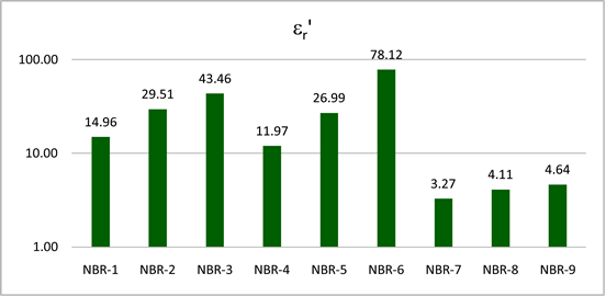
Figure 1. Real part of the relative dielectric permittivity of NBR-based vulcanizates.
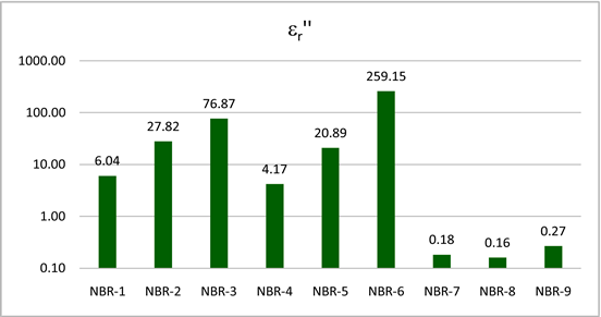
Figure 2. Imaginary part of the relative dielectric permittivity of NBR-based vulcanizates.
size which yield non-uniform interface phenomena. Hotta et al. [7] discussing the complex permittivity, claim it to be dependent on the specific surface area of the fillers. In our case CCB has specific surface area much higher than that of the nickel powder. The difference in particle size is also huge.
The magnitude of the dielectric loss angle is greatest with NBR-6 composite containing 60 phr carbon black as a filler, whereas at the concentration of 30 phr and 50 phr the values of and are higher in the triple systems, relative to those composites which contain as filler only carbon black or only nickel powder (Figure 3). These results are due to the fact that the dielectric losses in a multiple composite are the result of complex phenomena like natural resonance, dipole relaxation, electronic polarization as well as their relaxation and interfacial polarizations. Interfacial polarizations occur in heterogeneous media due to accumulation of charges at the interfaces and the formation of large dipoles [8] . The important factor is also the ratio between the particles of the fillers and the host materials [9] . The morphology and structure of the conductive filler, its size and shape, as well as the morphology and structure of the composite affect the changes in the real and imaginary part of the relative permittivity.
The electric conductivity (σАС) of the composites at 2.66 GHz is presented in Figure 4. As seen, composites NBR-2, NBR-3, NBR-5 and NBR-6 are highly electroconductive and NBR-6, possesses the highest σАС values. Composites conductivity is a function of a number of factors, but filler-filler and matrix-filler interactions are the determining ones [6] . The higher the filler loading in the matrix, the more the conductive paths in it are. Another factor is the so called “percolation threshold”―a certain concentration of the filler that causes a drastic conductivity increase. The number of conductive paths continues to increase at filler amounts higher than the percolation threshold. That leads to the formation of a complete conducting network, which can explain the high σАС value for NBR-6, as the percolation threshold for Printex is at about 25 phr. The results in Figure 4 allow the conclusion that the tertiary systems have σАС values higher than those of the composites loaded only with one filler at the same amount (30 phr and 50 phr). As Figure 4, shows σАС(NBR-1) > σАС(NBR-4) > σАС(NBR-7)

Figure 3. Tangent of dielectric loss angle of the composites studied.
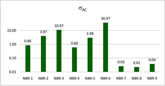
Figure 4. Electric conductivity of NBR-based vulcanizates.
and σAC(NBR-2) > σАС(NBR-4) > σАС(NBR-8). The order is due to the fact that CCB is able of forming a hybrid network with the Ni particles. The results in Figure 4 lead to the conclusion that composites NBR-7, NBR-8 and NBR-9 have very low conductivity, suggesting that the addition of only nickel powder does not cause the formation of conductive pathways at the filler concentrations studied.
Figures 5-7 plot the real ( ) and imaginary ( ) part of the relative magnetic permeability and the tangent of magnetic loss angle (tanδµ) of NBR-based vulcanizates at various concentrations of the conductive filler taken at 2.66 GHz.
The results reveal that the increasing filler concentration leads to significant changes in and for NBR-1, NBR-2, NBR-3 comprising a hybrid filler and for those with carbon black (NBR-4, NBR-5, NBR-6), while for those loaded with nickel powder the change is negligible. The magnetic losses for magnetic materials originate mainly from domain resonance, hysteresis loss, eddy current loss, and natural resonance. The domain wall resonance normally occurs at a frequency lower than 100 MHz, so it can be neglected in the microwave range.
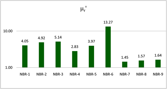
Figure 5. Real part of the relative magnetic permeability of NBR-based vulcanizates.
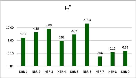
Figure 6. Imaginary part of the relative magnetic permeability of NBR-based vulcanizates.
Having measured relative permeability a low microwave power (≤5 mW), we claim that complex phenomena like eddy current loss and natural resonance are the main cause of the magnetic loss in the present study [10] , instead of hysteresis and domain resonance observed in the conventional case. Undoubtedly, the morphology and structure of the composites studied influence the mentioned phenomena.
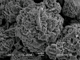
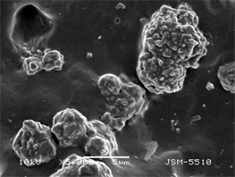
The explanations made are supported by the results obtained by scanning electron microscopy. Figure 8 shows different crystalline structures and formations of layered structure in the investigated nickel powder.
The aggregates of the nickel particles form crystalline structures of the “spiral rosette” type. The rosettes aggregate according to the forces of interaction between them and strive to have a pseudospheric shape. Spheres can also form tiles that make up twin-nano domains. The spiral growth of nano-twins forms the crystal “comb” structure (Figure 8(b)).
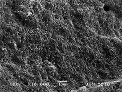
Figure 9 shows a SEM image of the used conductive carbon black Printex XE-2B.
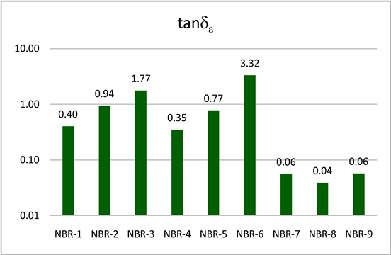
Figure 7. Tangent of magnetic loss angle of NBR-based vulcanizates.
 (a)
(a)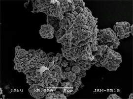 (b)
(b)
Figure 8. SEM images nickel powder at magnitude of 5000 (a) and 10,000 (b).
The picture shows the high structurality of the carbon black expressed via formation of chain aggregates, as well as the tendency of the latter to form agglomerates. Elementary particles are nano-sized.
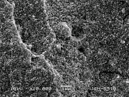
Figure 10 shows SEM images of the investigated vulcanizates filled at 30 phr.
It is clear from Figure 10(a) that nickel aggregates are made of crystalline “spiral-shaped” rosettes which retain their shape and dimensions upon being inserted into the elastomeric matrix. The individual aggregates are coated with a rubber film, forming agglomerates which are located in separate clusters in the matrix. That hinders the charge transfer and correlates with the high values of the specific volume resistivity.
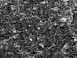
The image of the composite filled with conductive carbon black at 30 phr (Figure 10(b)), is quite different. The size of carbon particles is much smaller
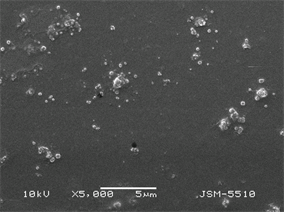
Figure 9. SEM image of Printex ХЕ-2В carbon black (cross section).
 (a)
(a) 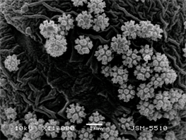 (b)
(b)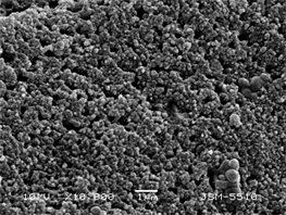 (c)
(c)
Figure 10. SEM images of NBR composites СЕМ filled with: (a) nickel power; (b) CCB; (c) nickel power + CCB at 30 phr.
than the size of the nickel ones what results in a significant increase in the number of charge carriers. The micrograph clearly shows the structures of the filler, and its particles being in direct contact with each other, what leads to their microscopic conductivity of an ohmic character. The elastomeric layers between the individual aggregates and agglomerates are very thin, and therefore are overcome easily by charge carriers in the tunnel transfers. That explains the low specific volume resistivity values for the composites containing CCB. The image of the composite filled with a combination of the two fillers at a total of 30 phr (Figure 10(c)), is identical to that of the composite filled with CCB at 30 phr. Here in some places we can see the aggregates and agglomerates of the nickel particles, which stand out in their larger dimensions, but the chain-like structures of CCB particles, which act as conducting paths, predominate in the elastomeric matrix. The similarity in the morphology of the two composites also explains their close values of specific volume resistivity, electrical conductivity, respectively.
Figure 11(a) shows clearly the nickel aggregates made up of a large number of particles of different size which are isolated from each other with a coating layer cutting the contact between them. In addition, the aggregates themselves are encapsulated by an elastomeric layer and are located in the matrix itself on separate islands remote from one another. That impedes greatly the charge transfer and blocks the high electrical conductivity of the nickel powder. In the composite, filled with CCB at 60 phr (Figure 11(b)), the location of the carbon black particles in the elastomeric matrix is identical to that of the composite filled with
 (a)
(a)
 (b)
(b)
 (c)
(c)
Figure 11. SEM images of NBR composites filled with: (a) nickel powder; (b) CCB; (c) nickel powder + CCB at 60 phr.
CCB at 30 phr, with the difference that there are larger clusters of carbon particles in the chain aggregates and the distance between the aggregates themselves is smaller. That facilitates the transport of electrons and ρv decreases, but to a lesser extent because the distance between the particles cannot be reduced to infinity and a dynamic equilibrium is established. The morphological structure of carbon black particles that make up the conductive paths and their phase controls the electrical conductivity of the vulcanizate predominates in the composite filled with nickel powder at 30 phr and with CCB at 30 phr (Figure 11(c)). Here too, the aggregates of nickel particles have no relation to the conductive paths. Due to the lower amount of CCB compared to the composite in Figure 11(b), the distance between the carbon particles and their aggregates is greater, resulting in a higher ρv value.
The comparing Figure 10(a) and Figure 11(a) one sees that, with increasing the concentration of nickel powder from 30 phr to 60 phr the nickel aggregates become larger and not so well defined.
The comparison of Figure 10(b) and Figure 11(b) reveals that, at a higher CCB concentration the clusters of carbon black particles in the chain aggregates enlarge and the distance between the aggregates is shorter, hence the electrical conductivity gets higher (Figure 4).
As Figure 10(c) and Figure 11(c) show, with increasing the filler concentration the aggregates become larger, but very different in shape and size.
The images obtained by SEM demonstrate clearly that the particles and aggregates are well dispersed in the elastomeric matrix in all composites filled with CCB unlike the nickel powder particles. However, in the presence of carbon black, the dispersion of nickel particles is better. The presented results from SEM studies on the composites confirm categorically that the differences observed in the values of their dielectric permittivity and magnetic permeability, and the tangents of the dielectric and magnetic losses angles are due to significant differences in morphology and structure of the very fillers and of composites filled with the latter. Obviously, the morphology and structure have a significant impact on the phenomena forming the dielectric permittivity and magnetic permeability values described above. It is also obvious that, the morphology and structure of the fillers used are very different. As seen, the particle size and occurrence of particles clustering, the arrangement of the particles in the matrix and the phenomena in the interface region between the matrix and the filler have a significant effect on the permittivity and permeability of the composite materials investigated.
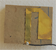
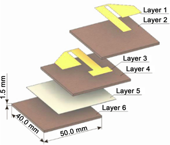
The different types of vulcanizates studied were built into a microwave dipole antenna with a reflector as substrates or insulating layers in flexible antenna for body centric communications (BCCs). The constructed model antenna had three metallic (Figure 12(a)―layers 1, 3 and 5) and three polymer layers (Figure 12(a), layers 2, 4 and 6), and can operate in the industrial, scientific, and medical (ISM) band in the range of 2.40 - 2.48 GHz.
 (a)
(a)
 (b)
(b)
 (c)
(c)
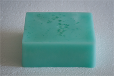
Figure 12. Structure of the antenna (a), photograph of the antenna (b) and photograph of the homogeneous flat phantom (c).
Composite NRK (formulation in phr: acrylonitrile butadiene rubber-100, zinc oxide-3, stearic acid-2, processing oil (Petronet 620N)-10, TMQ-1, TBBS-1.5, sulfur-2, kaolin-50) was used in layers 2, 4; composites from NBR-1 to NBR-9 (formulations in Table 1) were used in layer 6. The structure of the antenna as well as its dimensions are shown in Figure 12. The electromagnetic parameters of the NRK composite measured at 2.56 GHz are as follows: = 2.48, = 0.02, tanδe = 0.006, σАС = 0.0021.
The first series of studies we conducted aimed at showing the absorption of electromagnetic energy from each composite with a conductive filler, while the subsequent studies aim at demonstrating the applicability of the composites to reduce the specific absorption rate (SAR) which is a value that measures how much power is absorbed in a biological tissue when the body is exposed to electromagnetic radiation [11] . SAR is determined as follows:
(1)
where E is the electric field (V/m), σ is the conductivity (S/m), and ρ is the density (kg/m3) [12] .
The SAR was computed using FDTD numerical technique by placing a homogeneous human body model (Figure 12(c)) near the antenna. In the course of the study, numerical models of nine antennae were constructed, in each of which the last antenna layer (Layer 6 located behind the reflector) consisted of one of the composites from NBR-1 to NBR-9. Table 2 presents the materials from which the individual layers of the investigated antennae were made. Each antenna is placed directly on the surface of the flat phantom composites from NBR-1 to NBR-9. Each antenna is placed directly on the surface of the flat phantom to study how the insulating layer consisting of one of the composites with conductive fillers (NBR-1 to NBR-9) reduces SAR. Figure 13 shows results for the maximum mean 10 g average SAR in each of the composites with conductive fillers (NBR-1 to NBR-9). The 12-field components approach was used to calculate SAR in the voxel using xFDTD (xFDTD, Remcom Inc., State College, PA, USA) simulation software, based on the finite-difference time domain method
Table 2. Materials used to build the layers of the antennae studies.
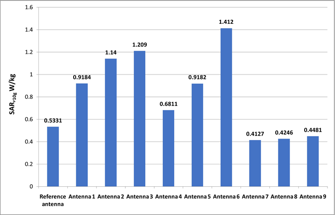
Figure 13. Maximum averaged 10 g SAR values caused by investigated antennaе in composite layers and flat phantom.
(FDTD). All results were normalized to a net input power level of 100 mW. As seen, the lowest electromagnetic was power absorbed by the sixth layer of the antenna when it is made of composite NBR-7. This effect can be related to several factors, namely to the lower dielectric permittivity of the composite, lower dielectric losses, and lower conductivity regarding the composites with a conductive filler.
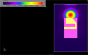
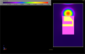
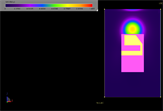
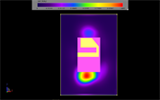
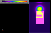
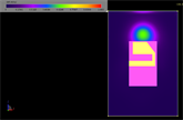
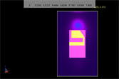
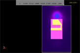
Figure 14 shows results for the distribution of SAR over the flat phantom surface caused by an antenna whose last layer is made of one of the composites with the conductive filler (NBR-1 to NBR-9).
According to the above figure, the highest SAR values of the surface of the phantom are observed when the last layer of the antenna is made of composites NBR-2, NBR-3 and NBR-6. These results can be related to the conductivity of the three composites which are higher than that of the rest (Figure 4). High conductivity leads to a current flow both on the surface of the reflector and on the surface of the last composite layer, which in turn leads to the generation of surface waves on the surface of the flat phantom and hence to higher SAR values. It should be noted that, the highest SAR value induced at an input power of 100 mW is lower than the maximum one set in international standards and recommendations [13] [14] . On the other hand, the generation of surface waves can be used when the two antennas (transmitting and receiving) are located on the surface of the human body, for example in cases of on-body communications in Body area networks. Analyzing the results in Figure 14, one also sees that antennae with NBR-7, NBR-8 and NBR-9 composites in the third layer of the antenna cause the lowest SAR values of the flat phantom surface. This result may be associated with several factors, namely, the lower dielectric permittivity of the
 (a)
(a)
 (b)
(b)
 (c)
(c)
 (d)
(d)
 (e)
(e)
 (f)
(f)
 (g)
(g)
 (h)
(h)
 (i)
(i)
Figure 14. SAR distribution over the flat phantom and antenna when Layer 6 is made of composites NBR-1 to NBR-9.
composite and the lower conductivity of the composite comprising a conductive filler. The lower conductivity of composites NBR-7, NBR-8 and NBR-9 does not allow the electric current to flow from the surface of the reflector to the surface of the flat phantom, therefore the electromagnetic field on the surface of the phantom is weaker, and hence SAR values are lower.
As a result of the research we can conclude that the studied composites can find application as insulating layers and substrates in flexible antennas, depending on the antenna application. For example, composites of higher conductivity can be used in applications where surface waves are generated to realize on-body communications, whereas composites with lower conductivity can be used for antennas that will be on the body of a person and will transmit to and receive from other antennas that are not on the same person's body (off-body communications). It is clear that we can engineer the properties of an antenna substrate at microwave frequencies by adjusting the content and type of the filler and thus control the antenna performance. It will allow us to tailor an antenna performance specific to a particular application.
4. Conclusions
The complex permittivity and permeability of composites containing conductive fillers―very different in their type and chemical nature―conductive carbon black, nickel powder, and combinations thereof―were investigated. The properties of the dual and tertiary composites were evaluated at the same degree of filling. A noticeable influence of the morphology and structure of both fillers and the composites on their permittivity and permeability values was established. It can be argued that particle size and occurrence of particle clustering; arrangement of the particles in the matrix and phenomena in the interface region between the matrix and the filler are the crucial factors for the permittivity and permeability formation of the composite materials investigated.
The investigations covered the possibilities to use the composites in antennae making, in particular as substrates and insulating properties in body centric communications (BCCs) flexible antennas. The research allows the conclusion that the studied composites can be used for such purposes depending on the application of the antenna. Higher conductivity composites can be used in applications where surface waves are generated to provide on-body communications, while lower conductivity composites may be used for antennas that will be on the body of a person and will transmit to and receive from other antennas that are not on the body of the same person (off-body communications). It is clear that one can engineer the antenna substrate properties at microwave frequencies by adjusting the content and type of filler and thus control and tailor the antenna performances specific to particular applications.
Acknowledgements
King Khalid University, Saudi Arabia gave very valuable support for this research through a grant # RCAMS/KKU/006-18 under the Research Center for Advanced Materials Science and the authors would like to acknowledge this support and that of the University of Chemical Technology and Metallurgy, Sofia, Bulgaria.
Conflicts of Interest
The authors declare no conflicts of interest regarding the publication of this paper.
Cite this paper
Al-Sehemi, A.G., Al-Ghamdi, A.A., Dishovsky, N.T., Atanasov, N.T. and Atanasova, G.L. (2018) Complex Permittivity and Permeability Studies Viewing Antenna Applications of NBR-Based Composites Comprising Conductive Fillers. Materials Sciences and Applications, 9, 883-899. https://doi.org/10.4236/msa.2018.911064
References
- 1. Oohira, K. (2008) Development of an Antenna Materials Based on Rubber that Has Flexibility and High Impact Resistance. NTN Technical Review, 76, 58-63.
- 2. Raees, M., Dar, S.H. and Ahmed, J. (2016) Characterization of Flexible Wearable Antenna Based on Rubber Substrate. International Journal of Advanced Computer Science and Applications (IJACSA), 7, 190-195.
- 3. Balanis, C.A. (2005) Antenna Theory: Analysis and Design. 3rd Edition, John Wiley & Sons, Hoboken.
- 4. Baker-Jarvis, J., Janezic, M.D. and Degroot, D.C. (2010) High Frequency Dielectric Measurements. IEEE Instrumentation & Measurement Magazine, 13, 24-31. https://doi.org/10.1109/MIM.2010.5438334
- 5. Gupta, B., Sankaralingam, S. and Dhar, S. (2010) Development of Wearable and Implantable Antennas in the Last Decade: A Review. Proceedings of the 10th Mediterranean Microwave Symposium, Turkey, 25-27 August 2010, 251-267.
- 6. Al-Ghamdi, A.A., Al-Hartomy, O.A., Al-Solamy, F.R., Dishovsky, N.T., Malinova, P., Atanasov, N.T. and Atanasova, G.L. (2016) Conductive Carbon Black/Magnetite Hybrid Fillers in Microwave Absorbing Composites Based on Natural Rubber. Composites Part B: Engineering, 96, 231-241. https://doi.org/10.1016/j.compositesb.2016.04.039
- 7. Hotta, M., Hayashi, M., Lanagan, M.T, Agrawal, D.K. and Nagata, K. (2011) Complex Permittivity of Graphite, Carbon Black and Coal Powder in the Ranges of X-Band Frequencies (8.2 to 12.4 GHz) and between 1 and 10 GHz. ISIJ International, 51, 1766-1772. https://doi.org/10.2355/isijinternational.51.1766
- 8. Mirsha, M., Singh, A.P., Sambyal, P., Teotia, S. and Dhawan, S.K. (2014) Facile synthesis of Phenolic Resin Sheet Consisting Expanded Graphite/-Fe2O3/SiO2 Composite and Its Enhanced Electromagnetic Interference Shielding Properties. Indian Journal of Pure and Applied Physics, 52, 478-485.
- 9. Thomas, S., Chan, C.H., Pothen, L.A., Joy, J. and Maria, H.J. (2013) Natural Rubber Materials: Volume 2: Composites and Nanocomposites. Royal Society of Chemistry, Cambridge.
- 10. Song, N-N., Yang, H.-T., Liu, H.-L., Ren, X., Ding, H.-F., Zhang, X.-Q. and Cheng, Z.-H. (2013) Exceeding Natural Resonance Frequency Limit of Monodisperse Fe3O4 Nanoparticles via Superparamagnetic Relaxation. Scientific Reports, 3, 3161.
- 11. Fujimoto, K. and James, J.R. (2008) Mobile Antenna Systems Handbook. 3rd Edition, Artech House Inc., Norwood.
- 12. Raad, H., Abbosh, A., Al-Rizzo, H. and Rucker, D. (2013) Flexible and Compact AMC Based Antenna for Telemedicine Applications. IEEE Transactions on Antennas and Propagation, 61, 524-531. https://doi.org/10.1109/TAP.2012.2223449
- 13. ICNIRP (1998) Guidelines for Limiting Exposure to Time-Varying Electric, Magnetic, and Electromagnetic Fields (up to 300 GHz). Health Physics, 74, 494-522.
- 14. (2006) IEEE Standard for Safety Levels with Respect to Human Exposure to Radio Frequency Electromagnetic Fields, 3 kHz to 300 GHz, IEEE Std. C95.1-2005.