Materials Sciences and Applications
Vol.5 No.9(2014), Article
ID:48449,11
pages
DOI:10.4236/msa.2014.59069
Failure Analysis of an Aluminum Extension Portable Ladder
Abdel-Hakim Bouzid
Department of Mechanical Engineering, École de Technologie Supérieure, Montreal, Cananda
Email: hakim.bouzid@etsmtl.ca
Copyright © 2014 by author and Scientific Research Publishing Inc.
This work is licensed under the Creative Commons Attribution International License (CC BY).
http://creativecommons.org/licenses/by/4.0/


Received 20 May 2014; revised 22 June 2014; accepted 5 July 2014
ABSTRACT
The conditions of end supports of straight ladders are often the cause of major injuries. The firm and secure ladder ends against instability in general and sliding of the top and bottom ends in particular are among the check list of most ladder safety training books and manuals. However, the restraint to the free expansion of a ladder can cause a catastrophic failure due to buckling even at intermediate loads and should be presented in the latter as a serious potential hazard. This paper deals with an investigation of an extension. An analytical structural model that simulates the buckling behavior of an axially restrained ladder subjected to static and dynamic loading is developed. It compares two different ladder end conditions and shows that instability due to buckling can occur during ascension or descent in the case of an axially restrained ladder. The analytical results are supported and validated by a finite element model simulation conducted in parallel. This study may explain the root cause of similar incidents involving falls from portable ladders worldwide.
Keywords:Portable Ladder, Beam Shortening, Columns Axially Restrained, Buckling

1. Introduction
Reports on ladder safety have shown some startling statistics related to ladder accidents worldwide. Every year millions of people are injured and thousands are killed. In the US the Consumer Product Safety Commission reported more than 90,000 people receive emergency room treatment from ladder-related injuries every year and over 300 people die from ladder falls annually. According to the Canada’s occupational safety and health magazine, statistics on lost-time injuries list approximately 1500 accidents in Canada involving ladders with over 40 deaths per year. Based on a study conducted on the 24,882 ladder falls of 1987, OSHA estimates that 53% of the ladders are involved in the accidents broke during use. The main cause of ladder failure is the sliding of the bottom and the top ladder ends [1] -[3] and the buckling of the beam side rails [4] . While the former cause is rather simple to verify the second cause is often stated in the incident reports without giving the origin and intensity of the loads developed to cause such a buckling failure. The quality control of the aluminum material and the extrusion process used to produce the beam side rails and rungs are often to blame.
The investigation of the cause of a fall is often followed by a thorough inspection of the incident seen and an examination of the used ladder but seldom simulation whether analytical, numerical and experimental are undertaken. This is because the assumptions, simplification and conditions for the simulations to reproduce the incident are difficult to make. Kenner et al. [5] examined such factors in the analysis of step ladder damaged in the field and concluded that these structures were more complex than they might appear. In fact, in an investigation on the root cause analysis [6] they showed that the ladder was damaged as the result of the user impact of the ladder after substantially tipping over.
When ladders fail, it is important to gather information about operating conditions and to obtain a professional engineering assessment of the cause. This is one of the recommendations that were given in the report on the incident of a New York City fire fighter rescue attempt that caused a collapse of an aerial ladder [7] . The ladder support conditions can have a major impact on the stability and integrity of columns. Imperfections such that initial straightness or curvature, the friction and rigidity of the end supports and the effective length are just to name a few. Several studies have been conducted on axially restrained columns under high temperature [8] -[10] . When subjected to fire, the imposed axial restraint against column thermal expansion causes additional axial forces to be generated and develops excessive buckling deformations. The effect of one column end rigidity on the stability of a column subjected to an intermediate concentrated load was treated in [11] . However, in these treated cases a modified Euler approach is used because there is no lateral load involved. Nonetheless the authors caution against the use of such a simplified approach.
This study deals with axially restrained columns. A model based on beam-column is used to treat an aluminum extension portable ladder and to explain its buckling failure. The study shows that the axially restrained side beams can create instability at even intermediate loads. The restraint to the free expansion of ladders and their end support conditions are not treated by standards such as CSA and ANSI [12] [13] .
2. Analytical Modeling
Ladders are design against buckling due to compression. The normal buckling load limit is determined on the basis of the weight of the worker, the carried load and his tools. The ladder load capacity limit is obviously greater to allow for a margin of safety. However portable ladders are not designed to carry certain loads such as pure lateral loads or load generated during operation by supports and attachments other than those mentioned previously. If the free expansion of a ladder is limited as shown in Figure 1, then considerable compression load may be generated which coupled to a dynamic lateral load due to a moving worker can cause a serious buckling problem. This case of combined compressive axial load and bending is known as beam-column. Figure 2 shows a free body diagram of the portable ladder with two different top supports 1) a roof and 2) a wall for comparison. The detail study of the case of a ladder with a roof support will follow.
2.1. Beam Shortening
First, Beam shortening is a reduction of the length of a structural beam when subjected to loading. It can be produced by an axial compressive force or thermal contraction but also by bending. With reference to Figure 1, the shortening δc due to compression in the two parts of the ladder Pb for the length b and Ph for the length (L-b) is given by:
 (1)
(1)
when a beam is subjected to bending, its length decreases, that is to say, its neutral axis becomes shorter due to curvature [14] . This phenomenon is neglected in beam theory governed by small deformation. However, the shortening of a beam subjected to bending is a real phenomenon that generates an important axial compressive load if the beam is restrained from expansion when bending is released, which is the case of the ladder. The beam shortening δf as a result of bending is given in [15] such that:
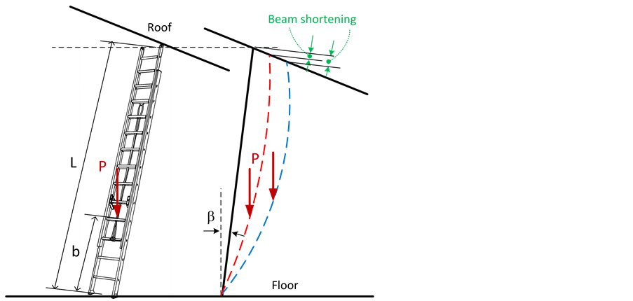
Figure 1. Beam shortening effect in portable ladder.
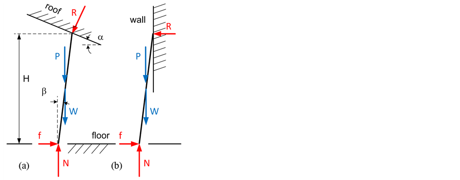
Figure 2. FBD of the portable ladder with (a) roof support (b) wall support.
 (2)
(2)
The relationship between the moment M and the deflection v is well established (Timoshenko et al. 1961). Singularity functions are used to determine the moment:
 (3)
(3)
After substitution, integration and application of the boundary conditions, the beam shortening of a simply supported inclined ladder is given by
 (4)
(4)
The total beam shortening is therefore given by:
 (5)
(5)
During unloading, if the beam ends are constrained this will generate an important axial compression. In this case, the ladder end is blocked against the rigid inclined roof and depending on the stiffness coefficient of the combined end pads and the roof contact system ka, the magnitude of the generated compressive force Equation (6) can cause buckling of the ladder. The stiffness coefficient can have any value between 0 and 1; 0 means that the compressive load is completely absorbed and 1 the complete beam shortening is transformed to a maximum compressive load. The compressive force is given by:
 (6)
(6)
2.2. Buckling of a Beam-Column
The template is used to format your paper and style the text. All margins, column widths, line spaces, and text fonts are prescribed; please do not alter them. You may note peculiarities. For example, the head margin in this template measures proportionately more than is customary. This measurement and others are deliberate, using specifications that anticipate your paper as one part of the entire journals, and not as an independent document. Please do not revise any of the current designations.
The ladder is treated as a beam-column because it is subjected to the simultaneous action of axial compression and flexion in this particular case. Lateral loads creates an instability because the moment is amplified considerably even in cases of small deflection. The two loads cannot be treated separately and the theory of the buckling of beam-columns must be used [16] . The equations of lateral displacement and the amplified moment of a beam-column simply supported and subjected to a lateral load defined by the normal component of a worker weight P sinβ applied on the inclined ladder at a distance b from the floor is given by:
 (7)
(7)
 (8)
(8)
The allowable axial compressive and bending load limits of a beam-column is given by a linear combination of the maximum bending and compressive loads expressed by the following relationship adopted by most standards:
 (9)
(9)
Cr, Mrz et Mry are the maximum compressive load and bending moments when taken individually with all other loads set to zero. Mz and My are the amplified moments in the two directions obtained by Equation (7). In the ladder case, only the bending in the plane normal to the steps is considered and therefore My = 0. A similar equation is suggested by CSA 157-05 standard [17] and will be used for comparison.
3. Numerical FE Analysis
The analytical beam shortening study is supported and validated by a numerical finite element buckling study that was run in parallel. The FE model shown in Figure 3 represents the portable ladder of Figure 1 with its three sections; the top section composed by 7 rungs the bottom section composed of 7 rungs and the overlap section composed of two rows of 5 rungs each. Three-node beam elements are used to model the beam side rails and the rungs. The bottom ends of the beam side rails are fixed in displacement in the three directions. A former experimental study on the friction condition of the rubber pad shoes with the floor showed that the coefficient of friction is greater than 0.3 while only 0.123 is sufficient to avoid the slippery conditions for the present situation. The top end nodes of the beam side rail can only move in the direction of the beam length when the load is applied in order to evaluate the amount of beam shortening as the worker climbs the ladder. Its weight is amplified
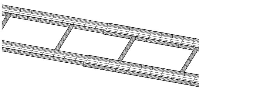
Figure 3. Partial view of the portable ladder FE model.
depending on ascension or descent. The amplification factors are taken as 1.5 and 2 in a first case and 1.75 and 2.5 in a second case respectively in order to cover a possible range. The weight of the ladder is also considered in the numerical analysis.
To simulate the additional compressive load generated by the difference between the dynamic and static loading due to the ladder expansion constraint, a second run is conducted imposing the amount of an axial displacement obtained from the non-linear analysis of a first run with the ladder simply supported. This generates the resulting compressive force which obviously depends on the worker position on the ladder. A third run combining axial compression and bending with the buckling option is finally conducted to evaluate the capacity of the ladder to resist buckling. The analysis was run under Ansys software [18] the non-linear option to account for large deformation and in particular the change in the ladder length when subjected to bending. A mesh convergence criterion was applied based on buckling. It consisted of refining the refined until the change in the buckling load was less than 1%.
4. Case Study
According to the information gathered by the CSST “Commission de la Santé et Sécurité du Travail” which is the Quebec occupational health and safety organization, a worker of about 100 kg died from a fall from a ladder deployed at a height of rung 19 or 5.8 m with a 10˚ relative to the vertical. The lower supports with durable shoes rested on a terrazzo floor while the upper end caps were in contact with a rigid ceiling inclined at 29˚ with respect to the horizontal, as shown in Figure 1. It is important at this point to pay attention to the particular use of the ladder because normally its upper ends are supported on a vertical wall, or both side rails are supported on the edge of the wall if the latter is shorter. The 24 feet long or 7.3 m and 6.8 kg weight ladder of category 3 was deployed at a height of 19 feet or 5.8 m and there was an overlap of five rungs (1.5 m). The worker climbed to the 13th rung to change fluorescent tubes. A second worker held the ladder secure to the ground and prevented it from sliding. The accident occurred just after the second worker released the ladder to get spare fluorescent tubes while the worker on the ladder prepared his descent to be able to grab the tubes. The complete detailed study on the root cause included the bottom slip and the loss of contact at the ceiling due to curvature produced by normal bending and the buckling under the combined flexion and compression. The investigation showed that the collapse of the ladder shown in Figure 4 is due to buckling failure. The unexpected high loads were generated as a result of the side rail beam free expansion restraint due to the end supports.
5. Results and Discussion
5.1. Lower End Sliding Condition
The first intervention was to eliminate the possibility of ladder bottom end sliding failure. This was achieved by conducting a friction test experiment at the accident seen. Figure 5 shows a picture of the ladder shoe with the position of the load reaction location. Because the shoe was warn-out, it was decided to apply the load on the shoe at the different position shown in Figure 3 to cover the range of possible contact with the floor. Figure 6 shows the coefficient of friction obtained for both ladder shoes. Several tests were conducted, however the graph
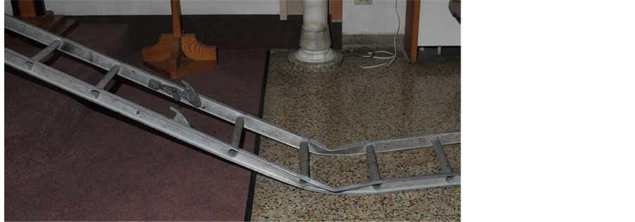
Figure 4. Portable ladder buckling.
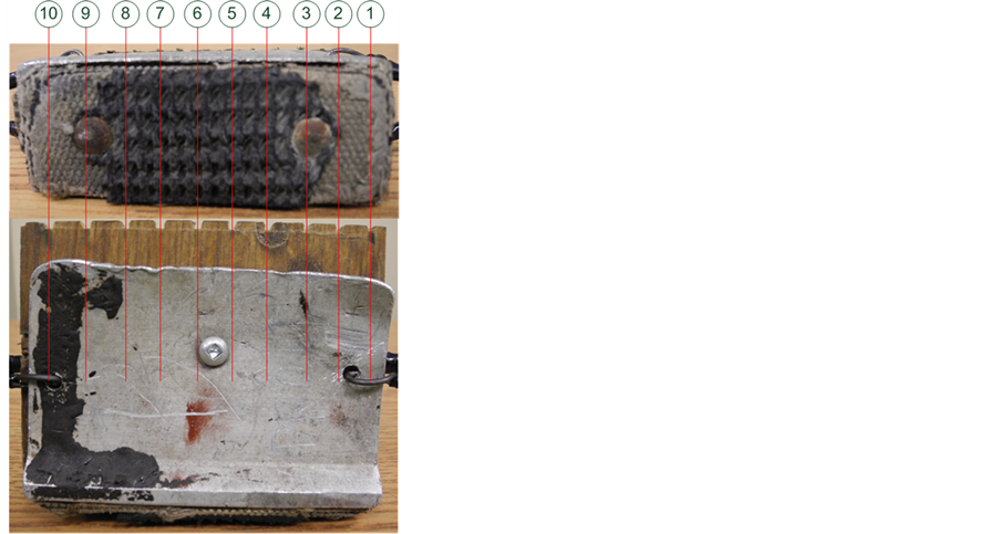
Figure 5. Load application location on the ladder shoe for friction tests.
shows only the maximum and minimum friction coefficient values indicating that the tests are repeatable. Depending on the shoe and the load position, the friction coefficient varies between 0.3 and 0.6. The higher values are indicative of the rubber being the predominant material contact surface
Figure 7 gives the minimum required coefficient of friction as a function of the ladder angle with the vertical to avoid sliding. A comparison with the ladder top end resting against a vertical wall and the current case of contact with an inclined rigid roof is given. For the small angles, the required friction force necessary to avoid sliding is the same in both cases. It is clear that for an 8 degrees angle sufficient friction exists between the ladder bottom shoes and the floor exist to avoid sliding since the minimum required coefficient of friction is 0.123. However since black rubber marks were found on the floor, it can only be concluded that the friction coefficient is high and that sliding had occurred at some point. This was only possible if the contact at the top end was lost due to a considerable amount of axial deformation to clear the roof which pointed to the fact that buckling failure was the probable cause.
5.2. Effect of Dynamic Factors
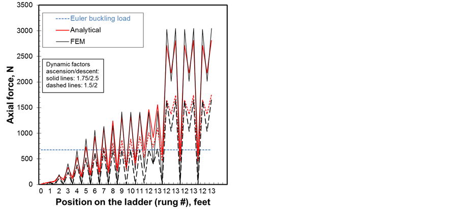
Figure 8 and Figure 9 show the variation of the axial displacement and force, bending moment and the buckling parameter for one ladder beam as a function of worker position on the ladder. These four parameters depend on
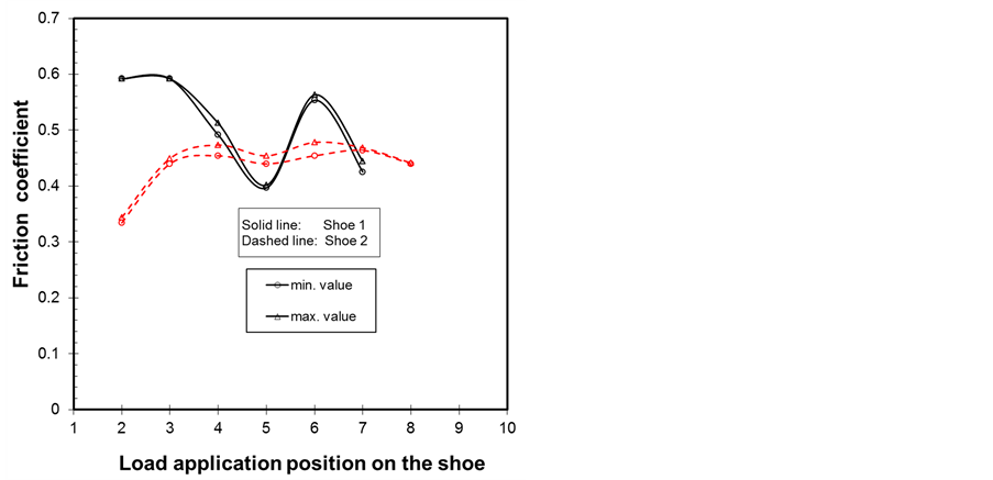
Figure 6. Friction coefficient test results.
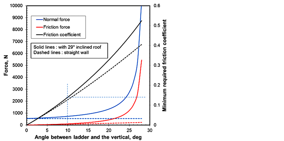
Figure 7. Friction coefficient requirement to avoid sliding.
dynamic factors due to the ascension/descent and the load absorption coefficient due to the end pads and the roof flexibility. In general it could be said that the results of the analytical model are in a good agreement with those of FEM and in particular the axial compressive displacement or beam shortening and the axial compressive force shown.
The effect of the dynamic factors is illustrated for ratios of 2.5 to 1.75 and 2 to 1.5 are used in the simulation [19] . As the worker climbs the ladder towards the rung 13, these four parameters increase. It is to be noted that for each rung climbed, there are two states; the first one presents the dynamic state in which the worker is in movement causing a pulse load and the second one is the static case in which the worker stops instantaneously any movement of ascension or descent. The values are greater for dynamic states. When the worker reaches rung 9, i.e., the middle of the ladder, the maximum values are reached. Passed this step some parameters start to level off or slightly decrease before increasing drastically on the descent. In fact, once the descent is initiated from rung 13 down to rung 12, the bending moment of the ladder is higher because the dynamic factor is higher at descent. Adding to the fact that the axial compressive force is higher during this movement, this causes the
 (a)
(a)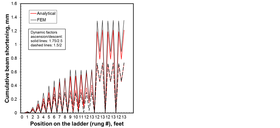 (b)
(b)
Figure 8. Dynamic factors effect on (a) axial displacement and (b) axial force.
 (a)
(a)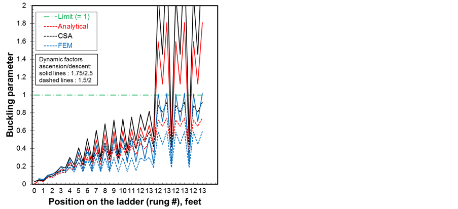 (b)
(b)
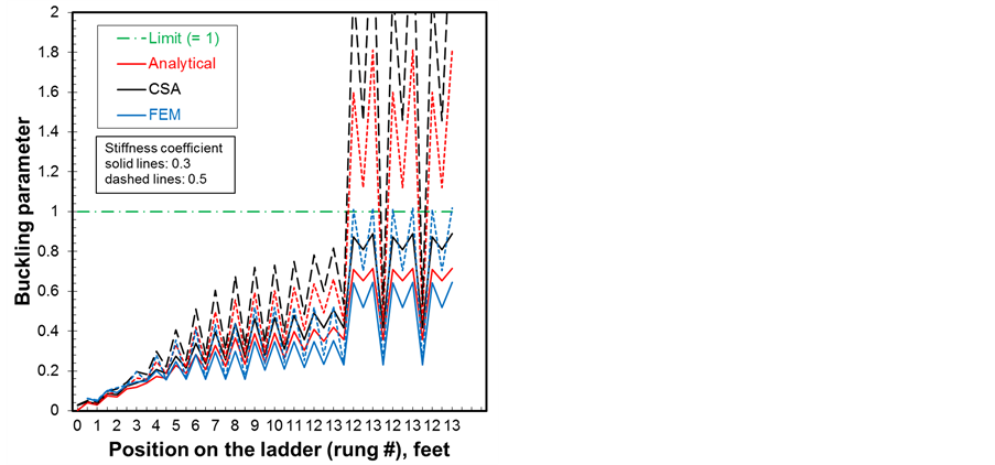
Figure 9. Dynamic factors effect on (a) bending and (b) buckling.
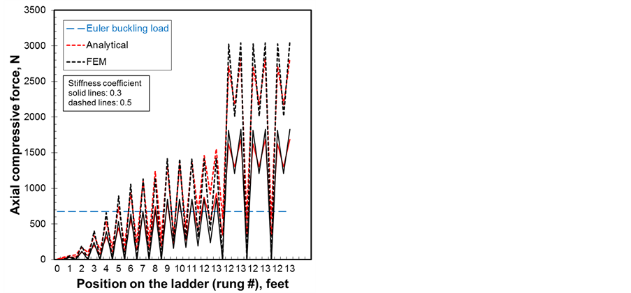
bending moment and lateral displacements to amplify causing instability. It is to be noted the Euler buckling load for a column is given only for a reference in the axial force vs. position on the ladder graph of Figure 8(b). It should not be considered as a load limit criteria for buckling because the ladder behaves as a beam-column and therefore the buckling parameter defined by Equation (9) and shown in Figure 9(b) obtained for the different method should be considered. The CSA standard method gives the higher buckling parameter with all method showing buckling to occur with the most probable case with dynamic factors of 1.75/2.5. If the CSA method is considered rather conservative the analytical and FE models do not account for material defect, initial deflection or curvature, eccentricity and other factors that are taken care of somewhat by the CSA method. For the effect of dynamic factors, these calculations are conducted with a stiffness coefficient of 0.5.
5.3. Effect of Stiffness Coefficient
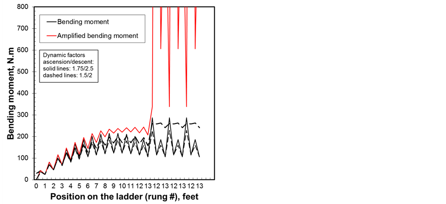
Figure 10 and Figure 11 show the effect of the stiffness coefficient on the four previously stated parameters. Values of 0.5 and 0.3 representing compression load absorption of 50% and 70% respectively are considered.
 (a)
(a) (b)
(b)
Figure 10. Stiffness coefficient effect (a) axial displacement and (b) axial force.
 (a)
(a)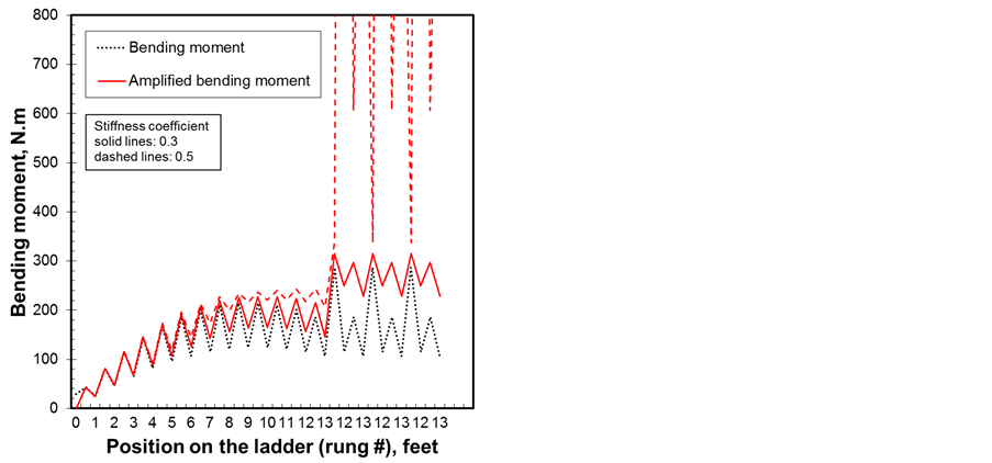 (b)
(b)
Figure 11. Stiffness coefficient effect on (a) bending and (b) buckling.
The calculations are done with the dynamic factors of 1.75/2.5. The higher the stiffness coefficient is the less compression load is absorbed and therefore the higher the four parameters are. Once again, as the worker climbs the ladder towards rung 13 the loads increase and the risk of instability is higher and in particular with the 0.5 value. The bending moment and its amplified values due to the effect of compression are shown in Figure 11(a). It is clear that when the worker engages in the descent from rung 13, lateral deflections and bending are amplified causing instability and in particular when little or no absorption of the load occurs. This study is consistent with the second worker declaration that the accident occurred just after he released the ladder to get spare fluorescent tubes while the worker on the ladder prepared his descent to be able to grab the tubes.
6. Conclusions
The ladder collapse due to buckling is confirmed as the probable cause of failure by both the developed analytical model and the CSA 157-05 which is more conservative. The reduction of the dynamic factors from 1.75 and 2.5 to 1.5 and 2 leads to a reduction in the compressive load but are not enough to prevent the amplification of the deflection and bending. The instability occurred when the worker made his descent from the 13th to the 12th foot step to prepare for reception of the spare fluorescent tubes. Indeed, as soon as the worker began the descent to land on the 12th rung from the 13th rung, the collapse of the ladder was inevitable due to dynamic loading. The flexibility of the parts in contact with the legs (shoes, caps, floor and ceiling) can partially absorb the load created by the beam shortening but cannot prevent the collapse because even with a stiffness coefficient of 0.3 (70% of load absorption) buckling is reached.
Beams and columns axially restrained to free expansion such as the ladder under investigation experience high axial loads that make them buckle. Bending creates beam shortening that can produce buckling failure if axial displacement is restrained and the load is released. Six recommendations have been made: 1) do not use this type ladder of ladder for ceiling jobs; 2) ladders should not be axially restrained to free expansion; 3) use ends with rollers if the top end rests against an inclined wall; 4) caution against the use of a ladder with end restraint; 5) caution against this danger in the safety instructions, operating manuals and maintenance of ladders; and 6) analyze similar incidents involving temperature expansion restriction (i.e., collapse of firefighter areal ladders).
Acknowledgements
The author acknowledges the financial support of the Quebec provincial health and occupational safety “Commission de la Santé et de la Sécurité du Travail CSST”. He also would like to thank this organization for authorizing the publication of this investigation.
References
- Dewar, M.E. (1977) Body Movements in Climbing a Ladder. Ergonomics, 20, 67-86. http://dx.doi.org/10.1080/00140137708931602
- Hakkinen, K.K., Pesonen, J.P. and Rajamaki, E. (1988) Experiments on Safety in the Use of Portable Ladders. Journal of Occupational Accidents, 10, 1-9. http://dx.doi.org/10.1016/0376-6349(88)90002-8
- Chang, W.R., Chang, C.C., Matz, S. and Son, D.H. (2004) Friction Requirements for Different Climbing Conditions in Straight Ladder Ascending. Safety Science, 42, 791-805. http://dx.doi.org/10.1016/j.ssci.2004.02.002
- Snyder, G.A., Glancey J.L., Vinson J.R. and Cintavey, D.M. (2003) Failure Analysis of Step Ladders Manufactured from Extruded Aluminum. Proceedings of ASME 2003 International Mechanical Engineering Congress and Exposition, Washington, DC, 15-21 November 2003, 415-423.
- Kenner, M.T., Stevenson, M.E., Knox, E.H., Van Bree, M.P. and Wilkinson, J.A. (2011) Step Ladder Failure Analysis: A Comparison of Analytical Methods. Proceedings of ASME 2011 International Mechanical Engineering Congress and Exposition, 11-17 November 2011, Denver, 397-405.
- Knox, E.H., Van Bree, M.P., Kenner, M.T. and Wilkinson, J.A. (2009) Structural Stepladder Failure: Analysis of Root Cause. Proceedings of the ASME International Mechanical Engineering Congress and Exposition, 13-19 November 2009, Lake Buena Vista, 433-441.
- Routley, J.G. and Bush, R. (1996) Aerial Ladder Collapse Incidents. U.S. Fire Administration. Technical Report Series, USFA-TR-081, April 1996.
- Ali, F.A. and O’Connor, D.J. (1996) Calculation of Axial Forces Generated in Restrained Pin Ended Steel Columns Subjected to High Temperatures. Journal of Applied Fire Science, 6, 383-394. http://dx.doi.org/10.2190/J1GX-JA8P-HXYM-HN12
- Hozjan, T., Planinc, I., Saje, M. and Srpcic, S. (2011) Buckling of an Axially Restrained Steel Column under Fire Loading. International Journal of Structural Stability and Dynamics, 11, 451-472. http://dx.doi.org/10.1142/S0219455411004245
- Shepherd, P.G. and Burgess I.W. (2011) On the Buckling of Axially Restrained Steel Columns in Fire. Engineering Structures, 33, 2832-2838. http://dx.doi.org/10.1016/j.engstruct.2011.06.007
- Subramanian, R. and Venkateswara, R.G. (1987) Stability of Columns Subjected to an Intermediate Concentrated Load with One End Elastically Restrained to Move Axially. Computers and Structures, 25, 105-107. http://dx.doi.org/10.1016/0045-7949(87)90221-5
- CSA-Z11-FM81 (2011) Portable Ladders. CSA Standards.
- ANSI ASC A14.2 (2007) Ladders—Portable Metal—Safety Requirements.
- Kurrer, K.E. (2008) The History of the Theory of Structures—From Arch Analysis to Computational Mechanics. Ernst &Sohn, Berlin.
- Young, W.C. and Budynas, R.G. (2001) Roark’s Formulas for Stress and Strain. 7th Edition, Mc-Grew-Hill, New York.
- Timoshenko, S.P. and Gere, J.M. (1961) Theory of Elastic Stability, 2nd Edition, McGraw-Hill, New York.
- CAN/CSA-S157-05/S157.1-05 (2010) Strength Design in Aluminum / Commentary on CSA S157-05—Strength Design in Aluminum. CSA Standard.
- ANSYS (2013) ANSYS Standard Manual Version 13.0.
- Glancey, J.L., Snyder, G.A., Vinson, J.R., Krisher, J. and Franklin, P. (2005) Fiberglass and Aluminum Step Ladder Performance under Dynamic loading Conditions. Proceedings of 2005 ASAE Annual International Meeting, 17-20 July 2005, Tempa, Paper Number: 055009.
Nomenclature
dc beam shortening due to a compression, mm;
df beam shortening due to a compressive force, mm;
dt total beam shortening due to a compressive force, mm;
a angle between the ceiling or wall and the horizontal, rad;
b angle between the ladder and the vertical, rad;
m minimum friction coefficient;
A aluminium channel section, mm2;
b distance between ground and worker, mm;
Cr maximum compressive force, N;
E aluminium Young’s modulus, MPa;
f friction force on one pad, N;
H ceiling height, mm;
I channel second moment of inertia, mm4;
ka absorption coefficient;
L deployed ladder length, mm;
M bending moment, Nmm;
My bending moment about y axis, Nmm;
Mz bending moment about z axis, Nmm;
Mry maximum bending about y axis, Nmm;
Mrz maximum bending about z axis, Nmm;
n (P/EI)1/2;
N floor reaction, N;
P vertical force acting on column, N;
Pc total compressive load acting on side beam, N;
Pb compressive force in the lower part of side beam, N;
Ph compressive force in the upper part of side beam, N;
R celling or wall reaction, N;
v deflection due to bending, mm;
Vb shear force in the ladder’s lower part, N;
Vh shear force in the ladder’s upper part, N;
x distance from the floor, mm;
x,y,z axial coordinates.