Materials Sciences and Applications
Vol.4 No.12(2013), Article ID:40532,7 pages DOI:10.4236/msa.2013.412098
3D Braided Material Based on Space Group R3 Symmetry
![]()
School of Mechatronics Engineering, Henan University of Science and Technology, Luoyang, China.
Email: mawensuo@126.com, yin-dong-dong@163.com
Copyright © 2013 Wensuo Ma, Dongdong Yin. This is an open access article distributed under the Creative Commons Attribution License, which permits unrestricted use, distribution, and reproduction in any medium, provided the original work is properly cited.
Received August 31, 2013; revised October 2, 2013; accepted October 27, 2013
Keywords: Point Group C3; Space Group R3; 3D Braided Geometrical Structure
ABSTRACT
A unit cell geometrical structure was found with the use of symmetry operations corresponding to the point group C3. Based on the symmetry of space group R3, a 3D braided geometrical structure was obtained by transforming the unit-cell. The features corresponding to this braided structure were studied. The fiber volume percentage and variational tendencies of the material were predicted by establishing a geometric model.
1. Introduction
3D braided composites with the excellent mechanical properties are widely used in the aerospace, defense and medical industries [1]. At present, most of the researches have focused on the four-step and two-step braiding methods.
Four-step braiding method was invented by Florentin invention in 1982, and the two-step braiding method was first invented by Poper and McConnell in 1987 [2]. The four-step three-dimensional braiding method has successfully been used in braiding the rocket nozzle and satellite enhanced phase with the structure of the support pieces. Mesoscopic structure and mechanical properties of the four-step 3D braided composites have been researched a lot [3-9]. Based on the four-step multi-dimensional braiding method, it has been applied to industrial processes successfully [5-9]. The three-dimensional multi-directional braiding process increased axial yarn in braided direction or the other two directions which are perpendicular to braided direction. At present the braided processing of three-dimensional five direction [5-7], six direction [5,8] and seven direction [5,9] has been in successful application. Li Jialu studied the structure and performance of the two-step square 3D braided material [10]. Two-step braiding method 3D braided material is not widely used in practical engineering projects.
Owing to the constraints of the processing technology, there exist too few varieties of three-dimensional braided composites, low processing efficiency and high cost of the process, which go against a better overall performance of 3D braided materials [11]. Thus there is an urgent need to develop a more three-dimensional processing. The new three-dimensional woven prediction research is still in its infancy [12].
Different lattice structures of the crystal showed the different properties, and crystal geometry can be classified by crystal symmetry group [13]. With reference to the research methods of symmetry group, researches on unit cell geometry of braided materials can be summarized. According to the space group and the space group, symmetry operations can be deduced from a large number of new three-dimensional yarn crossover methods [12]. A new geometry structure of 3D braided material was deduced by using space point S6 corresponding to symmetry operations and the symmetry of space group P3, and author researched its processing and properties [14]. Under the condition of satisfying all space point group  [13] symmetry operations, a new unit-cell with yarn-cross structures is deduced. A kind of cross geometry structure with continuous yarn can be obtained by putting the unit-cell into space lattice content with its symmetry. A new 3D braiding method can be obtained by researching its processing.
2. 3D Braided Geometry Structure Unit Cell Content with Point Group C3 Symmetry
Let z axis as a rotation axis in the three-dimensional coordinate system xyz. In space group C3 group elements are , Group of generators is
 . Space group C3 is a pure rotation symmetry group. Group element
  represents a 120˚ rotation around the z-axis;
  represents a 240˚ rotation around the z-axis.
  represents a 360˚ rotation around an axis or non-rotation.
Point group C3 group of elements corresponding to symmetry operation can be expressed as

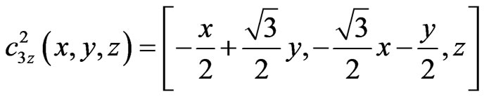

 represents the symmetry operation that a point
  in a yarn segment is converted into a point after equal sign.
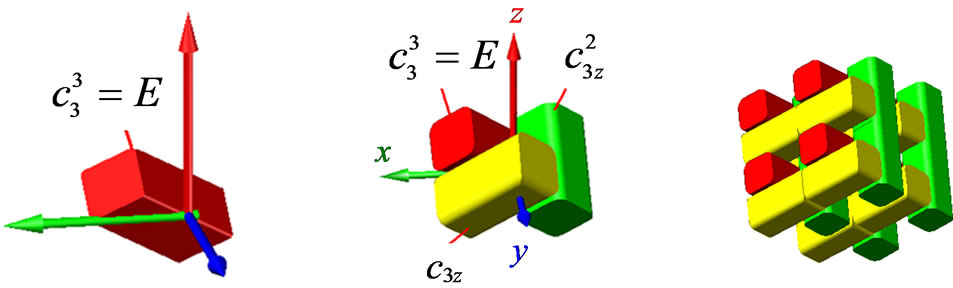
Applying symmetry operations of point group C to the yarn segment shown in Figure 1(a), a kind of combination of yarn segment, as shown in Figure 1(b), can be obtained, which is the representative volume unit for deriving new 3D braided geometry structure.
3. 3D Braided Geometry Structure Content with Space Group Symmetry
3.1. Space Simple Hexagonal Lattice Corresponding to Space Group R3
A simple hexagonal lattice (shown in Figure 2) described by crystal symmetry group is coordinated with the space group C3. The deduced unit cell (shown in Figure 1(b)) as a lattice point is put into the hexagonal lattice, and a new cross geometry structure (shown in Figure 3) with continuous yarn can be obtained considering the continuity of the yarn.
3.2. Translation Symmetry Operations Corresponding to Space Group R3
In the xyz coordinate system, translation symmetry operation is .
.
4. Geometry Structure and Processing of the New Three-Dimensional Braided Material Corresponding to the Space Group R3 Symmetry New unit cell of three-dimensional braided geometric structure can be deduced by Space group symmetry operations. The internal geometric structure of possible three-dimensional braid can be obtained by translational symmetry operation for the unit cell. In the actual braided process, boundary yarn is continuous. After considering its rules, a new three-dimensional braided geometric structure can be grasped (shown in Figure 4).
 (a) (b) (c)
Figure 1. Deducing 3D braided geometrical structure unitcell with space point group R3. (a) A yarn segment; (b) An unit-cell corresponding to point group R3; (c) The rhombohedron usual unit-cell.
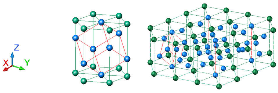
Figure 2. Space hexagonal lattice.
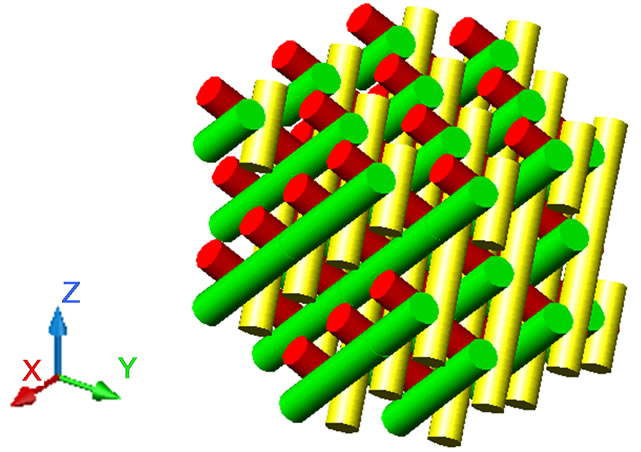
Figure 3. A new continuous yarn geometrical structure.
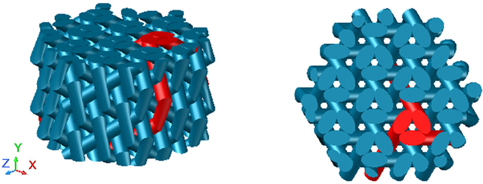
Figure 4. A new three-dimensional braided geometric structure.
To get this new three-dimensional woven material, the motion law of braided yarn carriers must be researched.
Point position shown in Figure 5 is arranged with movably braided yarn carriers, the basic braided yarn array is composed of braided yarn carriers.
Braided yarn carriers in the same orbit are in a group. There are two groups in total, named as a and b respectively. In the braiding process, the trajectory of yarn carrier in the same orbit does not change. Once all yarn carriers in a group move along the arrow direction, a braiding cycle is finished.
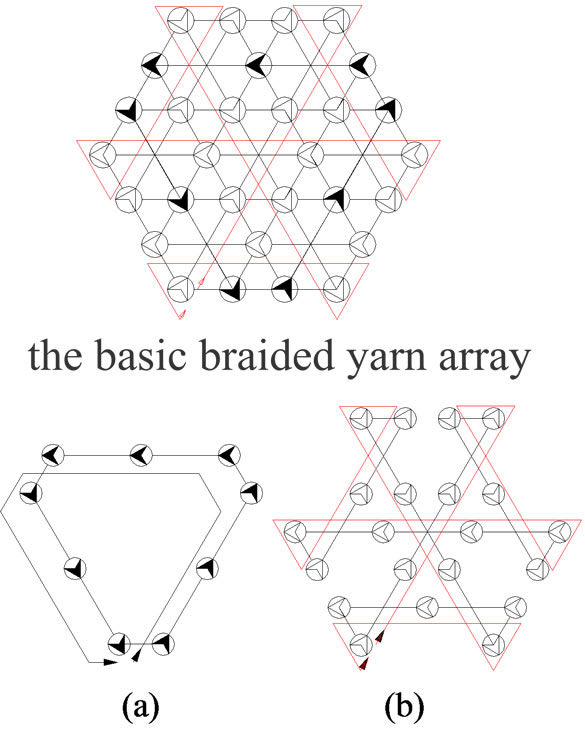
Figure 5. Yarn carrier array and the movement trajectory of the same group yarn.
The axis of each group of yarns in the three-dimensional braid is straight, and only bending at the boundary (Figure 6).
Different groups of yarns cross in space eventually form a new three-dimensional braided geometry structure.
5. The Geometric Analysis Model of the New Three-Dimensional Braided Materials
The new 3D-braided geometric structure is expected for the production of a new three-dimensional braided composite perform, as a new three-dimensional braided material, its performance prediction is an important part of basic research.
The properties of braided materials can be used in different geometric analysis model. In 1990s, the equivalent theory of 3D braided materials microstructure geometry was an effective solution to the problems in engineering applications. Ko et al. proposed the Fabric Geometric Model(FGM) [15]; Ma et al. proposed the “*”-type model of a representative unit cell [16]; Yang et al. proposed fiber tilt model based on laminate theory [17]; Du et al. gave the division of the unit cell under different assumptions and model structure. After in depth study of mesoscopic geometric structure of the unit cell [17,18]; Wu Delong proposed three-cell model [19]. Based on the geometric structure of the unit cell the analysis model is widely used and to achieve the ideal predicted results on mechanical properties.
The new three-dimensional braided material is the unit cell deduced according to space group symmetry operation. And the unit cell geometrical analysis model is more reasonable to analyze its performance. Slight difference of unit cell division method with the traditional method: full yarns are used in unit cell boundary in the geometric model of the new fabric; adjacent unit cell consists of full yarns mosaic instead of the traditional yarn center line segmentation (shown in Figure 7). The advantage of the method of this division is: maintenance of the full symmetry of the unit cell on the premise of non-affect to the geometry described; group representation theory to study the mechanical properties of the material can be used in the follow-up study.
5.1. Basic Hypothesis
1) The cross section of braided yarn in braided materials is rhombus (Figure 8) and the braided yarn is sufficiently supple.
The geometric distortion can be generated with the change in load.
2) Braiding process is stable and braiding geometry is consistent.
3) Internal unit cells account for the vast majority of the braided materials; as the cross-sectional size increases, the influence of the surface structure should be ignored.
4) Internal unit cell, the final cross-section of each yarn is extruded as shown in Figure 9 geometry by the lateral loads from different directions. The degree of lateral compression will affect the size of the fiber volume percent.
In extreme cases, the lateral extrusion of yarn will reach congestion (shown in Figure 10), and at this time fiber volume percentage of the 3D braided will reach the highest. But this time, there exists difficulty in substrate penetration, which is not conducive to improving the performance of the material, and thus three-dimensional woven composite fiber volume percentage should have the best range.
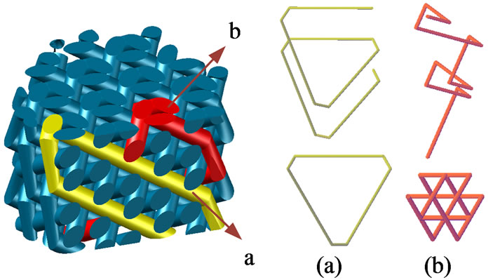
Figure 6. The different groups representation yarns in the new three-dimensional braid.

Figure 7. Three adjacent unit-cell in braided material.
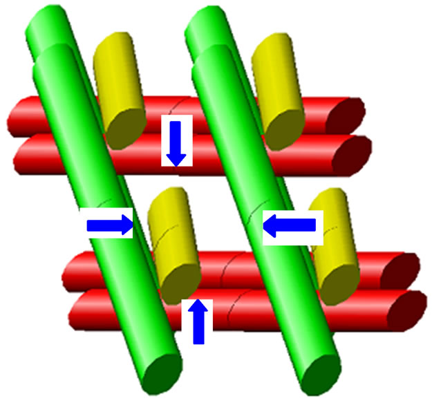
Figure 8. The diagram of internally yarn lateral extrusion.
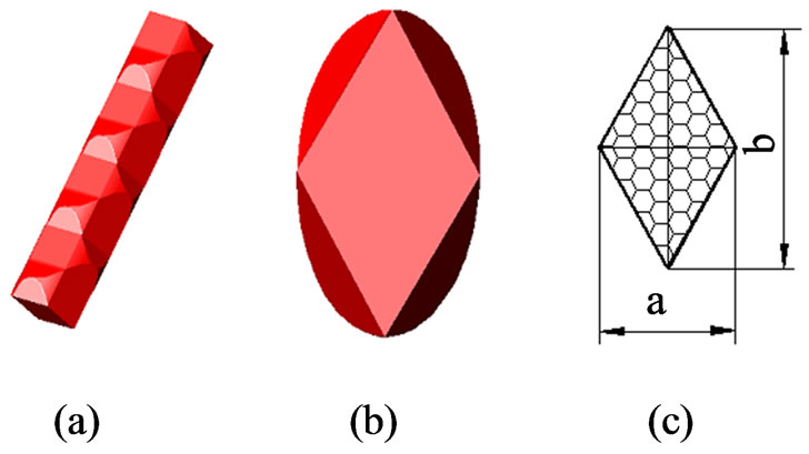
Figure 9. The approximation of internally yarn geometry.
 (a) (b)
Figure 10. The rhombohedron gap region formed by the intersection. (a) The rhombohedron gap filled situation (b) the cross section of braiding yarn by limit matter.
5.2. Geometry Model of 3D Braided Materials and the Fiber Volume Percentage
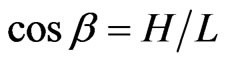
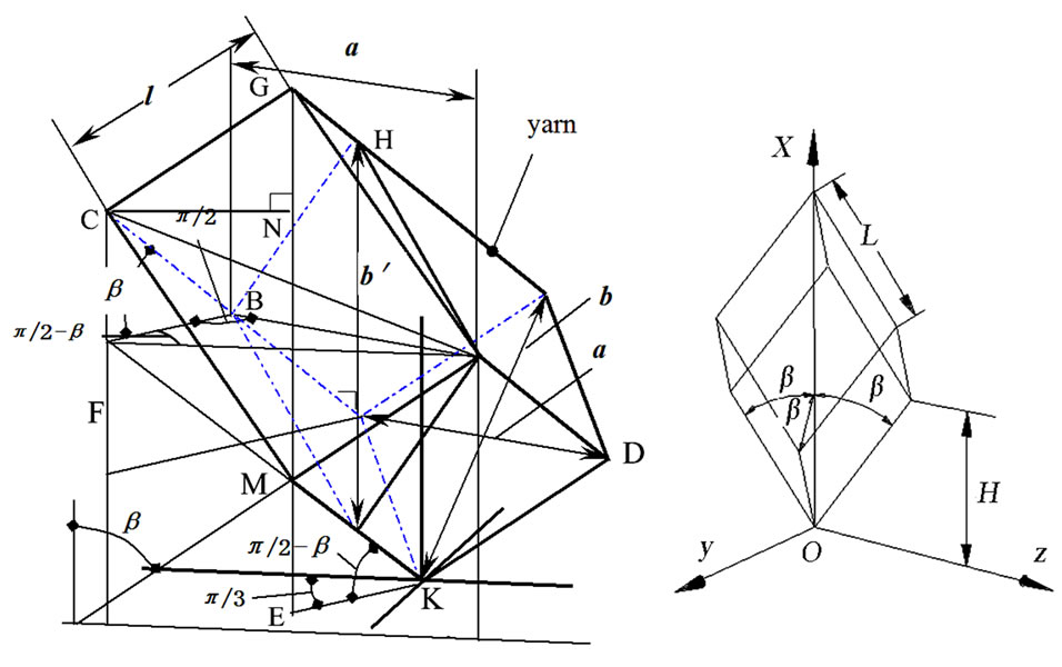
1) Rhombohedron conventional unit cell volume , Cartesian coordinates of the reference to Figure 11, set a unit cell side length L, z direction diagonal length 4H (H is unit-cell height along the symmetry axis of the direction), braid angle as
  (i.e. yarn axis and the Z-axis angle), Rhombohedron conventional unit cell volume calculated as follows:
 (1)
(1)
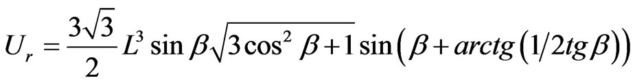 (2)
(2)
 (a) (b)
Figure 11. The relationship of Simplify yarn geometry parameters in the given coordinate system. (a) The geometric and the positional relationship of the yarn segment in braided material; (b) Coordinate system.
2) Yarn factor ε and the cross-sectional area of the reduction factor λ;
Yarn factor ε reflects the size of the yarn fiber volume percentage. Cross-section reduction factor λ represent yarn geometry deformation on the influence degree of the equivalent cross section by yarn braiding processing.
Yarn matter factor is defined as:
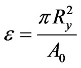 (3)
(3)
 represents the radius of the circular knitting section of yarn, and
 (4)
(4)
It is determined by the yarn linear density ( = Texy/1000) and the fiber density
  (g/cm3) [5]
To untwisted yarn and different twist yarn, the numerical is different. Twistless yarn fiber volume percent maximum is:
 (5)
(5)
A represents the yarn reduction sectional area, after the geometry changes in braided materials, assume a circular cross section of the yarn in the braiding process only has sliding between the fibers, before and after deformation of the fiber cross-sectional area of the yarn does not change, the percentage remains constant, and a crosssectional view of the yarn is not changed, there is
 (6)
(6)
A is the two diagonal length of yarn diamond cross section In the Rhombohedral space area, with the matter load increasing and Yarn deformation, the deformation of the gap will eventually be filled up, and at that time the fiber volume percent maximize. Reflected in the yarn crosssection reduction coefficient λ.
 (7)
(7)
3) Rhombohedral unit cell edge length L and yarns volume in unit cell 
From Figure 11 the following relation can be deduced,
 ,
,  ,
,
 ,
,
 ,
,
 (8)
(8)
Rhombohedral unit cell edge length can be assumed as L,
 (9)
(9)
The total volume of the 12 yarn segments in the rhombohedral unit cell can be assumed as ,
,
 (10)
(10)
Yarn fiber volume percentage can be assumed as , The total volume of the fibers is
 (11)
(11)
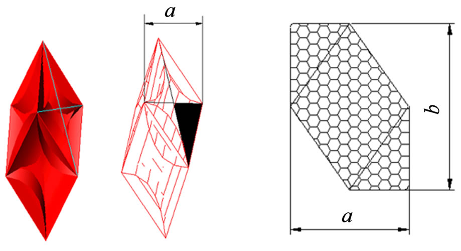
4) yarn geometric parameters after deformation a, b and 
According to previous assumptions: the yarn is supple enough; matter force is sufficient; different braid angle  corresponds to the same kind of cross-sectional geometry with different cross-sectional dimension (Figure 12).
Reference to Figure 13, the parameters A and B can be derived. Figure 13(b) is the cross-section of a rhombohedral unit cell perpendicular to the Z-axis direction, this figure meets the symmetry of point group .
.
The relationship between A and B is derived as follows:
 (12)
(12)
Braiding angle  of braided yarn (Figure 13(c)). So
 (13)
(13)
The relationship of the parameters a and b
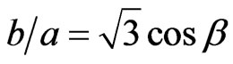 (14)
(14)
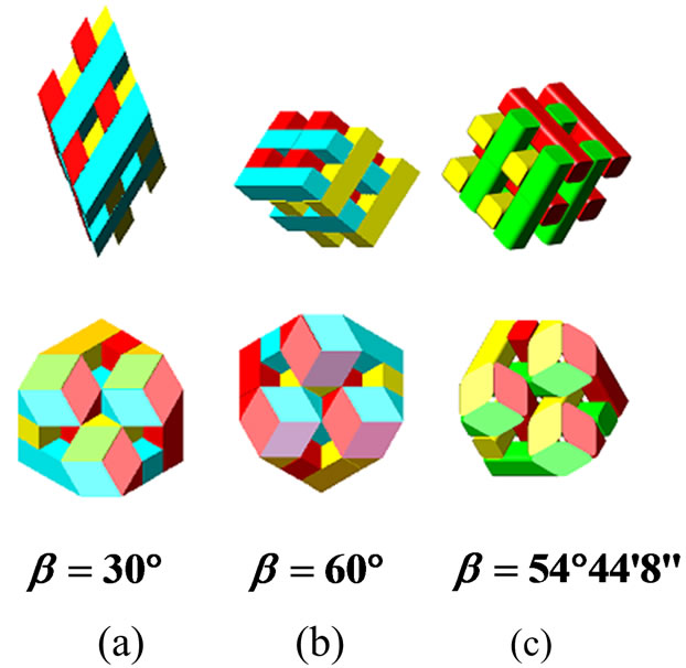
Figure 12. Different braiding angle corresponding to the same geometric shape of cross-sectional.
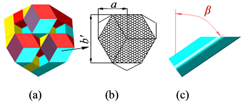
Figure 13. Derivation of the yarn cross-section parameters.
5) The fiber volume percentage . It can be expressed as:
 (15)
(15)
 is the maximum of the fiber volume percentage.
When the circular cross section of the yarn did not change, the volume percent of the fibers is at minimum
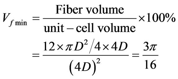 (16)
(16)
6) The value of the percent fiber volume :
:
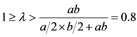
The smaller the braid angle is, the more difficult the matter process is to achieve. The braiding process also need to maintain a certain tension, corresponding to the percentage of lower fiber volume, in fact, this situation is difficult to form a dense braid. The greater the braid angle corresponds to a higher percentage of fiber volume. Fiber volume percentage will not achieve unidirectional yarn aggregate value B under limit congestion state, while according to the formula (6 - 10) we can see, the yarn cross-section reduction factor in the limit state A is 0.8. Braid angle take a value close to A, the yarn is difficult to bending deformation and difficult to achieve the congestion state; Decreases with the braid angle, yarn is prone to bending, but difficult to achieve the process of packing, the braided material is only dependent on the yarn tension weaving, the corresponding braided material because of its loose structure, the percentage of fiber volume is low. Increasing the braid angle, the braided material is not only easy to achieve the process of packing , but also easy to achieve a higher percentage of fiber volume. In the same packing force, the percentage of fiber volume increases with the braid angle.
As shown in Figure 14, fiber volume percentage results of the new three-dimensional braided material is derived by the formula (15). If the yarn cross-section reduction factor is not changed, the percentage of fiber volume almost does not change with the braid angle variation. Taking into account the yarn cross-sectional will change during the actual packing process, the curve in the figure is the simulation results with the consideration of the above factors.
According to the above analysis, this curve is the trend of the fiber volume percentage with the change of braid angle. The shaded area is the range of possible values for the percentage of volume of the composite fiber.
6. Conclusion
A novel geometry structure of unit cell is deduced from the point group  corresponding to symmetry operations. By transforming the unit cell with symmetry of space group R3, A new 3D braided geometry structure is obtained. The braided technology corresponding to this geometry structure is studied. 3D braided material fiber volume percentage and its variation tendencies are predicted by means of the established geometric model. Some new 3D braided preforms with a high performance could be obtained by optimizing the geometric parameters which have higher fiber volume percentage than traditional three-dimensional braided material. Prelimi-

Figure 14. The value of fiber volume percentage.
nary studies indicate that its geometry structure is stabler, and that the mechanical properties of corresponding braided material are better than those of the traditional three-dimensional braided material.
REFERENCES
- A. P. Mouritz, M. K. Bannister, P. J. Falzon, et al., “Review of Applications for Advanced Three-Dimensional Fibre Textile Composites,” Composites: Part A, Vol. 30, No. 12, 1999, pp. 1445-1461. http://dx.doi.org/10.1016/S1359-835X(99)00034-2
- X. M. Wang and Y. F. Xing, “Developments in Research on 3D Braided Composites,” Acta Aeronautica Et Astronautica Sinica, Vol. 31, No. 5, 2010, pp. 914-927.
- Y. Q. Wang and A. S. D. Wang, “Spatial Distribution of Yarns and Mechanical Properties in 3D Braided Tubular Composites,” Applied Composite Materials, Vol. 4, 1997, pp. 121-132
- W. Zhang, X. Ding and Y. L. Li, “Calculation and Design of Parameters for Four-step 3D Braided Preform with Complex Rectangular Cross Sections,” Journal of Industrial Textiles, Vol. 38, No. 2, 2008, pp. 139-150. http://dx.doi.org/10.1177/1528083707087838
- Y. Sun, J. L. Li and L. Chen, “Topology Optimization of the Fiber Microstructure of 3D Multidirectional Braided Composites,” Journal of Textile Research, Vol. 28, No. 10, 2007, pp. 46-48.
- K. Xu and X. W. Xu, “Microstructure Model of 3D 5-Directional Rectangular Braided Composites,” Journal of Nanjing University of Aeronautics & Astronautics, Vol. 40, No. 2, 2008, pp. 168-172.
- J. C. Li and L. Chen, “Parameterized Unit Cell of 3-D Five-Directional Braided Composites,” Journal of Tianjin Polytechnic University, Vol. 27, No. 5, 2008, pp. 1-3.
- J. Y. Liu and L. Chen, “Microstructure of 3D Six-Directional Braided Preforms,” Journal of Tianjin Polytechnic University, Vol. 25, No. 6, 2006, pp. 5-8.
- D. S. Li, Z. X. Lu and L. Chen, “Microstructure Analysis of 3-Dimensional 7-Directional Braided Structure,” Acta Materiae Compositae Sinica, Vol. 23, No. 1, 2006, pp. 135-141.
- J. L. Li and Y. Sun, “Microstructure of the Two-Step Rectangle 3D Braided Composites,” Acta Materiae Compositae Sinica, Vol. 19, No. 4, 2002, pp. 69-75.
- W. Feng, W. S. Ma, “Group Theory Analysis of Braided Geometry Structures,” Chinese Science Bulletin, Vol. 50, No. 21, 2005, pp. 2529-2533.
- W.-S. Ma, J.-X. Zhu, Y. Jiang and C.-K. Yang, “3D Braided Geometric Structures Derived by Space Groups,” Journal of Materials Science & Engineering, Vol. 28, No. 5, 2010, pp. 653-657,687.
- R. H. Wang and K. X. Guo, “Crystallographic Symmetry Group,” Science Press, Beijing, 1990, p. 207.
- W. S. Ma and X. Z. Ren, Chinese Science Bulletin (Chinese Version), Vol. 56, 2011, pp. 598-603. http://dx.doi.org/10.1360/972010-1937
- F. K. Ko and C. M. Pastore, “Structure and Properties of Integrated 3D Fabric for Structural Composites,” American Society for Testing Material, 1985, pp. 428-439.
- C. L. Ma, J. M. Yang and T. W. Chou, “Elastic Stiffness of Three-dimensional Braided Textile Structural Composites,” American Society for Testing Material, 1986, pp. 404-421.
- J. M. Yang, C. L. Ma and T. W. Chou, “Fiber Inclination Model of Three-Dimensional Textile Structural Composites,” Journal of Composite Materials, Vol. 20, No. 5, 1986, pp. 472-484. http://dx.doi.org/10.1177/002199838602000505
- G. W. Du, T. W. Chou and P. Popper, “Analysis of Three-Dimensional Textile Preforms for Multidirectional Reinforcement of Composites,” Journal of Materials Science, Vol. 26, No. 13, 1991, pp. 3438-3448. http://dx.doi.org/10.1007/BF00557129
- G. W. Du and F. K. Ko, “Unit Cell Geometry of 3-D Braided Structures,” Journal of Reinforced Plastics and Composites, Vol. 12, No. 7, 1993, pp. 752-768. http://dx.doi.org/10.1177/073168449301200702