Circuits and Systems
Vol.5 No.6(2014), Article
ID:47487,7
pages
DOI:10.4236/cs.2014.56017
Research of an Efficient LED Lighting Driver Based on Boost-Buck Converter
Renbo Xu1,2, Yongzhi Li3, Lixin Zhong4, Jiaming Liu5
1Department of Electronics, Hunan Information Institute, Changsha, China
2School of Physics and Electronics, Central South University, Changsha, China
3Hunan Electric Power Transmission and Substation Reconnaissance and Design Consulting Co., LTD., Changsha, China
4The First Middle School in Taoyuan, Changde, China
5Changsha Reform School, Changsha, China
Email: maple_red1109@163.com
Copyright © 2014 by authors and Scientific Research Publishing Inc.
This work is licensed under the Creative Commons Attribution International License (CC BY).
http://creativecommons.org/licenses/by/4.0/


Received 5 April 2014; revised 8 May 2014; accepted 13 June 2014
ABSTRACT
Boost-Buck converter is widely used in LED lighting drivers. In this paper, Boost-Buck main circuit related characteristics are firstly discussed, and then a new Boost-Buck high power efficient double loop control strategy is built by adopting error amplifier and integrator control method. It is demonstrated that the new system has many advantages such as high efficiency, fast response, strong anti-interference, good stability after analyses and simulations of its working dynamic characteristics.
Keywords:LED Lighting, Boost-Buck, Double Loop Control, Efficient and Stable

1. Introduction
In recent years, as the progress of light emitting diode (LED) technology, high-power LED has more and more applications such like cellular phone, pocket pc and LCD (Liquid Crystal Display), TV, etc., which creates a huge market demand for LED driver. However, requirements such as high power factor, long life time, low cost, switch protection, accurate current control and high luminous efficiency pose challenges to the design of LED driver circuit. One of the most commonly used high-power LED is driven at 350 mA and LED manufacturers are constantly working on driving LED at higher output current so that it can provide sufficient light output for broader lighting applications [1] [2] .
This brings about the need for high-power LED driver that can deliver and regulate LED current in a power efficient manner. Among all kinds of LED drivers, switch mode power converters are common choices for high-power LED driver due to its better efficiency [3] . In general, DC-DC PWM (Pulse-Width Modulation) converters for LED have three basic types: Buck, Boost and Buck-Boost. Some other topologies like Fly-back, Boost-Buck, Single-End Primary Inductance Converter (SEPIC) etc. are all derived from the three basic topologies above [4] . In order to study the performance of DC-DC PWM converters, we take Boost-Buck type for example, as shown in Figure 1. Unlike conventional LED drivers, it could be applied to both low and high voltage cases. And it is widely used in car applications because the car power supply voltage is changeable.
Considering that the ripple of LED current will impact the luminous flux and consequently the luminous efficiency, the peak current mode (PCM) control is chosen in Figure 1. It can be known from the analysis that PCM control technique of Boost-Buck converter features fast transient response and high stability [5] [6] . But it only control the forward peak current of LED, not the average current, it can’t satisfy the accurate regulation of luminance. In this paper, a novel high power-efficient PWM controller for average current is proposed.
The basic circuit description of Figure 1 is described in Section 2. The new high-power LED driver with power-efficient accurate output current control is derived in Section 3, and Section 4 presents the simulation and experimental results.
2. Circuit Description
The DC-DC converters in the open loop usually use Pulse Width Modulation to control the switch to regulate the output voltage [7] -[9] . The duty ratio is a proportional relation to the input and output voltage. But there are some factors like input voltages disturbances and ripples cause the output voltage unstable. In order to deal with the problem, a feedback loop is added to the system.
The general idea behind it is to adjust voltage or current through closed loop control. And the DC-DC converter under PCM is operated in Continuous Conduction Mode (CCM). A sensing resistor placed in series to the high-power LED is used to sense the current and convert it to a feedback voltage for system control [10] -[13] . To prevent the sensing resistor to consume too much power and gain high power efficiency, a small resistance is chosen. After the output current flowed through the sensing resistor, the sensing feedback voltage can be gained. Then the error signal is acquired after the reference voltage compared with the sensing voltage and passed by the RS flip-flop. And the output signal of the driver becomes the control signal of power MOS switches and realizes the peak current control.
The complicated Boost-Buck converter could be considered as a single Boost converter connected with a single Buck converter. From the Boost-Buck converter diagram in Figure 1, we can see that a conductor, MOS switch S1, a diode and a capacitor form the Boost part, and the Buck part are constituted with the other components except for the comparator and RS flip-flop. According to the operation of Boost-Buck converter, the relationship between input voltage  and output voltage
  can be described as [14] :
 (1)
(1)
In the Equation (1), D is the steady duty ratio of MOS switch, and we can regulate the output voltage through controlling the duty ratio D.
3. The Proposed Constant Output Current Circuit
From the analysis of Boost-Buck converter features under peak current mode it can be known that the converter has high stability, fast transient response and high efficiency. But it can’t satisfy the accurate regulation of luminance, because the converter only controls the forward peak current, not the average current [15] . In order to control the average current of LED precisely, a new driver called as double-loop current-mode control technique is proposed through adding a current outer loop into the peak current mode control technique, as shown in Figure 2. The error amplifier block and the integrator block constitute an outer loop, and the voltage comparator, the RS flip-flop and the driver form inner loop.
From the system block diagram in Figure 2, we can see that there is a sensing resistor Rs to sense the output current. The operation of the circuit is as follows. Metal Oxide Semiconductor switches S1 and S2 are controlled
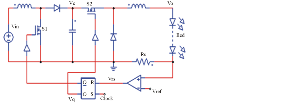
Figure 1. LED Boost-Buck converter diagram.
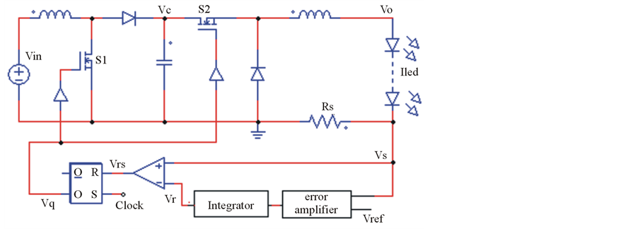
Figure 2. The proposed LED driver with double-loop current-mode control.
by the basic RS flip-flop. There are two repeated phases. During phase 1, the input S of RS flip-flop is high level, and the output Q is high level, then the switch S1 is turned off and S2 is turned on. After the output current flowed through the high power LEDs and Rs, the sensing feedback voltage Vs can be acquired. The control voltage signal Vrs between the integral voltage Vr of error value and the sensing feedback voltage Vs is obtained to control the RS flip-flop. Then the output of RS flip-flop control the MOS switches S1, S2 and regulate the output current accurately. When the sensing feedback voltage Vs moves upward and surpasses integral voltage Vr, the circuit enters phase 2. The input R of RS flip-flop changes to high level, and the output Q is low level. Then the MOS switches S1 and S2 converse. The sensing feedback voltage Vs moves down quickly until the next clock in input S comes and the circuit enters phase 1 again. Then the two phases are repeated continuously and the working waveforms are shown in Figure 3.
Different with the Boost-Buck converter the new reference voltage in the double-loop current-mode control  is
is
 (2)
(2)
By using the integral value of error value between reference voltage and sense voltage it regulates the control voltage to eliminate the steady error of the average current. Besides, the new driver could be applied in wide frequency and the minimum and maximum frequency could be described in Equations (3) and (4).
 (3)
(3)
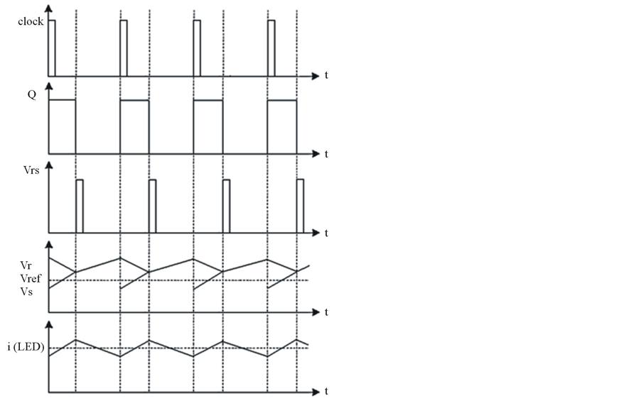
Figure 3. The working waveforms of the proposed driver.
 (4)
(4)
In the Equations (3) and (4), is the diode conduction voltage drop, ![]() is the actual turn-off time,
is the actual turn-off time,  and
and  are the minimum and maximum efficiency respectively.
As a result of double-loop current-mode control technique, the driver provides a precise constant average output current for the LEDs and gets high power efficiency. Moreover, the proposed converter operating in CCM has many better performances such as variable input voltages, wide frequency bandwidth and high stability.
4. Simulation and Experimental Results
In the section, to study the proposed controller without losing generality, the control performance of DoubleLoop Current-Mode control technique is verified by time-domain simulation, and based on that, the proposed LED driving system has been developed to implement a serial of comparative experiments. The results show the advantages and validity of the new driver, such as excellent dynamic performance and good robustness.
In the driving simulation, the input voltage Vin is commonly used 12 V,the reference voltage Vref is 0.035 V and the sensing resistor is 0.1 Ω. The clock signal is amplitude of 1 V, frequency of 200 kHz. The LED component is replaced by a voltage of 3 V and a resistor of 1.2 Ω, as shown in Figure 4.
Figure 5 is the waveforms of Boost-Buck converter. The output voltage Vo, LED current Iled, power MOSFET gate driving signal Vq and boost output voltage Vc etc. are shown in the figure. The curves showed that the ideal CCM operationis well realized. From the simulated waveforms, we can see that the LED current Iled is changed with the driving signal Vq. When Vq is high level, Iled moves up to 350 mA. Then Vq converses to low level, Iled moves down to 300 mA until Vq is changed to high level and Iled moves up again. The feedback signal Vrs is also consistent with the theory well. Moreover, the boost output Vc approaching 24 V surpasses the input Vin much and the output Vo is 3.50 V below Vin, which realizes the operation of the boost-buck converter.

Figure 4. LED equivalent circuit.
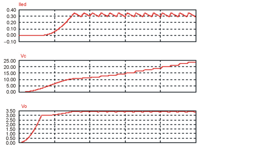
Figure 5. Simulated waveforms in Boost-Buck converter.
Figure 6 is the waveforms of the proposed Double-Loop Current-Mode driver in CCM. From the figure, we can see that boost output Vc is also much higher than the input voltage Vin, which makes the operation of boost-buck converter well verified again. The output voltage Vo is more stable than that in boost-buck converter and the LED average current is equal to the reference current 350 mA. However, in the Boost-Buck converter, the average current is near 330 mA blew the reference current. It can be concluded that the new control technique eliminates the steady error of the average current more precisely by adding a outer loop. With the error amplifier and integrator introduced, the new reference voltage Vr is no more a linear voltage source. And it is also seen that the current flowing LED in the new driver moves up more steadily and slowly, which is a good protection for the switches.
Totest current regulation ability of the proposed LED driver under different power supply voltages, three voltages of 6 V, 12 V and 24 V are used. The preset output average current is 350 mA. Measurement results are shown in Figure 7 and prove that the output current for the same reference voltage Vref dose not change significantly when supply voltage Vin is changed. It is to say that the proposed LED driver could be applied to both low and high supply voltage cases.
All the test results are consistent with expectations well.
5. Conclusion
In this paper, a new power-efficiency high-power LED driver that could regulate the average output current precisely by integrating the error voltage between reference voltage and sensing voltage is proposed. The performance of the new control technique is verified by time-domain simulation and tested on the experimental circuit board. Measurement results show that the average output current is equal to the preset current 350 mA, and the driver can be used in different input voltages cases such as 6 V, 12 V and 24 V etc. The simulated waveforms
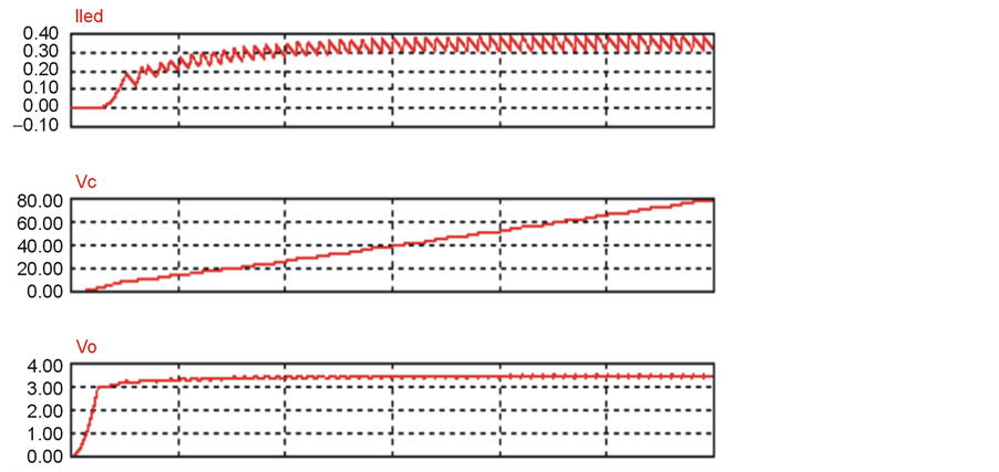
Figure 6. Simulated waveforms in the proposed driver.
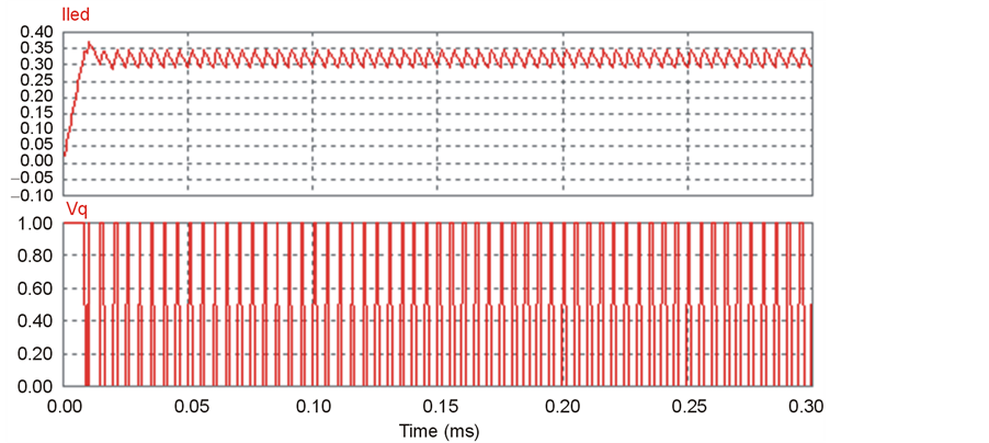
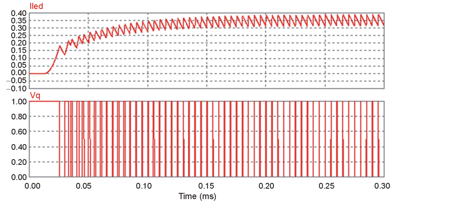
Figure 7. LED current curves under different power supply voltages.
and results conform that the proposed driver can get a reasonable LED average output current accuracy and good regulation. Besides, the new driver also provides protection to MOS switches.
References
- Lu, J.Y. and Wu, X.B. (2011) A Novel Multiple Modes PWM Controller for LEDs. IEEE Proceedings, Circuits, Devices and Systems, 1767-1770.
- de Britto, J.R., Demian Jr., A.E., de Freitas, L.C., Farias, V.J., Coelho, E.A.A. and Vieira Jr., J.B. (2012) A Proposal of Led Lamp Driver for Universal Input Using Cuk Converter. IEEE Publication, 2640-2644.
- Sauerlander, G. (2007) Solving High-Voltage Off-Line HB-LED Constant-Current Control-Circuit Issues. Applied Power Electrons Conference, APEC 2007-Twenty Second Annual IEEE, Anaheim, 25 February-March 1 2007, 1316-1318.
- Middlebrook, R.D. (2013) Topics in Multiple-Loop Regulators and Current Mode Programming. IEEE Transactions on Power Electronics, PE-2, 109-124. http://dx.doi.org/10.1109/TPEL.1987.4766345
- Zane, R. and Maksimovic, D. (2013) Nonlinear-Carrier Control for High-Power-Factor Rectifiers Based on FLYBACK, CUK or SEPIC Converter. Proceedings of IEEE APEC, 814-820.
- van der Broeck. H., Sauerlander, G. and Wendt, M. (2007) Power Driver Topologies and Conrol Schemes for LEDs. Applied Power Electronics Conference, APEC 2007-Twenty Second Annual IEEE, Anaheim, 25 February-March 1 2007, 1319-1325.
- Rico-Secades, M., Calleja, A.J., Ribas, J., Corominas, E.L., Alonso, J.M., Cardesin, J. and Garcia, J. (2013) Evaluation of a Low Cost Permanent Emergency Lighting System Based on High Efficiency LEDs. IEEE-IAS-2013 38th Annual Meeting, 21-25.
- Bryant, B. and Kazimierczuk, M.K. (2012) Modeling Closed-Current Loop of PWM Boost DC-DC Converters Operating in CCM with Peak Current-Mode Control. IEEE Transactions on Circuits and Systems I: Regular Papers, 52, 2404-2412.
- Ronat, O., Green, P. and Ragona, S. (2013) Accurate Currentcontrol to Drive Highpower LED Strings. IEEE APEC 2013, 2376-2380.
- Steigerwald, D.A., Bhat, J.C., Collins, D., Fletcher, R.M., Holcomb, M.O., Ludowise, M.J., Martin, P.S. and Rudaz, S.L. (2013) Illumination with Solid State Lighting Technology. IEEE Journal of Selected Topics in Quantum Electronics, 8, 310-320.
- Nishikawa, M., Ishizuka, Y., Matsuo, H. and Morihori, K. (2010) Static Characteristics of a Drive Circuit for LED with Constant-Current Control and Constant-luminance Control. IEICE Technical Report EE2010-72(2011-02), 67-72.
- Nishikawa, M., Morihori, K., Ishizuka, Y. and Matsuo, H. (2013) Static Characteristics of A Drive Circuit for LED with Constant-Current Control. Annual Conference of IEI-J, 251.
- Cook, B. (2012) New Developments and Future Trends in High-Efficiency Lighting. Engineering Science and Education Journal, 9, 207-217.
- Greenfeld, F. (2013) White LED Driver Circuits for Off-Line Applications Using Standard PWM Controllers. Intersil Corporation, Application Note, 12-17.
- CUK, S. and Middlebrook, R.D. (2011) Advances in Switched-Mode Power Conversion. IEEE Transactions on Industrial Electronics, IE-30, 10-19.