Journal of Modern Physics
Vol.4 No.1(2013), Article ID:26699,8 pages DOI:10.4236/jmp.2013.41003
Seismic Signal and Data Analysis of Rock Media with Vertical Anisotropy
1The James Frank Institute and Department of Chemistry, The University of Chicago, Chicago, USA
2School of Electronics Engineering, Xi’an University of Post and Telecommunication, Shaanxi, China
Email: *m-zhao@uchicago.edu
Received November 2, 2012; revised December 1, 2012; accepted December 10, 2012
Keywords: Anisotropy; Rock Media; Seismic Signal; Data and Analysis
ABSTRACT
This paper is concerned with anisotropic effects on seismic data and signal analysis for transversely isotropic rock media with vertical anisotropy. It is understood that these effects are significant in many practical applications, e.g. earthquake forecasting, materials exploration inside the Earth’s crust, as well as various practical works in oil industry. Under the framework of the most accepted anisotropic media model (i.e. VTI media, transverse isotropy with a vertical axis symmetry), with applications of a set of available anisotropic rock parameters for sandstone and shale, we have performed numerical calculations of the anisotropic effects. We show that for rocks with strong anisotropy, the induced relative depth error can be significantly large. Nevertheless, with an improved understanding of the seismic-signal propagation and proper data processing, the error can be reduced, which in turn may enhance the probability of forecasting accurately the various wave propagations inside the Earth’s crust, e.g. correctly forecasting the incoming earthquakes from the center of the Earth.
1. Introduction
The properties of mechanical waves in different media have been investigated extensively and reported in literature, for example, the quality detection of concrete structures, as reported by Larose etc. [1]. These studies were aimed primarily at achieving an improved understanding of the physical properties and geometric structure of the propagation media. In seismic explorations, time-depth relation from seismic reflection data was used for time-depth conversion, so as to understand the geological structure of the Earth’s interior. This approach is useful in evaluating the porosity and permeability of rock layers and searching for oil reservoirs.
Elastic anisotropy is arguably one of the most important phenomena in the Earth’s interior [2]. It has been reported that rock anisotropy can significantly influence the phase velocity and energy velocity, as well as the reflection and transmission coefficients of elastic waves [3,4]. As a result, it distorts the velocity analysis and the Amplitude Variation with an Offset (AVO) analysis, which is one of the few existing analyses capable of direct detection of hydrocarbons [5-8]. Discussions on the effect of rock anisotropy in seismic exploration were provided by several research groups [9-11]. It was reported by Banik et al. [12] that rock anisotropy could cause discrepancies between the well-log depth and the seismically determined depth. By employing available seismic reflection data, significant efforts in accurately imaging the geological structures beneath the seafloor were made [13,14]. Numerical calculations of anisotropic effect on reflection travel-time of seismic signals were performed and reported by Fomel and Biondi [15] and by Alkhalifah and Tsvankin [16].
Nowadays, it is well understood that rock anisotropy can significantly influence the phase and energy velocities of an elastic wave, as well as the reflection and transmission (R/T) coefficients [17]. Nevertheless, a quantitative understanding of the anisotropic effects on the seismic signal and data analysis is still limited. For this reason, there has been a great interest in analyzing the effects of anisotropy in various media, so as to obtain an improved understanding of seismic reflection data, process and analyze the information, and determine, for example, when an earthquake may arrive from the Earth’s interior.
In quantitative analysis of the anisotropy effects on seismic data and signal, the accuracy of a time-depth relation is critically important, because it is closely related to the velocity analysis of seismic signals, depth estimation of reflectors, and synthesis of seismograms. A fundamental assumption in conventional velocity analysis is to treat formation-media as isotropic. But, for a seismic wave propagating in elastic anisotropic media, the magnitude and direction of its phase velocity are different from those of its energy velocity. Therefore, due to its oversimplification, the conventional velocity analysis will be insufficient for processing, interpreting, and imaging the seismic reflection data. This is especially true for cases of strong anisotropy [9,11,18,19]. In this paper, we present a study of an accurate velocity analysis and report the effects of rock anisotropy on seismic data analysis in transversely isotropic media.
2. Theoretical Background
Most geological systems can be modeled as fine layering in which the dominant wavelength of a pulse is much larger than the thickness of the individual layers [17]. Therefore, sedimentary rocks such as shale are commonly treated as being transversely isotropic [2,20]. For an elastic wave in isotropic media, the wave-front is spherical; the phase velocity is perpendicular to its wavefront, the energy velocity and the density vector are in the same direction, and the direction and magnitude of the phase velocity are the same as those of the energy velocity, as shown in Figure 1.
One class of elastic seismic waves is the so-called P-wave, which stands for primary wave. It is the fastest traveling wave compared to other elastic waves, e.g. S-waves and surface waves. P-waves can travel through various media, including the Earth’s crust, and they are recorded on seismograms when created by earthquakes. By detecting the non-destructive P-waves, it is possible to have warnings of earthquakes before they arrive, because P-waves travel more quickly than the destructive secondary waves (S-waves). Following P-waves, S-waves are the second type of wave to be recorded on an earthquake seismogram. In seismic applications, S-waves are polarized vertically and are called SV-waves, i.e. SVwaves propagating in a vertical plane. The SV-waves move vertically through the different layers of the Earth, which each exhibit different properties, and thus serve as anisotropic media.
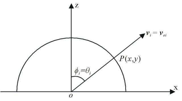
Figure 1. The relationship between phase velocity and energy velocity in xz-plane within an isotropic media.
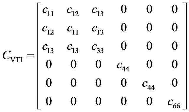
A transversely isotropic elastic medium with a vertical axis of symmetry (Figure 2) is called a VTI medium model. Despite its limitation, the VTI model offers the simplest way to account for both heterogeneity and anisotropy in subsurface formations with a generic stiffness matrix [17]
 . (1)
. (1)
For the various elements of the stiffness-matrix,  is a modulus with respect to stress and strain in the medium. Due to the transversely isotropic nature of the VTI media, our discussions may be focused purely on a two-dimensional seismic reflection wave propagating in xz-plane (see Figure 3). For the transversely isotropic rocks, the elastic moduli and anisotropic parameters are given by
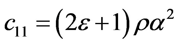 ,
, 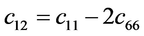 ,
, 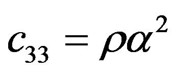 ,
,
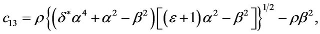
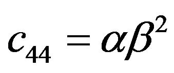 ,
,  , where,
  and
and  are the anisotropic parameters, while
  and
and  are the vertical phase velocities of P-waves and SV-waves respectively. These velocities bear no relation to anisotropic parameters and are identical to the phase velocities
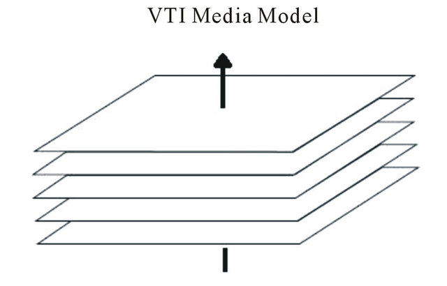
Figure 2. Transversely isotropic elastic VTI medium with a vertical axis of symmetry.
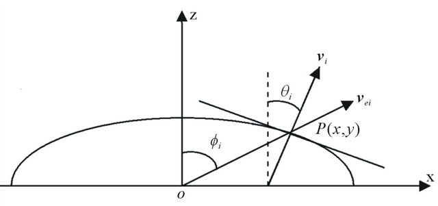
Figure 3. The relationship between phase velocity and energy velocity in xz-plane within an anisotropic media. Note that in the anisotropic media, phase angle and energy angle are not equal.
of P-wave and SV-wave in isotropic rock media.
A plane wave 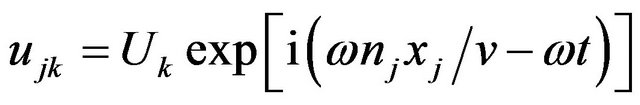 solves the Christoffel equation
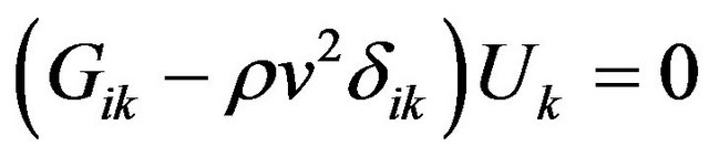 , where
  is the Christoffel matrix,
  is the phase velocity,
  is the polarization,
  is the media mass density, and
  is the unit of slowness. Based on the Christoffel equation, the phase velocities of P-waves and SV-waves in an infinite elastic VTI medium are obtained as [3]
 (2)
(2)
where,  with i =
{p, sv},  is the phase angle as shown in Figure 3,
 ,
,  ,
,
 ,
,  , and
, and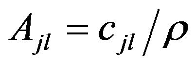 .
.
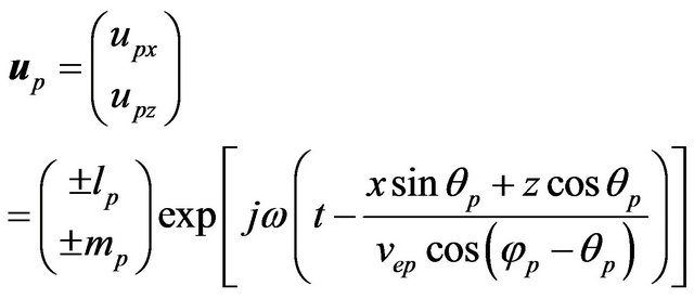
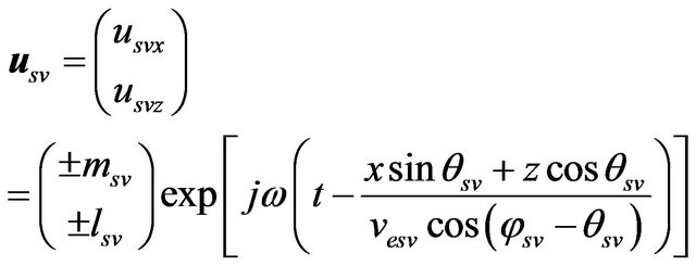
The normalized displacement vectors of Pand SVwaves can be written as [14]
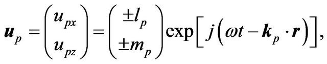 (3)
(3)
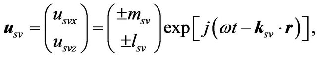 (4)
(4)
where  and
and  are the polarization coefficients. The sign of these coefficients are dependent on the anisotropic parameters and the corresponding phase angle.
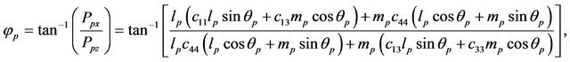
The information presented has numerous applications elsewhere as well. For example, let’s consider the case of a P-wave impinging a plane reflector, creating converted P-wave and SV-wave. This particular case involves many practical applications in oil industries, where P-waves constitute the overwhelming majority of seismic data. The seismic wavelet does not create the frequency dispersion during its propagation, so the phase velocities are constants for all frequency components of a given wavelet. It should be noted that for an elastic anisotropic medium, the wave-front is no longer symmetric. Both the phase velocity direction and its magnitude are generally different from those of the energy velocity (see Figure 3). In seismic exploration, the actual seismic wave propagates in the ray direction with energy velocity magnitude.
For a homogenous P-wave or SV-wave propagating in the ax-plane, the phase velocity can be written as
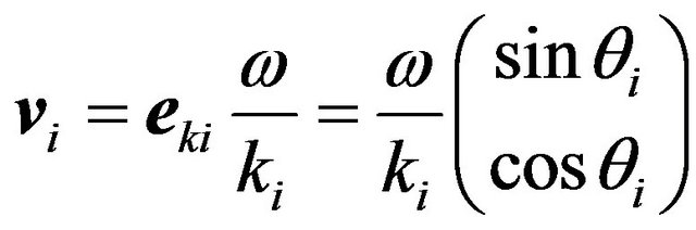 , (5)
, (5)
where,  is the unit vector of the wave-front normal. The power density flux can be written as
 , (6)
, (6)
where,  is the unit particle displacement velocity and
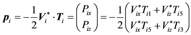
  represents the stress tensors. The xand z-components of power density flux can be written as
 , (7)
, (7)
 , (8)
, (8)
 , (9)
, (9)
 . (10)
The relationships between the energy angle and phase angle are obtained as
 (11)
(11)
 (12)
(12)
Invoking the relationship between energy and phase velocities,  , energy velocity can be expressed as [21]
 . (13)
Inserting Equation (19) into Equation (10) yields the normalized displacement vectors
 , (14)
 . (15)
3. Results and Discussions
We have performed numerical calculations for rock formations with anisotropy and selected some typical rock samples with available anisotropic parameters listed in Table 1, as reported by Thomsen et al. [22,23]. Specifically, the three samples are: 1) M-sandstone with very small anisotropic parameters; 2) C-sandstone with a weak to moderate anisotropy; and 3) M-shale with moderate to strong anisotropy.
When a P-wave propagates in the ax-plane with a plane reflector with phase velocity , energy velocity
 , and the travel-time
 , we set the horizontal distance from the source to the receiver (i.e. offset) to be 2l. The actual time-depth relation of reflector between two homogenous rock layers can be written as
 . (16)
For a weak anisotropic case, using phase velocity in place of energy velocity yields a time-depth relation for the reflector
 . (17)
Furthermore, when neglecting the effect of the anisotTable 1. Rock anisotropic parameters for Mesaverade sandstone, Mesaverade calcareous sandstone, and Mesaverade shale. In the following table  and
and  are in unit of (m/s) and
  is in unit of (g/cm3).
ropy by using vertical phase velocity  to replace the energy velocity, the time-depth relation yields
 . (18)
Using Equations (16)-(18), we have calculated the actual reflector depth (h) and the induced depth errors,  , as a function of the reflection travel-time,
  , as well as the obtained reflector depth as a function of the offset midpoint (l). Using
 , we have calculated the errors in the time-depth relation and defined the absolute percentage errors as
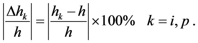 (19)
(19)
The results of calculations for the selected samples are given in Tables 2 and 3.
Now, let’s consider the propagation and reflection of a wave, as shown in Figure 4, with an observation position R. A wave leaves a source S, propagates to a point O, and then is reflected back to the surface position R. The energy incident angle  on the reflection point O is different from the phase incident angle
 . The energy angle is determined by the offset and the reflector depth, while the phase angle is dependent on the energy angle and the rock anisotropy. Because both energy and phase velocities are functions of phase angle and the rock anisotropy, the travel-time of a reflected signal varies with respect to several factors, including the reflector depth, anisotropic properties, and phase and energy angles for a given offset.
In seismic exploration, the data for the reflected seismic signal can be obtained in different moving patterns of a measurement line. Here, we assume that the
Table 2. Induced relative depth errors as a function of wave traveling time  with a fixed offset
  in neglecting anisotropy.
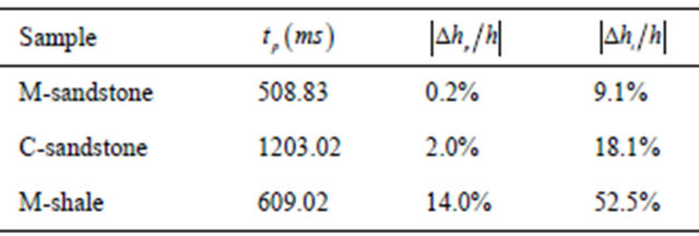
Table 3. Induced relative depth errors as a function of offset 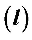 in neglecting anisotropy.
measurement line consists of one source S and N receivers , where all receivers are located in a direct line on the surface. Suppose that the measurement line rotates around the source S at a fixed-angle interval and the measurement line acquires seismic data with each rotation. Figure 5 demonstrates the rotation of the measurement line from
  to
to .
.
In the case that the measurement line is parallel to the x-axis, the measurement in acquiring seismic data can be made in the y-direction with each increment . Figure 6 shows a step-by-step measurement from
  to
to  with various reflections and the approximation in ignoring anisotropy. Figures 7 and 8 show that, the depth error
  and the relationship of depth-offset midpoint
  are independent of the y. For the same reason, if the measurement line is parallel to y-axis and moves forward in the x-axis direction, then the depth estimation error
  and the relation of depth versus offset midpoint can obtained by rotating 90˚ in space from Figures 7 and 8.
Figures 9 and 10 show that, when ignoring anisotropy, the estimated depth error and the relationship of depth-offset midpoint are symmetric in shapes with respect to the vertical axis. It reveals that by ignoring the effect of rock anisotropy on phase and energy velocities (or neglecting the difference between the energy velocity and the phase velocity), the estimated depth and the obtained relation of depth-offset midpoint are dependent on the arrangement of the measurement line. Therefore, ignoring anisotropy can distort the velocity analysis of acquired seismic signals and lead to an increased level of error for the inversed reflector depth.
For all three rock samples studied in this paper, entries in Tables 2 and 3 show that, regardless whether it is strong or weak, neglecting the rock anisotropy will lead to errors in the time-depth relation. For weak anisotropic M-sandstone, the relative errors are comparably small with  being about 0.2% and
  being about 9.1%. However, for strong anisotropic rock, such as M-shale, these errors are very significant, with
  being about 14% and
  being about 52.5%. For the case of moderate or strong anisotropy, the induced depth error may reach up to several hundred meters. Consequently, the velocity analysis of seismic
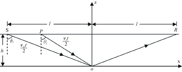
Figure 4. The propagation path of seismic reflection signal in anisotropic medium in ax-plane.
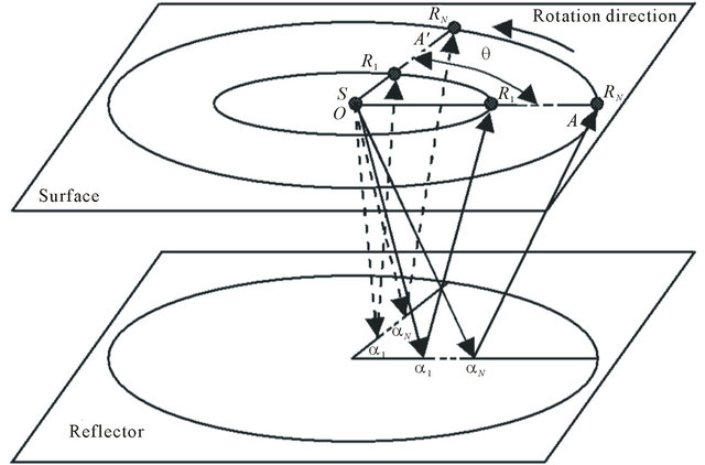
Figure 5. A measurement line rotates from  to
to  at the same angle interval each time with respect to the vertical axis.
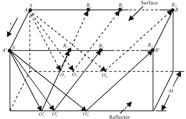
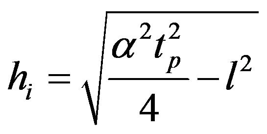
Figure 6. The depth error measurement and reflector depth hi in neglecting the anisotropy, with measurement at the interval of  in y-axis direction.
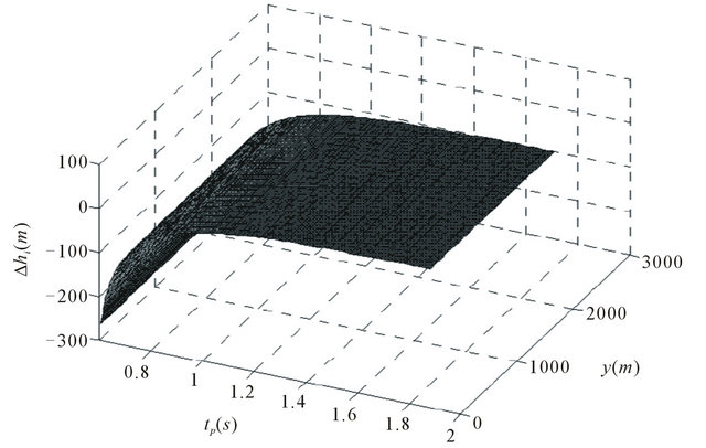
Figure 7. In neglecting the anisotropy, the relation of measurement error  versus both
  and coordinate y.
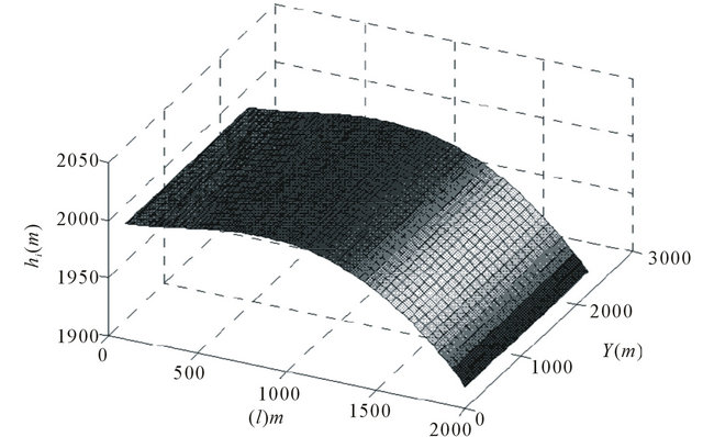
Figure 8. In neglecting the anisotropy, the relation of reflector depth hi versus both the measurement length l and coordinate y.
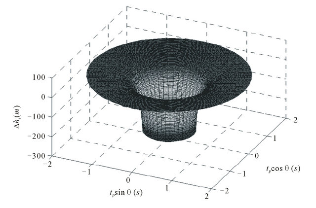
Figure 9. The depth error due to neglecting the anisotropy rotating with respect to vertical axis. θ is the rotation angle of the measurement line.
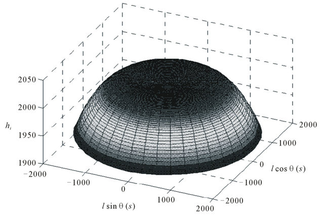
Figure 10. Reflector depth for the pattern of measurement line rotating with respect to vertical axis.
data will be significantly distorted.
4. Final Words
From Section 3, the results of calculations, we draw the following conclusions:
1) In any practical seismic data and signal analysis, the effects of rock anisotropy cannot be neglected. Otherwise, the calculated time-depth may yield significant errors, e.g. for rock samples with strong anisotropy, the relative depth error  can be more than 50%. Clearly, this would lead to a strong distortion on the velocity analysis of the measured seismic waves on reflection, resulting in substantial errors in the estimated reflector depth;
2) The anisotropic parameter determines the symmetries of the effect of anisotropy on phase and energy velocities for both P-waves and SV-waves: (a) for
 , the effect of rock anisotropy on wave velocities (both phase and energy velocities) are symmetric at a phase angle
 , and (b) for rocks with weak anisotropy, substituting energy velocity by phase velocity leads to a reasonably good approximation;
3) With the results of calculations presented in this paper and the understanding of the seismic-signal propagation and proper data processing from 1)-2), we note that the error of analysis can be reduced by proper corresponding corrections. This in turn would enhance the ability of forecasting accurately the various wave propagations inside the earth’s crust, e.g. correctly forecast the incoming earthquakes from the center of the Earth.
Finally, it is worth mentioning that the analysis presented in this paper in time-depth relation is suitable not only for elliptical anisotropic media but also for generic (non-elliptical) anisotropic media. We are currently applying the theory present in this paper to such a generic anisotropic medium. We believe that the current study will shed light on an improved understanding of seismic reflection data analysis and processing in order to accurately forecast incoming earthquakes from the Earth’s interior.
5. Acknowledgements
This work is supported in part by a grant from the Physical Sciences Division at the University of Chicago and by the National Natural Science Foundation of China (40974078).
REFERENCES
- E. Larose, J. Rosny, L. Margerin, D. Anache, P. Gouedard, M. Campillo and B. Tiggelen, “Observation of Multiple Scattering of kHz Vibrations in a Concrete Structure and Application to Monitoring Weak Changes,” Physical Review E, Vol. 73, No. 1, 2006, Article ID: 016609.
- I. Tsvankin, “Seismic Signatures and Analysis of Reflection Data in Anisotropic Media,” Elsevier, Amsterdam, 2005.
- L. Fa, R. L. Brown and J. P. Castagna, “Anomalous Postcritical Refraction Behavior for Certain Transversely Isotropic Media,” Journal of the Acoustical Society of America, Vol. 120, No. 6, 2006, pp. 3479-3492. doi:10.1121/1.2360419
- L. Fa, J. P. Castagna and H. Dong, “An Accurately Fast Algorithm of Calculating Reflection/Transmission Coefficients,” Science in China Series G-Physics, Mechanics & Astronomy, Vol. 51, No. 7, 2008, pp. 823-846. doi:10.1007/s11433-008-0076-8
- I. Tsvankin, “P-Wave Signatures and Notation for Transversely Isotropic Media: An Overview,” Geophysics, Vol. 61, No. 2, 1996, pp. 467-483. doi:10.1190/1.1443974
- J. Wright, “The Effects of Transverse Isotropy on Reflection Amplitude versus Offset,” Geophysics, Vol. 52, No. 4, 1987, pp. 564-567. doi:10.1190/1.1442325
- K. Y. Kim, K. H. Wrolstad and F. Aminzadeh, “Effects of Transverse Isotropy on P-Wave AVO for Gas Sands,” Geophysics, Vol. 58, No. 6, 1993, pp. 883-888. doi:10.1190/1.1443472
- A. Rüger, “P-Wave Reflection Coefficients for Transversely Isotropic Models with Vertical and Horizontal Axis of Symmetry,” Geophysics, Vol. 62, No. 3, 1997, pp. 713-722.
- Z. J. Wang, “Seismic Anisotropy in Sedimentary Rocks, Part 2: Laboratory Data,” Geophysics, Vol. 67, No. 5, 2002, pp. 1423-1440. doi:10.1190/1.1512743
- M. S. Sams, M. H. Worthington and M. S. Khanshir, “A Comparison of Laboratory and Field Measurements of PWave Anisotropy,” Geophysical Prospecting, Vol. 41, No. 2, 1993, pp. 189-206. doi:10.1111/j.1365-2478.1993.tb00865.x
- Y. G. Vladimir and A. M. George, “3-D Two-Point Ray Tracing for Heterogeneous, Weakly Transversely Isotropic Media,” Geophysics, Vol. 61, No. 6, 1996, pp. 1883- 1895. doi:10.1190/1.1444103
- N. C. Banik, “An Effective Anisotropy Parameter in Transversely Isotropic Media,” Geophysics, Vol. 52, No. 12, 1987, pp. 1654-1664.
- I. Lerche, “Acoustic Head-Wave Arrival Times in Anisotropic Media,” Journal of the Acoustical Society of America, Vol. 82, No. 1, 1987, pp. 319-323. doi:10.1121/1.395569
- N. L. Bangs, “Seismic Imaging of Subduction Zone Deformational Structures Using 3D Seismic Profiling,” Journal of the Acoustical Society of America, Vol. 120, No. 5, 2006, p. 3027.
- T. Alkhalifah, F. Sergey and B. Biondi, “The Space-Time Domain: Theory and Modelling for Anisotropic Media,” Geophysical Journal International, Vol. 144, No. 1, 2001, pp. 105-113. doi:10.1046/j.1365-246x.2001.00300.x
- T. Alkhalifah and I. Tsvankin, “Velocity Analysis for Transversely Isotropic Media,” Geophysics, Vol. 60, No. 5, 1995, pp. 1550-1566. doi:10.1190/1.1443888
- A. Rüger, “Reflection Coefficients and Azimuthal AVO Analysis in Anisotropy Media, Geophysical Monograph Series,” The International Society of Applied Physics, Tulsa, 2002. doi:10.1190/1.9781560801764
- I. Tsvankin and L. Thomsen, “Inversion of Reflection Traveltimes for Transverse Isotropy,” Geophysics, Vol. 60, No. 4, 1995, pp. 1095-1107. doi:10.1190/1.1443838
- K. L. Larner, “Migration Error in Transversely Isotropic Media with Linear Velocity Variation in Depth,” Geophysics, Vol. 58, No. 10, 1993, pp. 1454-1467. doi:10.1190/1.1443360
- J. M. Carcione, “Wave Fields in Real Media: Wave Propagation in Anisotropic, Anelastic and Porous Media, Pergamon,” Elsevier Science, Amsterdam, 2001.
- B. A. Auld, “Acoustic Fields and Waves in Solids,” Wiley, New York, 1973.
- L. Thomsen, “Weak Elastic Anisotropy,” Geophysics, Vol. 51, No. 10, 1986, pp. 1954-966. doi:10.1190/1.1442051
- L. Fa, J. P. Castagna, Z. W. Zeng, R. L. Brown and M. Zhao, “Effects of Anisotropy on Time-Depth Relation in Transversely Isotropic Medium with a Vertical Axis of Symmetry,” Chinese Science Bulletin, Vol. 55, No. 21, 2010, pp. 2243-2251. doi:10.1007/s11434-010-3186-4
- Lecture notes on Anisotropic Wave Propagation, (Author Unknown).
NOTES
*Corresponding author.