Applied Mathematics
Vol.07 No.02(2016), Article ID:63381,8 pages
10.4236/am.2016.72013
NURBS Parameterization for Medical Surface Reconstruction
Dalton Fazanaro1, Paulo Amorim1, Thiago Moraes1, Jorge Silva1, Helio Pedrini2
1Tridimensional Technology Division, Center for Information Technology Renato Archer, Campinas, Brazil
2Institute of Computing, University of Campinas, Campinas, Brazil

Copyright © 2016 by authors and Scientific Research Publishing Inc.
This work is licensed under the Creative Commons Attribution International License (CC BY).
http://creativecommons.org/licenses/by/4.0/


Received 24 December 2015; accepted 2 February 2016; published 5 February 2016
ABSTRACT
InVesalius is an open-source software for reconstruction of computed tomography and magnetic resonance images, which allows the user to make analysis and segmentation of virtual anatomical models. Physical models can be printed with the aid of rapid prototyping, giving the medical community a reliable instrument to help planning surgeries. To offer the user more control over the model, this work describes a methodology and tool developed for NURBS parameterization that provides mechanisms for adjusting the shape or even selecting a particular region of interest of the surface. Furthermore, the tool gives the option to export the final results of the process to a STEP file, which allows further edition in any well-known CAD software.
Keywords:
Parametric Modeling, Surface Fitting, B-Splines, STEP File Export, InVesalius

1. Introduction
Virtual modeling offers the clinical community the possibility to visualize the interior of the human body in a non-invasive way, allowing a more precise diagnosis of the patient. Thus, it has become an important tool for surgical planning, reducing costs and medical errors.
In order to generate an accurate model of the anatomical region to be studied, it is necessary to be able to work on medical images obtained from either computed tomography or magnetic resonance, such that one can correct many aspects susceptible to occur during acquisition (e.g., equipment out of calibration or image artifacts caused by noise), reconstruct and model the tridimensional surface by stacking bidimensional images, segment the surface into regions of interest, and acquire anatomical measurements, among other possible tasks.
In this context, the open-source software InVesalius [1] is a proper option to help in this entire process through its edition tools. InVesalius is a free software under GNU General Public License, allowing researchers and developers from universities and research centers from all over the world to contribute with the improvement of it. Until now, more than 10,000 people from 127 countries are active users of the software. Written mainly in Python programming language, the input data to InVesalius consist of medical image files, either in Digital Imaging and Communications in Medicine (DICOM) or in Analyze file formats, originated from computed tomography and magnetic resonance imaging. Many libraries are also implemented to give support to the features offered by the software, such as wxPython for the graphical interface and Visualization Toolkit (VTK) [2] for 2D and 3D visualization of the images and surfaces.
Several features are offered to the users of InVesalius. The highlights among them include image segmentation, where the user can automatically segment an image by a threshold value and then refine the results manually; 3D surface reconstruction through the Marching Cubes algorithm [3] ; volumetric visualization generated by Ray Casting technique [4] ; and measurements, both linear and angular, on the 2D slices and 3D surfaces. Figure 1 illustrates these main features of InVesalius tool (respectively, top left, top right, second row and third row).
These features allow the user to make analysis of virtual anatomical models, from which physical models can be printed with the aid of rapid prototyping, giving the medical community a reliable instrument to help planning surgeries. In order to offer the user more control over the model to be printed, the new feature described in this paper and available in a future version of InVesalius extracts the point cloud of the input surface, reconstructs it through NURBS parameterization [5] [6] and exports the results to a STEP file, allowing further edition through any Computer Aided Design (CAD) software.
NURBS is an acronym to Non-Uniform Rational B-Splines and was introduced to the Computer Graphics community after studies of several works on the physical properties of piecewise polynomials known as splines [7] . As an extension of B-splines, NURBS functions share many of their relevant properties, mainly the  continuity and local support ones, permitting the former a smoother representation of curves and surfaces and the latter, more control over changes on the forms resulting from alterations on the parameters values.
Parameterization by means of NURBS functions allows one to obtain a flexible and versatile modeling of curves and surfaces, being capable, therefore, to represent either simple curves and surfaces, as conics, or those more complex, such as free-form ones. Once modeled by NURBS, the curve or surface offers a malleability in the representation of its form via the rearrangement of the control points or reassignment of the weight values. As a consequence, NURBS became the standard functions for description of curves and surfaces in Computer Science and Engineering [6] .
The remainder of the paper is organized as follows. Section 2 goes into some mathematical foundations of B-splines and NURBS functions; an extensive study can be found in the book by Piegl et al. [6] and references therein. Section 3 briefly describes the STEP file format. Section 4 presents the methodology behind the tool. Section 5 discusses the results obtained with the proposed methodology. Section 6 concludes the paper with final remarks and directions for future work.
2. B-Splines and NURBS Functions
For a set  of
of  control points on the plane, with
 , a B-spline curve of order
  (or, equivalently, of degree k) is given by the formula
 (1)
(1)
where  (i.e., u is a normalized parameter) and
  is the i-th basis function of the B-spline, which is defined on a non-decreasing sequence of real numbers
 , called knot vector, with
  and
and , and calculated according to
 (2)
(2)

Figure 1. Some InVesalius features.
From Equation (2), it is straightforward to see that the basis function  is nonzero only on a finite number of subintervals, which are determined by knots belonging to A, a property known as local support. As the control point
  is multiplied by the basis function
  in Equation (1), moving the former only affects the curve shape on the subintervals where the latter is nonzero. Thus, knot values establish to what extent the control points affect the shape of the curve.
A B-spline surface of order  is defined by
 (3)
(3)
given a bidirectional net of  control points
  in the tridimensional space, with
and , two knot vectors
  and
and , with
 and
and , and corresponding basis functions
  and
and .
.
NURBS curves and surfaces [7] [8] are generalizations of B-splines curves and surfaces. By introducing weights to the control points, a intrinsically non-rational B-spline becomes rational and provides a way of adjusting the shape of the form without adding excessively new control points. Equations (1) and (3) change into
 (4)
(4)
and
 (5)
(5)
respectively, where  and
and  are the weights to the control points in each equation.
Therefore, after reconstructing the surface as a NURBS one, the user is able to modify the shape of it to meet his needs, just altering the positions or weights of the control points. Furthermore, the local support property inherited from the B-splines ensures that any change to those parameters affects only a local region of the surface, and not the whole of it, giving the user more control over the adjustment of his region of interest.
3. STEP Files
STEP [9] is an International Organization for Standardization (ISO) standard whose acronym stands for Standard for the Exchange of Product Model Data. Informally, the successor of Initial Graphics Exchange Specification (IGES) file created by the United States Air Force Integrated Computer Aided Manufacturing project, STEP file was developed to be a universal and implementation-independent representation and exchange of product manufacturing information.
Among the several STEP application protocols that exist, the most widely known and used is AP203 (Configuration Controlled Design) [10] , which represents 3D objects that can be imported and exported by many CAD systems. Since one of the goals of our work was to allow the user to reopen the surface generated by InVesalius in any CAD software, AP203 was chosen as the file type to export the reconstruction results.
4. Methodology
All the NURBS surface reconstruction modules implemented in the methodology were developed in C++ programming language using libraries provided by the Point Cloud Library (PCL) project [11] , which contains several open source algorithms for image and point cloud processing and is developed by scientists from many organizations worldwide distributed.
Primarily, the algorithm accepts, as inputs, point clouds stored in Polygon File Format (PLY) or StereoLithography (STL) file types, the first for being most commonly used to store tridimensional data obtained from 3D scanners, the second because of its widely usage for rapid prototyping and 3D printing, and both for being supported by almost every software package known nowadays, including InVesalius. After reading the input file, the algorithm extracts the data and opens a visualization window with the point cloud that was read.
Once the visualization window is open with the input, the NURBS reconstruction can be executed to the entire surface or to a specific point set. In the latter case, a keyboard shortcut activates the selection cursor, allowing the user to draw a rectangle over the region of interest. Done this procedure, the script changes the content of the visualization window to show the set of points selected. In case the result is not as expected, the user can switch back to the original point cloud and make a new selection. Being the selection as anticipated, the algorithm saves it to an output file with the same format of the input.
The reconstruction step, either executed on the entire point cloud or on the selected region, is automatic. This process starts with an initial NURBS surface, constructed using Principal Component Analysis (PCA) [12] . A new coordinate system, centered at the mean of the points of the cloud to be reconstructed, is created from the main eigenvectors obtained by PCA, pointing them into the directions of the maximum, middle and minimum extension of the point cloud. Also, a bounding box is estimated in the plane comprised by the maximum and middle eigenvectors and used to determine the extension of the NURBS domain. With all this, the NURBS surface is initialized with a minimal number of control points, according to the degree specified.
To improve the quality of the surface, refinements procedures are iteratively executed on it. The strategy behind them is to add more control points to the initial surface by knot insertion, in order to increase flexibility in shape control. This can be done because, in any direction of the surface, the number of control points CP is tied to the number of knots K by the relation
 (6)
(6)
where D is the degree of the NURBS surface in the respective direction [6] . So, in each iteration of the refinement, a knot is inserted in the middle of each knot direction and the NURBS surface with this new configuration is fitted to the point cloud, by minimizing, using least squares minimization, the system of equations derived from the difference between each point in the cloud and its associated point on the NURBS surface. This process is repeated until a preset number of iterations is reached.
In the end, the surface reconstructed is displayed on the visualization window, giving the user the option to export the final result to a STEP file, which procedure is implemented using open source libraries from Open CASCADE Technology [13] . In this case, the NURBS parameters (knots and degrees in both directions, control points grid and weight values) are extracted from the PCL structures where they were stored after the reconstruction was done and exported to the structures provided and used by Open CASCADE. Once this conversion is concluded, all the data regarding the NURBS surface reconstructed is transcribed to a STEP file as the final output of the methodology.
Therefore, after reconstructing the surface as a NURBS one, the user is able to modify the shape of it to meet his needs, just altering the positions or weights of the control points. Furthermore, the local support property inherited from the B-splines ensures that any change to those parameters affects only a local region of the surface, and not the whole of it, giving the user more control over the adjustment of his region of interest.
5. Results
Figure 2 illustrates an example of input data, obtained from a PLY file, where the original point cloud (left) and its corresponding visualization window generated by the algorithm (right) are shown. The cloud depicts a human face containing 35,404 points and 70,106 faces, which was used for testing purposes during the development to assert the correctness of the methodology.
The selection process on the input data, aiming the reconstruction of a specific region of interest, can be seen in Figure 3, where each row represents a particular selection. The first row illustrates the selection of points belonging to the eye band; the second row, of points centered on the nose; and the third row, of points from the bottom of the face, embodying both mouth and chin.
Regarding the reconstruction step, Figure 4 and Figure 5 present the NURBS surfaces reconstructed with the methodology by using libraries from PCL specific to that. The former shows the reconstruction of the whole surface of the face obtained from the input data, whereas the latter corresponds to the selections performed and reproduced in Figure 3. In both of them, from left to right, the resulting surface is visualized as the outcome of the methodology and by Rhinoceros software [14] , in this case showing the control points grid. It is relevant to notice the quality of the reconstruction, considering the complexity of a real human face as the input data.
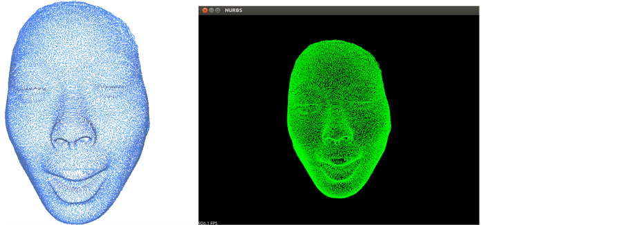
Figure 2. Input data and visualization window.
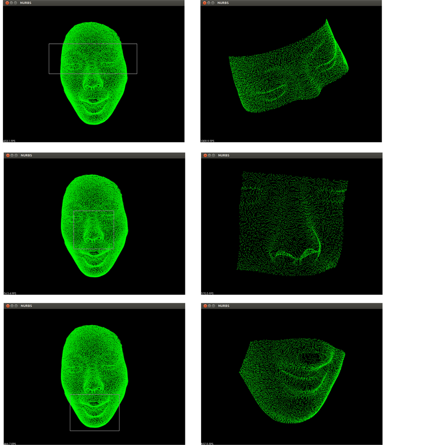
Figure 3. Selection process.

Figure 4. NURBS reconstruction from original data.

Figure 5. NURBS reconstructions from selections.
6. Conclusions and Future Work
This paper presented a new methodology for surface reconstruction through NURBS parameterization developed to be included in a coming version of InVesalius software. The methodology extracts a point cloud stored in PLY or STL files and reconstructs a NURBS surface from the entire data set or from a specific region of interest, exporting the result to a STEP file, such that the user is able to reopen and edit the surface reconstructed in any CAD software.
As seen in Figure 4 and Figure 5, the borders of the NURBS surfaces extrapolate those of the point clouds. Therefore, as future work, we intend to improve the algorithm behind the methodology, so both borders coincide or, at least, are as close as possible, thus enhancing the verisimilitude between the reconstructions and the original data.
Another direction for future work is to apply the developed methodology to the face recognition problem. 2D face recognition is a widely investigated topic, in contraposition to the ones that deal with 3D images. Furthermore, the tridimensional case, through surface shape and texture information simultaneously during the procedure, avoids recognition problems inherent to the bidimensional one, such as those resulting from illumination or face pose changes [15] . Therefore, we plan to employ surfaces reconstructed via NURBS parameterization on tridimensional face recognition processes using the control points net as a unique descriptor for each face.
Acknowledgements
The authors are grateful to São Paulo Research Foundation (FAPESP), Coordination for the Improvement of Higher Education Personnel (CAPES) and National Council for Scientific and Technological Development (CNPq) for their financial support.
Cite this paper
DaltonFazanaro,PauloAmorim,ThiagoMoraes,JorgeSilva,HelioPedrini, (2016) NURBS Parameterization for Medical Surface Reconstruction. Applied Mathematics,07,137-144. doi: 10.4236/am.2016.72013
References
- 1. Moraes, T.F., Amorim, P.H.J., Azevedo, F.S. and Silva. J.V.L. (2011) InVesalius—An Open-Source Imaging Application. In: Tavares, J.M.R.S. and Natal Jorge, R.M., Eds., Computational Vision and Medical Image Processing: VipIMAGE, CRC Press, Boca Raton, 405-408.
- 2. Schroeder, W., Martin, K. and Lorensen, B. (2006) The Visualization Toolkit: An Object-Oriented Approach to 3D Graphics. 4th Edition, Kitware, New York.
- 3. Lorensen, W. and Cline, H. (1987) Marching Cubes: A High Resolution 3D Surface Construction Algorithm. Computer Graphics, 21, 163-169.
http://dx.doi.org/10.1145/37402.37422 - 4. Roth, S. (1982) Ray Casting for Modeling Solids. Computer Graphics and Image Processing, 18, 109-144.
http://dx.doi.org/10.1016/0146-664X(82)90169-1 - 5. Piegl, L. (1991) On NURBS: A Survey. IEEE Computer Graphics and Applications, 11, 55-71.
http://dx.doi.org/10.1109/38.67702 - 6. Piegl, L. and Tiller, W. (1997) The NURBS Book. Springer-Verlag, New York.
http://dx.doi.org/10.1007/978-3-642-59223-2 - 7. Farin, G. (2002) A History of Curves and Surfaces in CAGD. In: Farin, G., Hoschek, J., Kim, M.-S., Hoschek, J. and Kim, M.-S., Eds., Handbook of Computer Aided Geometric Design, North Holland, 1-21.
http://dx.doi.org/10.1016/B978-044451104-1/50002-2 - 8. Farin, G. (2002) Curves and Surfaces for CAGD: A Practical Guide. Morgan Kaufmann, Burlington.
- 9. ISO 10303-21:2002 (2015) Industrial Automation Systems and Integration—Product Data Representation and Exchange—Part 21: Implementation Methods: Clear Text Encoding of the Exchange Structure.
- 10. ISO 10303-242:2014 (2015) Industrial Automation Systems and Integration—Product Data Representation and Exchange— Part 242: Application Protocol: Managed Model-Based 3D Engineering.
- 11. Rusu, R.B. and Cousins, S. (2011) 3D Is Here: Point Cloud Library (PCL). IEEE International Conference on Robotics and Automation, Shanghai, 9-13 May 2011, 1-4.
http://dx.doi.org/10.1109/icra.2011.5980567 - 12. Jolliffe, I.T. (2002) Principal Component Analysis. Springer-Verlag, New York.
- 13. Open CASCADE (2015).
http://www.opencascade.com/ - 14. Rhinoceros (2015). https://www.rhino3d.com/
- 15. Gkberk, B., Salah, A., Alyz, N. and Akarun, L. (2009) 3D Face Recognition: Technology and Applications. In: Tistarelli, M., Li, S.Z. and Chellappa, R., Eds., Handbook of Remote Biometrics, Springer, London, 217-246.
http://dx.doi.org/10.1007/978-1-84882-385-3_9