Wireless Engineering and Technology
Vol.2 No.4(2011), Article ID:8150,5 pages DOI:10.4236/wet.2011.24032
A Novel Ultra-Wideband Monopole Antenna with Band-Stop Characteristic
![]()
Department of Electronics and Communication Engineering, Urmia University, Urmia, Iran.
Email: hadijlk@gmail.com
Received July 28th, 2011; revised August 22nd, 2011; accepted September 13th, 2011.
Keywords: Band-Notched Antennas, Band Rejection Antennas, Planar Antennas, Ultra Wideband (UWB)
ABSTRACT
In this letter, a simple monopole antenna with variable band-notched characteristic for ultra wide band (UWB) function is proposed. Two L-shaped quarter-waveguide resonators coupled to the ground plane with two shorting tracks at the sides of the antenna are used to generate stop-band performance around 5.5 GHz (WLAN). The proposed antenna is fabricated on the substrate FR4 (relative permittivity of 4.7) and has a compact size of 16 × 28.5 × 1.6 mm. The designed antenna has a good impedance matching in 3.1 - 11.4 GHz frequency range with VSWR < 2, except the band 5- 5.85 GHz.
1. Introduction
Ultrawideband (UWB) communication systems have received great attention in the wireless world due to their merits such as high data rate, small emission power and low cost for short range access and remote sensing applications. However, interference between the existing narrow band wireless systems and UWB systems has been a concern due to the inherently ultra-wide operating frequency range for UWB communication. For instance, Wireless Local Area Network (WLAN) is operated at the frequencies of 2.4 GHz (2400 - 2484 MHz), 5.2 GHz (5150 - 5350 MHz), and 5.8 GHz (5725 - 5825 MHz). To overcome this problem, various UWB antennas with a band-notched function have been developed not only to mitigate the potential interference but also to remove the requirement of an extra bandstop filter in the system [1,2].
The common method to achieve the band-notched function is incorporating slots into the antenna’s main radiator, such as a U-shaped slot [2,3], a V-shaped slot [4], an arc-shaped slot [5], etc., generally half-wavelength resonator structures. In [6,7] it is shown that parasitic strips also can be used to produce the desired band-rejection at a particular frequency. Another way to obtain frequency notches is using simple open-end slits, which are usually quarter-wavelength long [7,8]. In [9] and [10] ring resonators are employed in order to realize the band-notched function. As it is shown in [11] a frequency notch can also be achieved by embedding a pair of T-shaped stubs inside an elliptical slot cut. It is demonstrated in [8] by inserting simple slits in antenna ground plane, a band-notched function can also be achieved.
In this letter, a novel planar UWB monopole antenna with variable frequency band-notch function is proposed. The present technique for creating filtering function has not yet been studied in the previous proposed antennas. The notched band, covering the 5 - 5.85 GHz WLAN band, is provided by a pair of L-shaped strips on the ground plane connected to the main radiation patch from the sides of the antenna using two strips.
The paper is organized as follows. Section 2 gives a brief description of the antenna configuration. Section 3 presents the proposed antenna design method and results of simulation using Ansoft HFSS. Section 4 reports on experimental results and Section 5 concludes the findings of this paper.
2. Antenna Configuration
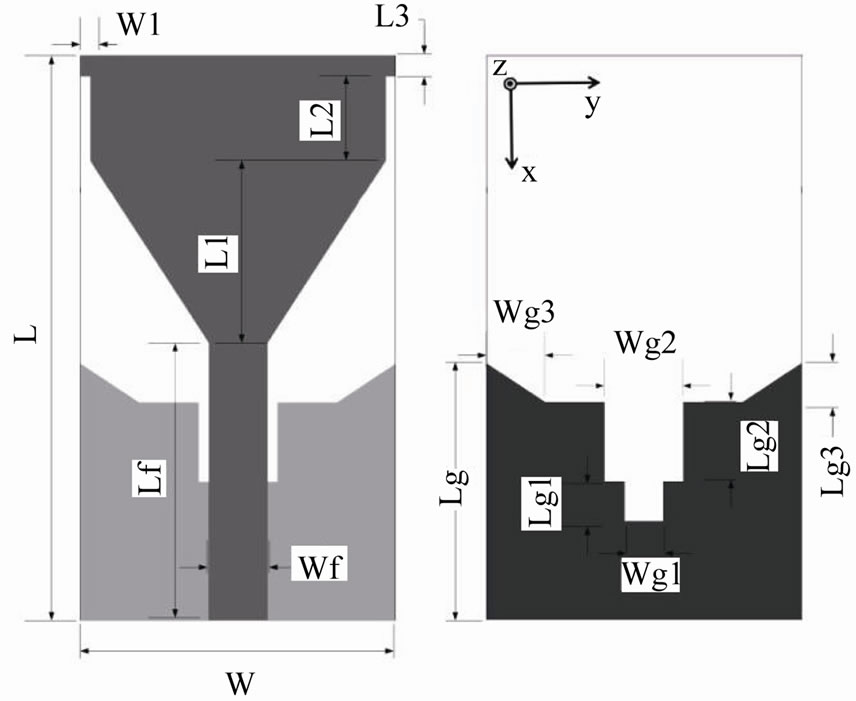
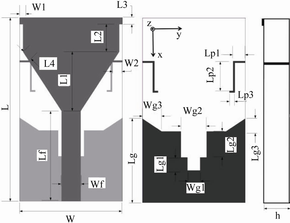
The base configuration of the antenna is refers to [12] but some changes has been applied on the parameters of the antenna, such as the gap size, total antenna size and the main radiation patch parameters. Figure 1 shows the geometry of the proposed antenna without band rejection. The antenna is printed on FR4 substrate with a thickness of 1.6 mm, a relative dielectric constant of 4.7, a tangen-
 (a) (b)
Figure 1. Proposed antenna configuration without bandnotch (a) top view (b) bottom view. L = 28.5 mm, W = 16 mm, Wf = 3 mm, Lf = 14 mm, L1 = 9.23, L2 = 4.27 mm, L3 = 1 mm, W1 = 0.5 mm, Lg = 13 mm, Lg1 = 2 mm, Lg2 = 4 mm, Lg3 = 2, Wg1 = 2 mm, Wg2 = 4 mm, Wg3 = 3 mm.
al loss of 0.02, a width W of 16 mm and a length L of 28.5 mm. The radiation patch has the shape of an inverted trapezoid but the length of the smaller parallel side is exactly equal to the width of the feed-line. This forms a smooth transition between the feed-line and the patch so the overall impedance matching is enhanced [12].The ground of this antenna plays an important role to obtain the good impedance matching from 3.1 GHz to 11.4 GHz. In this paper, two-step staircase notch with the total length of 6 mm is embedded in the truncated ground plane to improve the matching at lower frequency.
The notch creates a capacitive load that neutralizes the inductive nature of the patch [13]. Therefore, the width of the notch is very important and it is capable of improving impedance matching and it affects the capacitance value. The 50 Ohm feed line is terminated with a standard SMA connector to facilitate the measurement and connection with other standard microwave modules.
3. Antenna Design
In this section, the antenna covering the UWB band is first described. Then the new band notched structure is investigated. The effects of changing the geometric parameters of the proposed antenna on impedance matching and bandwidth are discussed. The proposed antenna structure is simulated using the Ansoft High Frequency Structure Simulator (HFSS) software.
3.1. UWB Antenna
The UWB antenna design features a gap (slot) between the radiation patch and the ground plane which introduces a coupling capacitance and plays an important role in obtaining UWB behavior. The size of the gap opening defines the impedance matching [14]. We have tapered the patch to get a smooth transition between the feed-line and the patch, and also we add two small triangles at the upper side of the ground plane to maintain the gap steady [12]. Figure 2 shows the simulated VSWR of the antenna without bandnotched function.
3.2. The Band Rejection Function for WLAN Band
The UWB system, operating between 3.1 - 11.4 GHz causes interference to the existing wireless communication systems, for example the WLAN operating in 5.15 - 5.85 GHz. The band rejection filter employed in UWB RF front-ends avoids the interference but gives complications to the UWB system. To overcome this difficulty, UWB antenna with a band rejected characteristic is required.
The band rejection function of the proposed antenna is achieved by printing two small L-shaped strips on the bottom side of the substrate and properly tuning the dimensions of the strips to determine the center frequency and bandwidth of the rejected band. The open circuited L-shaped strips introduced on the bottom side of the substrate are shunt connected to the main radiation patch from the sides of the antenna through two silver strips. The L-shaped strips act as resonator and introduce capacitive coupling to offer series resonance band stop function. Since the resonator has an impedance zero at its resonant frequency. The main line is effectively shorted at fr and thus no power is delivered to the radiation patch. It is to be noted that capacitive coupled transmission line inductor is less than quarter wavelength at the resonant frequency [14]. Figure 3 shows the Proposed bandnotched antenna configuration.
To estimate the center frequency at which the rejected bands are achieved, one may use the following formulas:
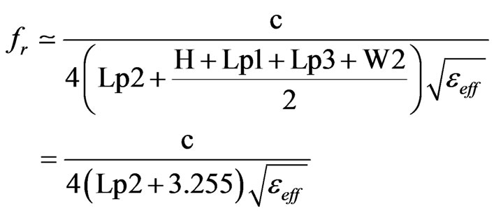
where 
 is the center frequency of the rejected band. We have a clear method for controlling the center frequency and bandwidth of the notch. Increasing the length of the L-shaped strips (increasing Lp2) has the effect of decreasing the center frequency and increasing the bandwidth. Also decreasing the distance of the Lshaped strips from ground plane (increasing L4) has the same
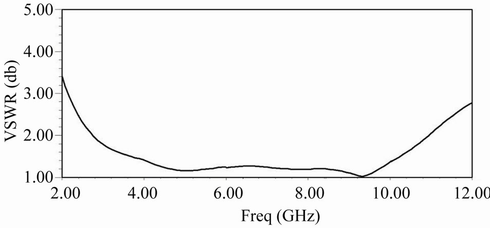
Figure 2. Simulated VSWR of the antenna without bandnotched function.
 (a) (b) (c)
Figure 3. Proposed band-notched antenna configuration (a) top view (b) bottom view (c) side view. L = 28.5 mm, W = 16 mm, Wf = 3 mm, Lf = 14mm, L1 = 9.23, L2 = 4.27 mm, L3 = 1 mm, W1 = 0.5 mm, W2 = 1.56, L4 = 1.59, Wp = 0.3, Lg = 13 mm, Lg1 = 2 mm, Lg2 = 4mm, Lg3 = 2, Wg1 = 2 mm, Wg2 = 4 mm, Wg3 = 3 mm, h = 1.6, Lp1 = 1.9, Lp2 = 4.6, Lp3 = 0.85.
effects. Figure 4 shows the simulated VSWR for various values of L4 for the band-notched antenna with other parameters fixed at the values shown in Figure 3. It is seen that, decreasing L4 leads to the rise of center frequency and it leads to the rise of bandwidth of the stopband by decreasing the lower frequency.
Figure 5 shows the variation of simulated VSWR with different values of Lp2. It indicates that the result of increasing Lp2 is decreasing the center frequency of the stopband and rising the VSWR and bandwidth value.
In this study, The center frequency of the stopband is varied by adjusting the length of Lp2, L4 and Lp3. Therefore, following (1) and fine adjusting from experiments for the desired center frequency of the rejection at 5.5 GHz, the total lengths of the folded strips are found to be 8.91 mm. Figure 6 shows the gain of the realized antenna from 2 - 12 GHz. The Figure indicates that the proposed antenna has reasonably good gain over the
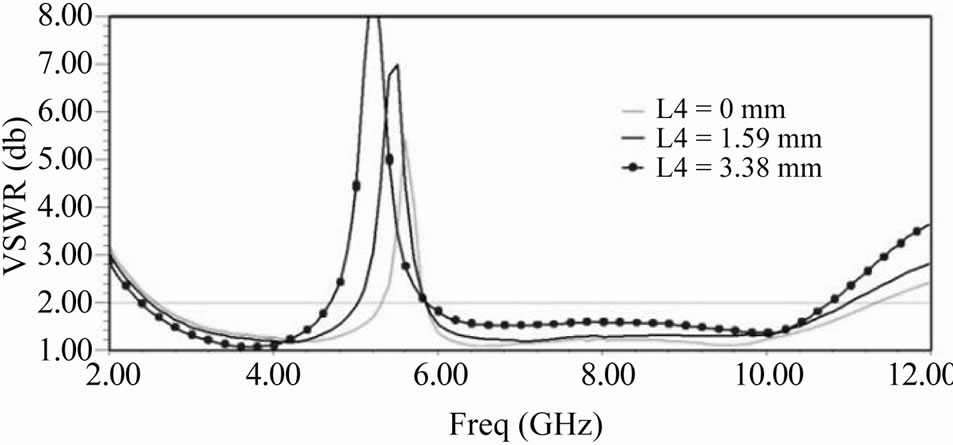
Figure 4. Simulated VSWR characteristics of the proposed antenna with different values of L4 and Lp2 = 4.6 mm.
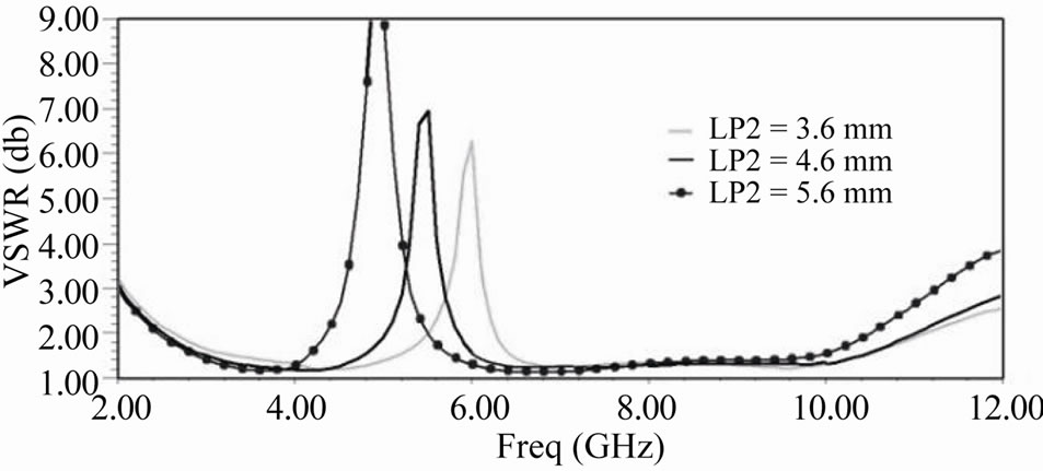
Figure 5. Simulated VSWR characteristics of the proposed antenna with different values of Lp2 and L4 = 1.59 mm.
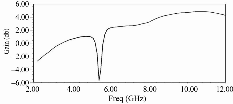
Figure 6. Gain of proposed antenna.
band of frequencies except for the notched band that we can observe an attenuate of the gain at this band. It means that the antenna does not radiate at the stop band.
Figure 7 and Figure 8 show H-plane and E-plane radiation patterns of the proposed antenna at different frequencies which depict antenna’s omnidirectional pattern and copolarization and crosspolarization level over wide range of frequency.
4. Measurement Results
The proposed band-notched UWB antenna was fabricated and fed by a 50 Ω SMA connector.
The measured and simulated reflection coefficient and VSWR of the proposed antenna from 2 - 12 GHz is shown in Figure 9 and Figure 10. We can see that the notched band is moved to upper frequency band in comparison to designed notched band. This difference is may be due to the error of realization process or due to the
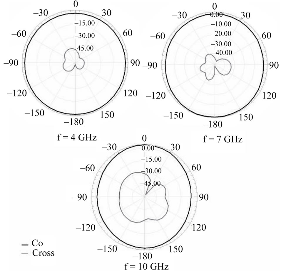
Figure 7. Radiation pattern of H plane at different frequencies.
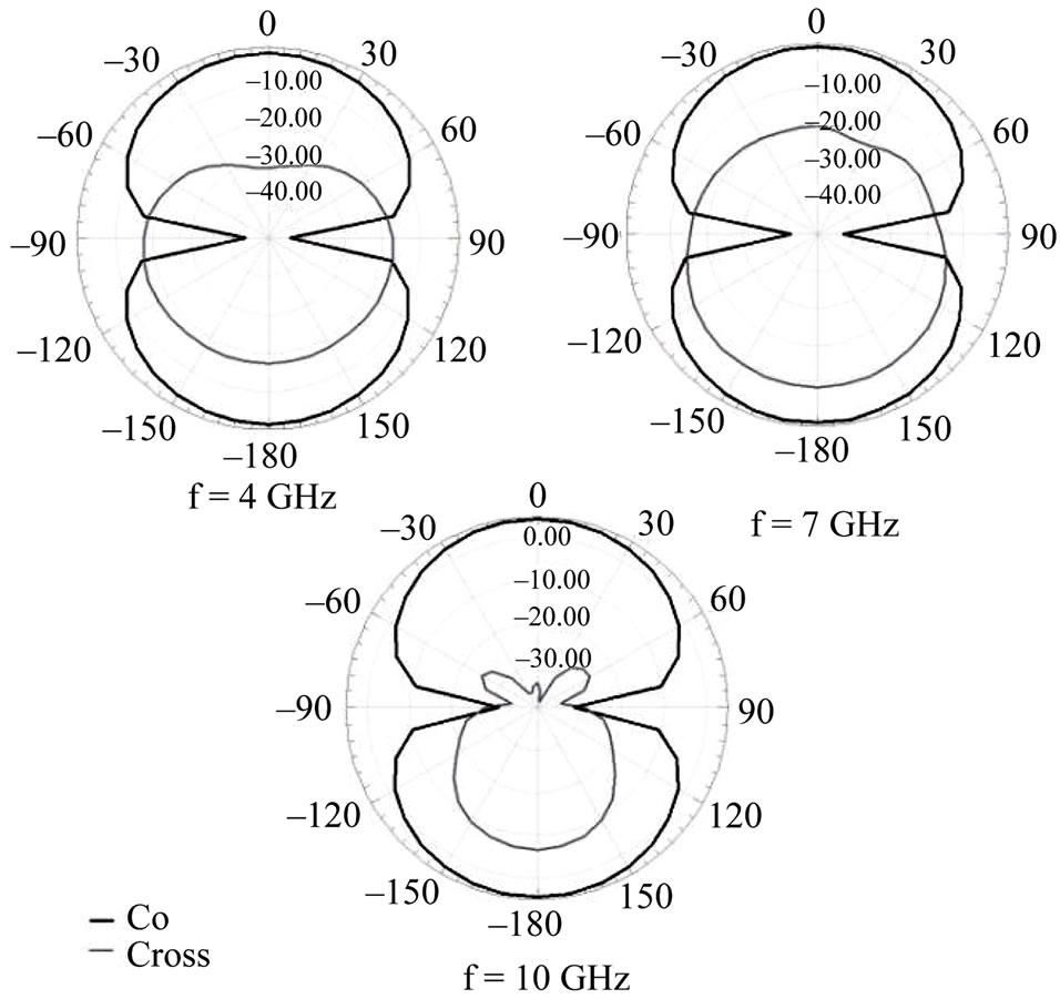
Figure 8. Radiation pattern of E plane at different frequencies.
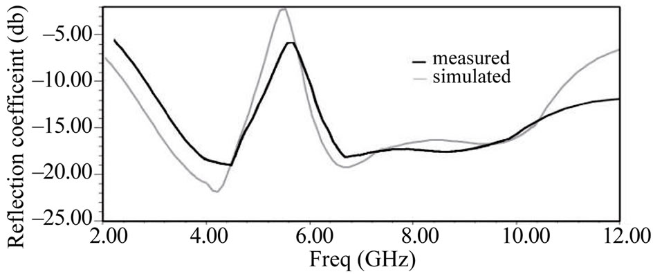
Figure 9. Measured and simulated reflection coefficient of the proposed antenna.
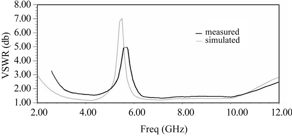
Figure 10. Measured and simulated VSWR of the proposed antenna.
tolerance of the substrate characteristics.
Both simulated and measured results suggest that the proposed antenna is suitable for UWB communication applications and at the same time dispenses the interference with WLAN systems.
5. Conclusions
The proposed band-notched Ultrawideband antenna exhibits broad bandwidth and good radiation performance. The radiation patterns of the antenna are almost stable in the entire band of operation. The antenna is compact and simple to fabricate. The overall antenna size is 28.5 mm × 16 mm × 1.6 mm.
6. Acknowledgements
The authors are thankful to the Antenna Lab of the Khaje Nasir Toosi University of Technology (Tehran, Iran) where the proposed antenna has been tested.
REFERENCES
- Y. D. Dong, W. Hong, Z. Q. Kuai and J. Y. Zhou, “Band-Notched Ultra-Wideband Antenna Designed and Optimized by Current Distribution Analysis,” Proceedings of the International Conference on Microwave and Millimeter Wave Technology, Nanjing, 2008, pp. 1062- 1065.
- W. S. Lee, D. Z. Kim, K. J. Kim and J. W. Yu, “Wideband Planar Monopole Antennas with Dual Band-Notched Characteristics,” IEEE Transactions on Microwave Theory and Techniques, Vol. 54, No. 6, 2006, pp. 2800-2806. doi:10.1109/TMTT.2006.874895
- T. P. Vuong, A. Ghiotto, Y. Duroc and S. Tedjini, “Design and Characteristics of a Small U-Slotted Planar Antenna for IR-UWB,” Microwave and Optical Technology Letters, Vol. 49, No. 7, 2007, pp. 1727-1731. doi:10.1002/mop.22515
- Y. Kim and D. H. Kwon, “CPW-FED Planar Ultra Wideband Antenna Having a Frequency Band Notch Function,” Electronics Letters, Vol. 40, No. 7, 2004, pp. 403- 405. doi:10.1049/el:20040302
- A. M. Abbosh, M. E. Bialkowski, J. Mazierska and M. V. Jacob, “A Planar UWB Antenna with Signal Rejection Capability in the 4-6 GHz Band,” IEEE Microwave and Wireless Components Letters, Vol. 16, No. 5, 2006, pp. 278-280.
- K. H. Kim and S. O. Park, “Analysis of the Small BandRejected Antenna with the Parasitic Strip for UWB,” IEEE Transactions on Antennas and Propagation, Vol. 54, No. 6, 2006, pp. 1688-1692. doi:10.1109/TAP.2006.875911
- Y. C. Lin and K. J. Hung, “Compact Ultrawideband Rectangular Aperture Antenna and Band-Notched Designs,” IEEE Transactions on Antennas and Propagation, Vol. 54, No. 11, 2006, pp. 3075-3081. doi:10.1109/TAP.2006.883982
- J. Jung, H. Lee and Y. Lim, “Compact Band-Notched Ultra-Wideband Antenna,” Electronics Letters, Vol. 44, No. 6, 2008, pp. 391-392. doi:10.1049/el:20083436
- J. Ding, Z. Lin, Z. Ying and S. He, “A Compact UltraWideband Slot Antenna with Multiple Notch Frequency Bands,” Microwave and Optical Technology Letters, Vol. 49, No. 12, 2007, pp. 3056-3060. doi:10.1002/mop.22892
- W. J. Lui, C. H. Cheng and H. B. Zhu, “Improved frequency Notched Ultrawideband Slot Antenna Using Square Ring Resonator,” IEEE Transactions on Antennas and Propagation, Vol. 55, No. 9, 2007, pp. 2445-2450.
- C. Y. Hong, C. W. Ling, I. Y. Yarn and S. J. Chung, “Design of a Planar Ultrawideband Antenna with a BandNotch Structure,” IEEE Transactions on Antennas and Propagation, Vol. 55, No. 12, 2007, pp. 3391-3397.
- N. D. Thong and V. V. Yem, “Combining Two Methods to Enhance Band-Notch Characteristic of Ultra Wide Band Antenna,” International Conference on Advanced Technologies for Communications, Hai Phong, 2009, pp. 206- 210.
- A. A. Eldek, “Numerical Analysis of a Small Ultra Wideband Microstrip-Fed Tap Monopole Antenna,” Progress In Electromagnetics Research, Vol. 65, 2006, pp. 59-69.
- K. G. Thomas and M. Sreenivasan, “A Simple Ultrawideband Planar Rectangular Printed Antenna With Band Dispensation,” IEEE Transactions on Antennas and Propagation, Vol. 58, No. 1, 2010, pp. 27-34.