Wireless Engineering and Technology
Vol.1 No.2(2010), Article ID:3027,5 pages DOI:10.4236/wet.2010.12010
Design of Aperture Coupled Microstrip Antenna Using Radial Basis Function Networks
![]()
1Department of Electronics and communication, Sikkim Manipal Institute of Technology, Majitar, India; 2Department of Electronics and Communication Engineering, Birla Institute of Technology, Mesra, India.
Email: contact_tanushree@rediffmail.com, ngupta@bitmesra.ac.in
Received August 15th, 2010; revised September 6th, 2010; accepted September 19th, 2010.
Keywords: Artificial Neural Network, RBF Nets, ACMSA
ABSTRACT
This paper, two Artificial Neural Network (ANN) models using radial basis function (RBF) nets are developed for the design of Aperture Coupled Microstrip Antennas (ACMSA) for different number of design parameters. The effect of increasing the number of design parameters on the ANN model is also discussed in this work. The performances of the models when compared are found that on decreasing the number of design parameters, accuracy of the model is increased. The results given by the prepared models are comparable with the results of the IE3D software. So, these models are accurate enough to measure the design parameters of ACMSAs. Thus the neural network approach eliminates the long time consuming process of finding various designing parameters using costly software packages.
1. Introduction
The artificial neural network can be referred to as an artificial human brain which processes data after proper training. Three basic aspects of a neuronal model are [1- 2]:
• It consists of a large number of processing elements like neurons and nodes
• Each nodes connect to a large number of other neurons and
• The functionality of the network is determined by modifying the strengths of the connection during the learning phase.
Ability, adaptive capability and ease of implementation have made ANN a popular tool for many design problems in today’s communication world. These networks directly give almost accurate result eliminating the various time consuming complex computations required for different works. In the present scenario, the neural network models are used extensively for wireless communication engineering, which eliminates the complex and time consuming mathematical procedures of designing antennas, like Method of Moments (MOM) [4-6].
In recent years, Wide band and Ultra wide band (UWB) technology have experienced many significant developments. Printed antennas play a very important role in this area because of their simple structure, ease of construction, low cost, conformal to planar, low profile, reproducibility and ease of integration with solid state devices [3]. However, the analysis of printed antennas is complex and exhaustive. To optimize the antenna efficiency for transmitting and receiving modes, the patch impedance should match with the feed hence it becomes very necessary to optimize the feed position. Moreover, the dimensions of antenna along with its feed line and dielectric of the substrate are other parameters which are to be optimized for antenna to operate in a desired resonant frequency or frequency band in case wide band and UWB operation [7-11]. Determination of these parameters is tedious, cumbersome and time consuming process.
In this proposed work, due to the high demand of wide band antennas in wireless communication, ACMSA’s design problems are taken under consideration. The error percentage in the first ANN model which is developed using RBF nets to give nine design parameters of the ACMSA is quite high while the time consumed by it is very low when it is compared with the one developed using Back propagation algorithm [12]. Since ACMSA is commonly used in wide band application, the relative error given by the ANN model developed using Radial Basis Function (RBF) is acceptable as the minimum frequency in the operating frequency band have a large space to resonate within the band. Still a low error percentage from the ANN models is always desirable, hence the second RBF-ANN model is developed to give only two design parameters of an ACMSA keeping other parameters fixed at some predetermined value. Both the models can be used to design an ACMSA for a desired minimum frequency in the frequency band ranging from 1.5 GHz to 8.9 GHz.
2. Antenna Design
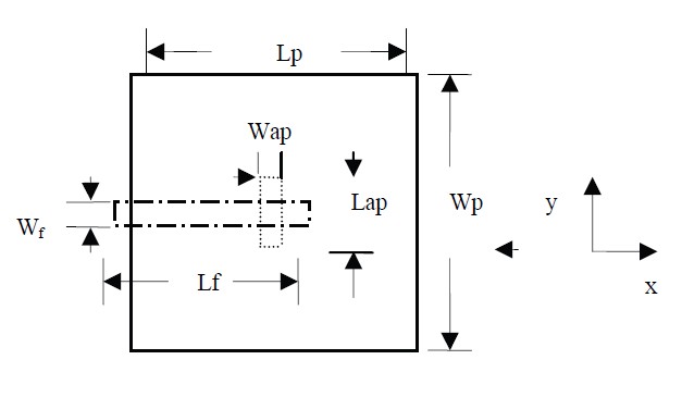
The geometry and the design parameters under consideration of an ACMSA are shown in Figure 1 and Figure 2, respectively. It consists of two substrates separated by a ground plane. The top substrate (era) contains the radiating element, and the bottom substrate (erb) contains the microstrip feed line. A small aperture is cut in the ground plane to allow coupling from open circuited microstrip feedline to the radiating patch. The parameters on which resonant frequency of the antenna depends upon are shape and dimensions of the radiating element, dimensions of the ground plane, shape and size of the aperture, dimensions of feedline, position of feedline and the dielectric constants of the two substrates [13-18].
An ACMSA can be designed for different frequencies using FR 4 sheet because of its easy availability. The shape of radiating element and aperture are chosen to be rectangular. The output parameters determined during the design of an antenna are:
(a) Dimensions of ground plane (Lg, Wg)
(b) Dimensions of aperture (Lap, Wap)
(c) Dimensions of radiating element (Lp, Wp)
(d) Dimensions of feed (Lf, Wf)
(e) Feed position (X, Y = 0)

Figure 1. Geometry of an ACMSA.

Figure 2. Design parameters in an ACMSA.
3. Development of ANN Model
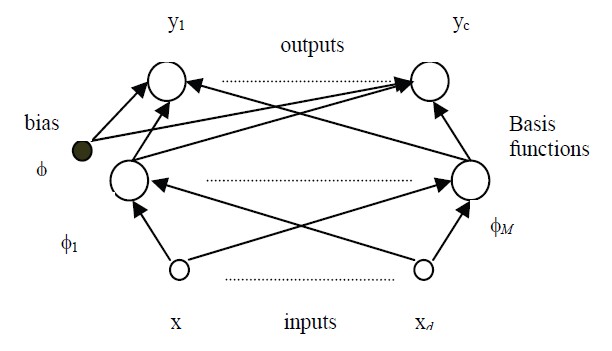
The construction of RBF network, in its most basic form, involves three layers with entirely different roles. The input layer is made up of source nodes (sensory units) that connect the network to its environment. The second layer, the only hidden layer in the network applies a nonlinear transformation from the input space to the hidden space. In most applications the hidden space is of high dimensionality. The output layer is linear, supplying the response of the network to the activation pattern applied to the input layer. A RBF net architecture is given in Figure 3.
Radial Basis function networks are substantially faster than the methods used to train multi-layer perceptron networks. This follows from the interpretations which can be given to the internal representation formed by the hidden units, and leads to a two stage training procedure. In the first stage, the parameters governing the basis functions (corresponding to hidden units) are determined using relatively fast, unsupervised methods, in which it uses only input data and not the target data. The second stage of training then involves the determination of the final-layer weights, which requires the solution of a linear problem, and which is therefore also fast.
The trained neural network provides a special approximation where the exact results of the numerical

Figure 3. A RBF network architecture.
analysis, which are hidden in the training patterns, are used for neural computation and give us directly all the required designing parameter of an antenna for a desired frequency. That way, a computationally modest neural network model can replace a numerical analysis for parameters differing from training patterns.
4. Results and Discussions
In this proposed work, first an ANN model for aperture coupled microstrip antenna, considering nine design parameters is developed using RBF network. The simulated values which are trained for the model development and the antenna configurations are obtained from the IE3D software, which is a commercial simulator based on the moment of methods. The number of training data is increased by the method of interpolation which is quite reliable because interpolation technique is applied on the graph that is obtained from the simulated data. The network is trained with radial basis function network, whose performance goal was taken as 0.0001% and spread constant is 400. For 831 input/output training samples, the network requires only 4 minutes for training, and Relative error (percentage error) is found to lie within 20% to 60%. The time taken to develop the same model using RBF network is very less while error% is quite high than that found with the model which was prepared using BPA network [7]. Relative error is calculated using the formula as follows:
Relative Error = [(Simulated Value – ANN Value)
/Simulated value] *100(1)
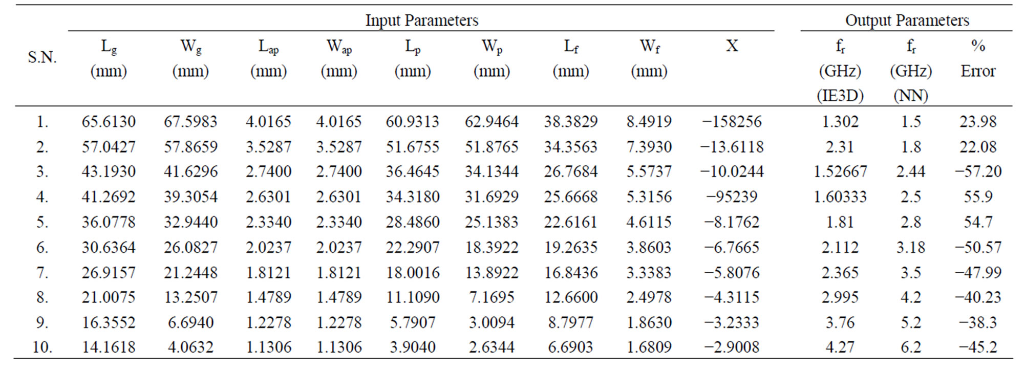
The network is tested for 10 random frequencies. Those input frequencies are compared with the resonant frequencies obtained from IE3D software for the corresponding output parameters given by the network. The results are tabulated in Table 1 for all the parameters, which also compare the simulated value with the one obtained from the ANN model.
From Table 1 one can estimate that the prepared network or model is good enough for determining the various design parameters of an ACMSA operating between 1.5 GHz and 8.9 GHz. The above mentioned characteristics of the ACMSA obtained from the ANN model are found to have high errors but due to the wide band property of ACMSA, the errors are still acceptable. The reason behind this high error is cumulative error caused by large number of design parameters taken under consideration. To reduce this, next an ANN model is developed considering only two design parameters.
Now, a RBF – ANN model for two design parameters is developed keeping the configuration of RBF net same as that developed for the design of ACMSA for nine design parameters. The developed RBF – ANN model for two design parameters of ACMSA is checked for 10 random frequencies. The design parameters given by this model when simulated using IE3D software gives the expected results and it is found that error % is reduced highly. Comparison of the minimum frequency in the frequency band obtained by simulated and the RBFANN model for two design parameters for ACMSA is tabulated in Table 2. The error % is found to lie between 0.2% and 10% and time taken to develop this model is just 10 seconds.
The time taken for the development of the ANN model using RBF nets is very less and this learning method is good for the development of such ANN model which is used to obtain less number of design parameters. If the design parameters are increased, error % increases which in turn affects the efficiency of the ANN model. For large number of design parameters, training should be

Table 1. Error measurement for the simulated fr from IE3D and the NN model using radial basis network for the design of ACMSA for nine design parameters.

Table 2. Error measurement for the simulated fr from IE3D and the NN model using RBF network for the design of ACMSA for 2design parameters.

Table 3. Comparison of mean error % and time taken by different ANN models, for the design of ACMSA.

Table 4. Comparison showing minimum frequency obtained from different methods.
done using back propagation algorithm. Table 3 shows the comparison of mean error % and time taken for the development of the different ANN models. Mean error % is calculated as given in Equation (2) and a comparison of the resonant frequencies obtained by ANN model, IE3D software and the prototype model when measured in vector network analyzer is shown in Table 4.
Mean = S |RelativeError|/10(2)
5. Conclusions
The trained networks are very useful as they give all the design parameters of the ACMSA for any desired resonant frequency. A distinct advantage of neural computation is that, after proper training, a neural network completely bypasses repeated use of complex iterative processes for new design presented to it. This work can be extended for various dielectric constants for different radiating patch.
REFERENCES
- S. Haykin, “Neural Networks - A Comprehensive Foundation,” Pearson Educartion Pte. Ltd., Singapore, 2004.
- S. N. Sivanandam, S. Sumathi and S. N. Deepa, “Introduction to Neural Networks using Matlab 6.0,” Tata McGraw-Hill, New Delhi, 2006.
- C. A. Balanis, “Antenna Theory Analysis and Design,” John Wiley & Sons, Inc., New York, 2005.
- R. K. Mishra and A. Patnaik, “Neural Network-Based CAD Model for the Design of Square Patch Antennas,” IEEE Ttransactions on Antennas and Propagation, Vol. 46, No. 12, December 1998, pp. 1890-1891.
- R. K. Mishra and A. Patnaik, “Neorospectral Computation for Complex Resonant Frequency of Microstrip Resonators,” IEEE Microwave and Guided Wave Letters, Vol. 9, No. 9, September 1999, pp. 351-353.
- A. Patnaik and R. K. Mishra, “ANN Techniques in Microwave Engineering,” IEEE Microwave Magazine, Vol. 4, No. 1, March 2003, pp. 55-60.
- Z. Wang, “Design of Low-SAR Antennas for Mobile Communications Devices,” Ph.D. Thesis, 2001.
- D. K. Cheng, “Field and Wave Electromagnetics,” 2nd Edition, Addison Wesley, Reading, 1989.
- E. Antonino-Daviu, M. Cabedo-Fabre’s, M. FerrandoBataller and A. Valero-Nogueira, “Wideband Double-Fed Planar Monopole Antennas,” Electronics Letters, Vol. 39 No. 23, November 2003, pp. 1635-1636.
- K.-L. Wong, C.-H. Wu and S.-W. (Stephen) Su, “Ultrawide-Band Square Planar Metal-Plate Monopole Antenna with a Trident - Shaped Feeding Strip,” IEEE Transactions on Antennas and Propagation, Vol. 53, No. 4, April 2005, pp. 1254-1261.
- J. Jung, W. Choi and J. Choi, “A Small Wideband Microstrip Fed Monopole Antenna,” IEEE Microwave and Wireless Components Letters, Vol. 15, No. 10, October 2005, p. 630.
- T. Bose and N. Gupta, “Neural Network Model for Aperture Coupled Microstrip Antennas,” Microwave Review, September 2008.
- T. K. Lo, C. O. Ho, Y. Hwang, E. K. W. Lam and B. Lee, “Miniature Aperture-Coupled Microstrip Antenna of Very High Permittivity,” Electronics Letters, Vol. 33, No. 17, January 1997, pp. 9-10.
- R. B. Waterhouse, S. D. Targonski and D. M. Kokotoff, “Design and Performance of Small Printed Antennas,” IEEE Transactions on Antennas and Propagation, Vol. 46, No. 12, 1998, pp. 1629-1633.
- M. A. Saed, “Efficient Method for Analysis and Design of Aperture Coupled Rectangular Microstrip Antenna,” IEEE Transactions on Antenna Propagation, Vol. AP-41, 1993, pp. 986-988.
- P. L. Sullivian and D. H. Schaubert, “Analysis of an Aperture Coupled Microstrip Antenna,” IEEE Transactions on Antenna propagation, Vol. AP-34, 1986, pp. 977-984.
- A. Ittipibbon, et al., “A Modal Expansion Method of Analysis and Measurement on Aperture-Coupled Microstrip Antennas,” IEEE Transactions on Antenna Propagation, Vol. Ap-39, 1991, pp. 1567-1574.
- V. Rathi, G. Kumar and K. P. Ray, “Improved Coupling for Aperture Coupled Microstrip Antennas,” IEEE Transactions on Antenna Propagation, Vol. AP-44, No. 8, 1996, pp. 1196-1198.

