Energy and Power Engineering
Vol.5 No.3(2013), Article ID:31123,6 pages DOI:10.4236/epe.2013.53020
Design Method Based on Normalized Functions for a Toroidal Inductor Applied to Power-Quality Evaluation*
Department of Electronics, National Polytechnic Institute, Mexico City, Mexico
Email: rbaca02006@yahoo.com.mx
Copyright © 2013 Roberto Baca. This is an open access article distributed under the Creative Commons Attribution License, which permits unrestricted use, distribution, and reproduction in any medium, provided the original work is properly cited.
Received February 20, 2013; revised March 22, 2013; accepted April 5, 2013
Keywords: Transfer Function; Equivalent Circuit; Normalized Parameters; Current-Signal Sensor; Harmonic Analysis
ABSTRACT
The design method for a low-cost toroidal inductor is proposed as an alternative to power-quality evaluation. The method is based on well-known tools by the engineers in which is presented the relationships that exist between equivalent circuit and transfer function of a toroidal inductor. The proposed design method has been explained with normalized functions based on physical parameters of a toroidal inductor. This work presents the main arguments of the suggested methodology and as demonstration of the design method as function of normalized parameters, is developed a current-signal sensor which has been validated in the laboratory by the EN-50160-2-2 standard to evaluate the power quality in home use loads.
1. Introduction
In electrical engineering a toroidal inductor is used to measure or monitor the electric currents of an AC power circuit as a function of the harmonic distortion [1,2]. A galvanically isolated current measurement is required, such that the advantages of lower losses nd measurement signals processed directly must be attained [3]. A toroidal inductor produces a reduced current accurately proporonal to the measured current. The toroidal inductor can be also commonly used for feedback control, and other applications [4].
The design method of toroidal inductors have been developed by a non iterative method, which introduce an equation for estimation of the core size required as function of the wanted inductance and the maximum values specified for induction and current [5]. Another method solution consists in modeling inductors along with the equivalent circuits, calculation of the leakage inductance, core material characteristics, and geometrical configuretion for the minimization of volume inductors in order to simplify the design procedure [3]. Nevertheless, the trend for the current monitoring is driven by cost reduction, an increased functionality, and limited weight/space in some applications [3,4].
This finally results in constantly increasing frequencies, which comes along with and increased bandwidth and poor stability.
Based on electric and magnetic properties, like saturation magnetization, and toroidal-core losses, here is proposed the possibility of application of the grain-oriented silicon-iron cores for current monitoring, because these can reduce phase error and improve its accuracy in measurements of AC current at low frequencies (50 - 60 Hz) [6,7]. A simple method for toroidal-inductor design at minimum losses is suggested to calculate several inductors accepting a broad tolerance of the core material features.
In general, the inductor design procedure described in literature makes use of numerous monograms, and the final result is achieved through several iterations. In special, toroidal inductors have been designed by several engineers with tedious methods [8-10]. For that reason, the lack of deeper understanding of the fundamental electromagnetic laws, it makes many engineers to consider the design of inductive components a difficult task.
The purpose here is to explain a design method based on well-known tools by engineers [11]; presenting in a simple and easy way the relationships that exists between equivalent circuit and transfer function of a toroidal inductor. The proposed work is developed to meet the following objectives:
1) To explain the relationship between equivalent circuit and magnetic parameters of a toroidal inductor;
2) To develop the method based on normalized parameters;
3) To demonstrate the method validation with a current-signal sensor and evaluate the EN-50160-2-2 standard as a function of single harmonic distortion (SHD) in home use loads [1].
2. Characteristics of the Toroidal Inductor
Like any other transformer, a toroidal inductor has a primary winding, a magnetic core, and a secondary winding. When is induced a voltage in the secondary winding circuit, the line wire (primary winding) is magnetically encircled by the toroidal core as shown in the schematic diagram of Figure 1. The toroidal geometry takes the following advantages of operation:
1) Improved response at over-current detection, because it has a high inductance and differential permeability [6].
2) The magnetic field induced by line wire is proportional to the rate of integrative change of voltage, as consequence its resistance of secondary winding should be r > 1 Ω [12,13].
3) Sensitivity can be improved when currents through primary winding (line wire) are smaller as a function of the size toroidal geometry [6,14].
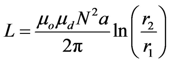
For any toroidal inductor, the core loss and magnetizing currents must be kept to a minimum [9]. Therefore, a toroidal geometry must be modeled by equations that describe its exact behavior [12] and their exact inductance with square cross section given by
 . (1)
. (1)
where μd is differential permeability of core, μo is permeability of free space, N is number of turns, r1 is inner radius, r2 is outer radius, and a the thickness of the toroidal core, respectively.
A better understanding for a toroidal inductor may be achieved when the input current, Iin is divided into the several currents [9,13]. Figure 2 shows their simplified equivalent circuit, where Xm is the magnetizing reactance, rs is the winding resistance, and Ro is the output load, respectively.
Only the line wire encircled by the toroid drives the magnetic field around the core and it then induces a voltage to the output load, Ro proportional to output current, Io. While, the magnetizing current, Im is the portion of input current, Iin dependent to hysteresis and current losses of the core.
Following analysis gets the normalized functions to the modeling of a toroidal inductor as a function of the normalized parameter α and physical parameters.
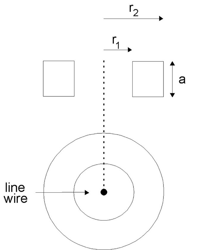
Figure 1. Schematic diagram of the toroidal geometry with square cross section.
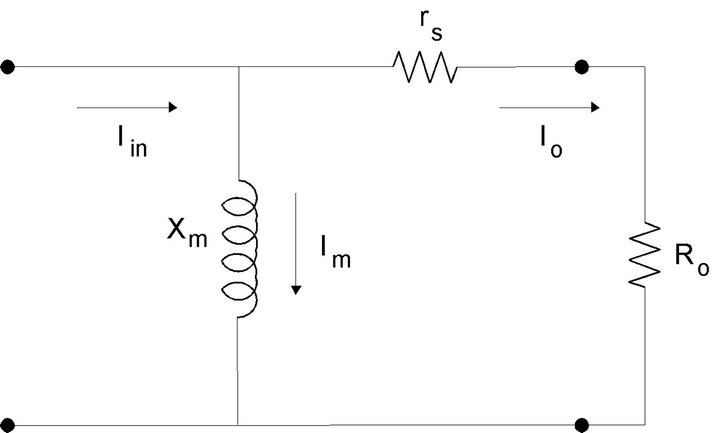
Figure 2. Simplified equivalent circuit for a toroidal inductor.
2.1. Transfer Function
A relationship between induced voltage, Vs and input current, Iin in a transfer function is resulting from Figure 2 and should be given by 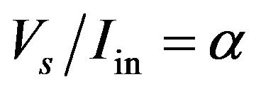 [11].
[11].
α determines the amount of induced voltage, Vs from the toroid per input current, Iin flowing through a line wire and establish the condition in which their behavior is equal to ideal inductance (without losses).
A transfer impedance, Zt can be related to α and obtained with the parallel circuit between (rs + Ro) and Xm. It can be solved as 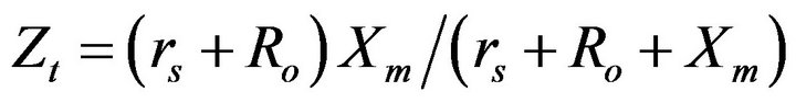 with Xm = sLm. At s = jω by substituting of magnetizing reactance, Xm the transfer impedance, Zt can be established by
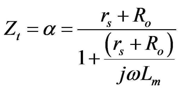 . (2)
. (2)
From Equation (2), cut-off frequency, ωc for a toroid by equating with zero and after equating the real and imaginary parts is corresponding to
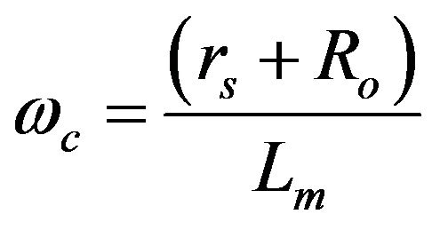 . (3)
. (3)
where Lm is the magnetizing inductance, and  is the equivalent resistance for the toroidal inductor [9].
2.2. Magnetizing Impedance
It is known that magnetization is a nonlinear phenomenon and different values of magnetizing reactance, Xm must be corresponding for each level of induced voltage through line wire, with input current, Iin. Nevertheless, a toroid inductor can be modeled by its magnetizing impedance, Zm, because the magnetizing current, Im is expand from line wire as magnetic field in order to excite the core [8,12].
An ideal transformer model can be related at magnetizing impedance, Zm without take into account copper and core losses [12]. From input impedance
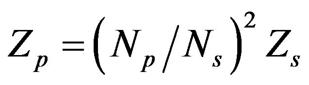 for ideal transformers [10], the toroid impedance with Np = 1 (primary winding) as a function of the voltages and currents of their windings can be defined by
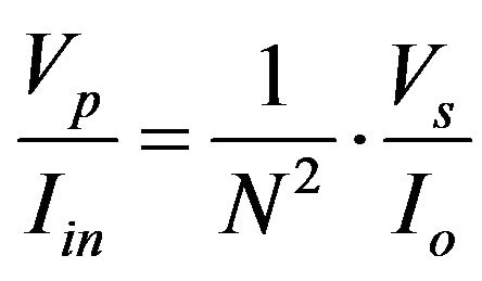 . (4)
. (4)
Multiplying both sides of Equation (4) by  is obtained the following relationship
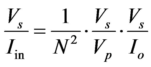 . (5)
. (5)
It is known that storage magnetic energy in the core is proportional to induced voltage, Vs and reflected on the output load, Ro [9,12]. Substituting  by N, and
  by α, the secondary impedance,
  is proportional to Zm as
 . (6)
. (6)
where N is the number of turns.
3. Design Method
In this section a design method based on the normalized parameter, α is presented. Equations (1)-(3), and (6) are driven according to the following arguments:
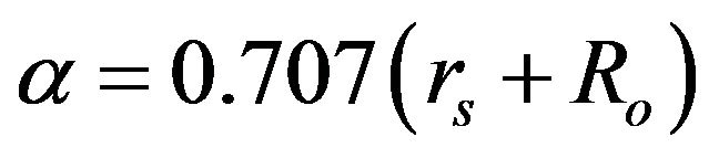
1) Substituting ωc in Equation (3) and at ωc = ω in Equation (2), the normalized parameter, α for a toroidal inductor is corresponding to
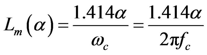
2) Substituting (rs + Ro) as 1.414 α in Equation (3), the magnetizing inductance, Lm(α) is calculated by
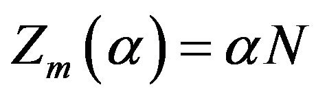
3) The magnetizing impedance, Zm for a toroid is expected from Equation (6) as
Simulations of the Proposed Method
The purpose of this subsection is to theoretically prove the performance of the proposed method by using the normalized functions from the last arguments and Equation (1), respectively. These equations are then solving by MATHEMATICA 5 program in the range of 0.2 < α < 1 which satisfy the condition r > 1 Ω (minimum losses). The results are shown in Table 1.
The useful parameters at minimum losses in Table 1 can be used as reference for any practical toroidal-inductor design through the following steps:
a) Should be chosen the core material of differential permeability according to application and calculate the number of turns, N from Equation (1).
b) Is calculated the magnetizing impedance, Zm(α) as a function of normalized parameter, 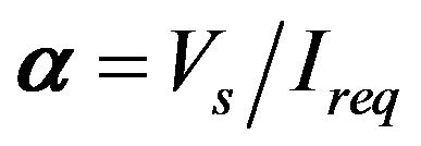 , which depend on required specifications.
c) Is calculated the required number of turns, Nreq for the required current, Ireq with the following simple equation
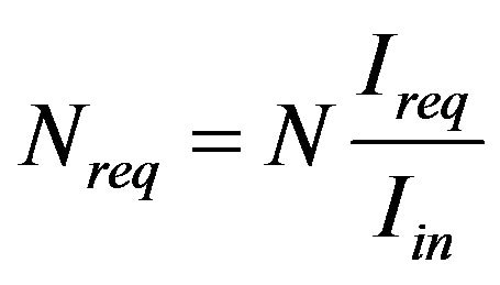 . (7)
. (7)
d) The output current, Io is defined as 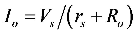 with
with 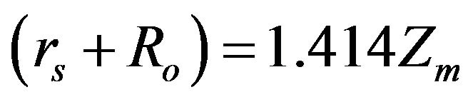 according to Equation (2) at ωc = ω. Therefore, the output current, Io can be evaluated as
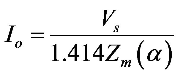 . (8)
. (8)
4. Power-Quality Evaluation
A current-signal sensor with the following specifications: Ireq = 5 A, and Vs = 1 V, which correspond to α = 0.2, was designed to monitoring of the line-current waveform in typical home use loads.
The design requires grain-oriented silicon-iron core of differential permeability (μd ~ 120) [6] to build the toroid
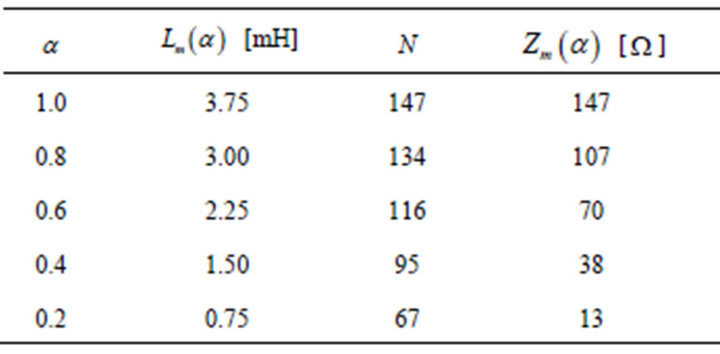
Table 1. Normalized parameters for toroidal inductors at minimum losses.
with a = 10 mm and r2 = 2 r1 conditions. The number of turns, N was obtained from Equation (1). From the normalized parameters of Table 1 was chosen the parameters which satisfy the α = 0.2 parameter. Using the Equations (7) and (8) is easy to find the requested number of turns Nreq and output current Io.
Table 2 lists the parameters for the current-signal sensor. The winding on square cross section toroid with a = 10 mm, r2 = 4 cm, and r1 = 1.8 cm was manufactured by a technician. Figure 3 shows the photo of the manufactured toroid. The wire area for the current Io is corresponding to AWG No. 31 [10,14].
Is known that harmonics are caused by non sinusoidal loads and affect the current waveform of line wires and this parameter must be satisfied by the limits set by EN-50160-2-2 standard as a function of single harmonic distortion (SHD) with smaller value of 8% [1].
Based on EN-50160-2-2 standard, both AC voltage and current on line wires are measured at different loads in order to demonstrate the behavior of the toroidal inductor previously designed. The line voltage is 125 V (60 Hz), and Ro = 100 Ω is connected in parallel with the toroid to complete the electric circuit of Figure 2.
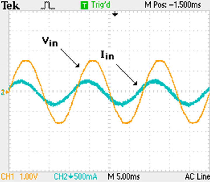
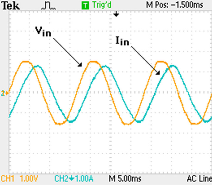
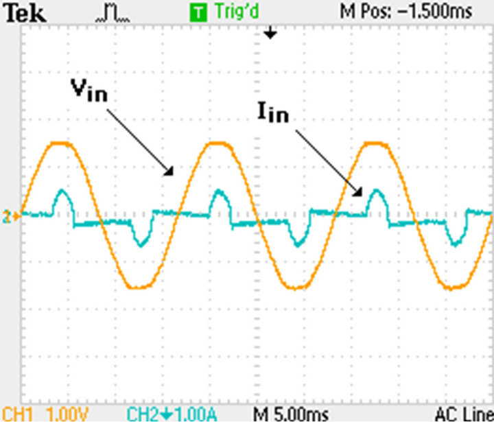
Figure 4(a) shows the line current and voltage waveforms on an incandescent lamp with Iin = 0.85 A. Figure 5(a) shows the line current and voltage waveforms on an AC electric motor of ½ HP with Iin = 3.40 A. Figure 6(a) shows the line current and voltage waveforms on a switching-mode load with Iin = 1.10 A.
Based on Fast Fourier Transform (FFT) function analysis [2,15], and using a digital storage oscilloscope (Tektronix, TDS1012C), the FFT spectrum of the line current harmonics at the same loads was measured in Figures 4(b), 5(b) and 6(b).
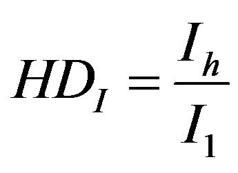
From the FFT spectrum corresponding to input current, the percentage of the harmonic currents to the fundamental current was evaluated. In the EN-50160-2-2 standard is suggested a harmonic analysis carried out by the following equation
 . (9)
. (9)
where I1 is fundamental current, Ih is harmonic currents with h as harmonic number.
Using the FFT spectrum was calculated the SHD percentage with Equation (9). Table 3 lists the corresponding values.
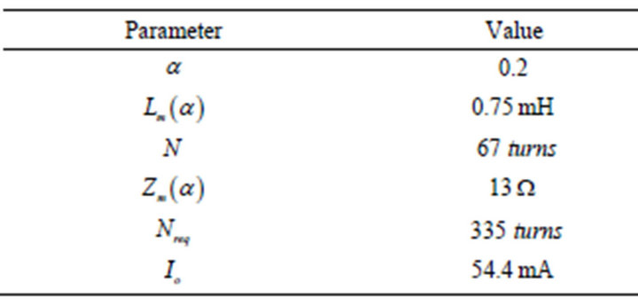
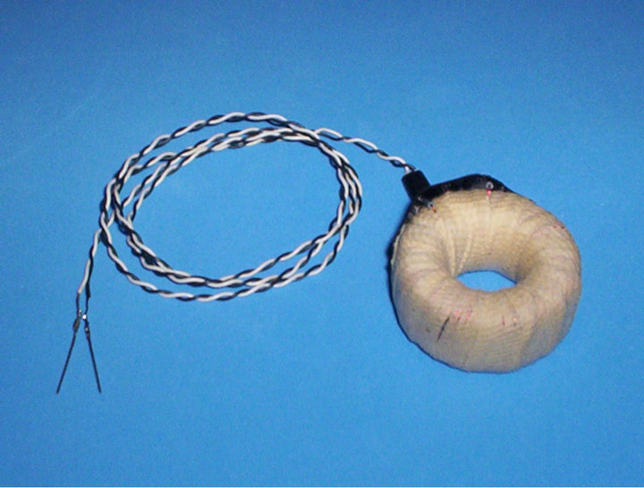
Figure 3. Photo of the toroid as current-signal sensor.
 (a)
(a)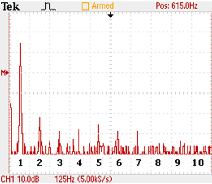 (b)
(b)
Figure 4. (a) Monitoring of the current and voltage waveforms, and (b) FFT spectrum of the current signal in the incandescent lamp.
 (a)
(a)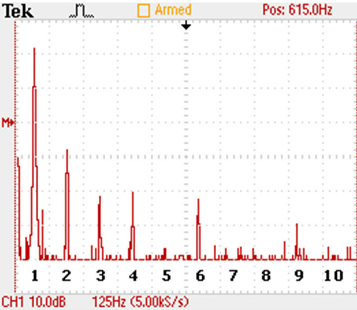 (b)
(b)
Figure 5. (a) Monitoring of the current and voltage waveforms, and (b) FFT spectrum of the current signal in the AC electric motor.
 (a)
(a)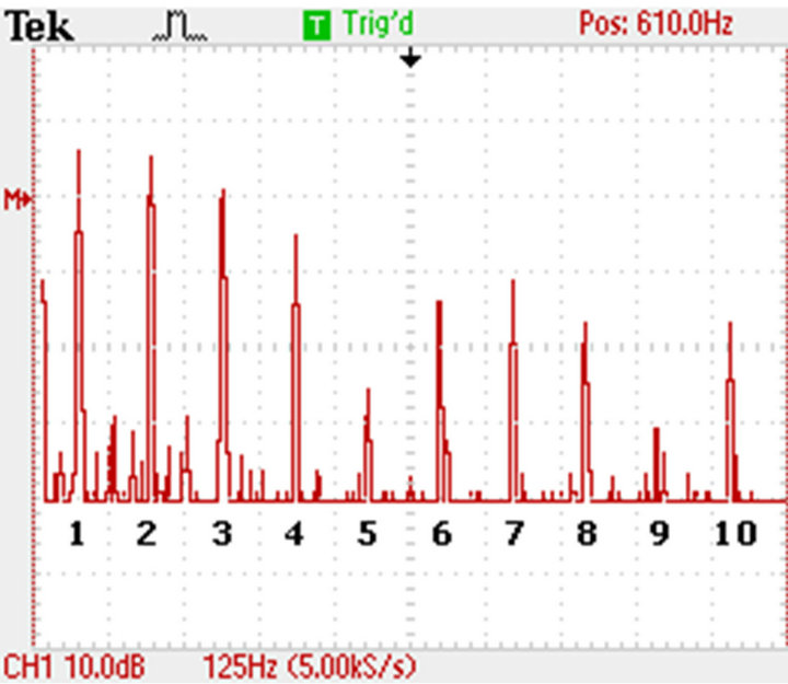 (b)
(b)
Figure 6. (a) Monitoring of the current and voltage waveforms, and (b) FFT spectrum of the current signal in the switchingmode load.
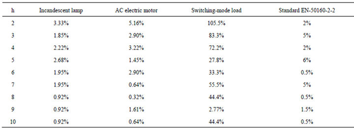
Table 3. Single HD values from FFT spectrum.
Both incandescent lamp and AC electric motor of 1/2 HP is exhibiting lower percentage in odd harmonics and higher percentage in even harmonics in comparison to EN-50160-2-2 standard. A switching-mode load is showing extremely higher percentage in both odd and even harmonics, because serious discontinuity of its current waveform was observed [16,17].
5. Conclusions
In this work a method of design based on normalized parameters for a low-cost toroidal inductor was proposed. Based on proposed method a current-signal sensor was designed to monitoring of the AC current waveforms.
Two normalized functions have been found. One is the magnetizing inductance, Lm(α), another is magnetizing impedance, Zm(α). These parameter leads to obtain in general an optimal design of any toroidal inductor as a function of α parameter.
A toroid was built with recycled grain-oriented silicon-iron foils. From the results was observed that the home use loads do not satisfy the EN-50160-2-2 standard which should be corrected in the future. Also, with some suggestions, the proposed method can be expanded to special design of toroidal inductors for other applications.
6. Acknowledgements
The author would like to acknowledge to the Mr. Antonio Luis Tino for its help with the manufacturing of the current-signal sensor.
REFERENCES
- EN-50160-2-2 Standard, “Voltage Characteristics of Electricity Supplied by Public Distribution Systems,” 2004.
- J. Z. Young, C. S. Yu and C. W. Liu, “A New Method for Power Signal Harmonic Analysis,” IEEE Transactions on Power Delivery, Vol. 20, No. 2, 2005, pp. 1245-1239.
- M. L. Heldwein, L. Dalessandro and J. W. Kolar, “The Three-Phase Common-Mode Inductor: Modeling and Design Issues,” IEEE Transactions on Industrial Electronics, Vol. 58, No. 8, 2011, pp. 3264-3274. doi:10.1109/TIE.2010.2089949
- M. Hartmann, J. Biela, H. Ertl and J. W. Kolar, “Wideband Current Transducer for Measuring AC Signals with Limited DC Offset,” IEEE Transactions on Power Electronics, Vol. 24, No. 7, 2009, pp. 1776-1787. doi:10.1109/TPEL.2009.2017263
- H. E. Tacca, “Ferrite Toroidal Inductor Design,” IEEE Latin America Transactions, Vol. 7, No. 6, 2009, pp. 630- 635. doi:10.1109/TLA.2009.5419359
- W. A. Geyger, “Nonlinear-Magnetic Control Devices, Basic Principles, Characteristics, and Applications,” McGrawHill Book Company, New Delhi, 1964.
- B. Kovan, F. León, D. Czarkowski, Z. Zabar and L. Birenbaum, “Mitigation of Inrush Currents in Network Transformers by Reducing the Residual Flux with Ultra-Low-Frequency Power Source,” IEEE Transactions on Power Delivery, Vol. 26, No. 3, 2011, pp. 1-8.
- R. Petkov, “Optimal Design of a High-Power, HighFrequency Transformer,” IEEE Transaction on Power Electronics, Vol. 11, No. 1, 1996, pp. 33-42. doi:10.1109/63.484414
- S. E. Zocholl and D. W. Smaha, “Current Transformer Concepts, “ Proceedings of the 46th AGTPR Conference, Atlanta, 29 April-1 May 1992, pp. 1-8.
- G. Chryssis, “High-Frequency Switching Power Supplies: Theory and Design,” McGraw-Hill, New York, 1989.
- A. S. Sedra and K. C. Smith, “Microelectronics Circuits,” Oxford University Press, New York, 1998.
- J. A. Edminister, “Theory and Problems of Electromagnetics, Shaum’s Outline Series,” United States of America, McGraw-Hill, New York, 1995.
- P. R. Wilson, J. N. Ross and A. D. Brown, “Modeling Frequency-Dependent Losses in Ferrite Cores,” IEEE Transactions on Magnetics, Vol. 40, No. 3, 2004, pp. 1537-1541. doi:10.1109/TMAG.2004.826910
- P. L. Dowell, “Effects of Eddy Currents in Transformer Windings,” Proceedings of IEE, Vol. 113, No. 8, 1966, pp. 1-16.
- F. J. Harris, “On the Use of Windows for Harmonic Analysis with the Discrete Fourier Transform,” Proceedings of IEEE, Vol. 66, No. 1, 1978, pp. 51-83. doi:10.1109/PROC.1978.10837
- L. Wuidart, “Understanding Power Factor,” 1995. http://google/Application Notes AN824/0795.PDF/
- J. B. Lee, “High Input Voltage, Off-line Flyback Switching Power Supply using FSC IGBT (SGL5N150UF),” 2000. http://google/Application Notes AN9011.PDF/
NOTES
*Research article.