Energy and Power Engineering
Vol. 4 No. 1 (2012) , Article ID: 17046 , 9 pages DOI:10.4236/epe.2012.41003
Grounding Locations Assessment of Practical Power System
1University Malaysia, Pahang, Malaysia
2Iraq Ministry of Electricity, Baghdad, Iraq
Email: Ahaidar67@yahoo.com
Received November 25, 2011; revised December 26, 2011; accepted January 8, 2012
Keywords: Grounding Point; Fault Factor; National Grid; Optimal Location; Operating Time; Fault Calculation
ABSTRACT
Grounding Points (GPs) are installed in electrical power system to drive protective devices and accomplish the personnel safety. The general grounding problem is to find the optimal locations of these points so that the security and reliability of power system can be improved. This paper presents a practical approach to find the optimal location of GPs based on the ratios of zero sequence reactance with positive sequence reactance (X0/X1), zero sequence resistance with positive sequence reactance (R0/X1) and Ground Fault Factor (GFF). The optimal values of these indicators were determined by considering several scenarios of fault disturbances such as single line to ground on a selected area of the Iraqi National Grid (132 KV) taking into account the statue of GPs for transformers in the other substations. From the presented results in this paper, it is noted that GFF calculated for some substations could be used to measure the effectiveness of GPs. However, the operated time of relay can be taken as a criterion of this measurement for selecting the best location of GPs.
1. Introduction
Recent electrical disturbances have raised many questions about the causes and cures for such occurrences. These events demonstrated that the setting of protection devices including grounding system of all substations needs to be considered [1]. The term of grounding point means the connection of the neutral point of a three phase system and the non-current carrying parts of electrical equipment to the general mass of earth in such a manner that at all times an immediate discharge of electrical energy takes place without danger. In other words, the main function of grounding system is to provide a low impedance path for current to drain into the ground at the point of fault with the least clearing time. However, in some situations, a low impedance path would not be an economical solution. Therefore, a modification should be made on the protective scheme in terms of determining an optimal placement of GPs to best fit the situation [2]. Changes in the location of grounding in each substation are usually needed in order to improve security of supply to the customers most affected by the performance of this earthling and, occasionally, to generate savings in the system operation and maintenance for the electric utilities.
For a large distribution system, the selection of GPs location and the type of grounding system is a complicated optimization problem due to the number of factors that should be considered. Hence, power system grounding has attracted the attention of researchers and engineers since long time ago. [3] reviews the characteristics and methods of different grounding techniques applied for power systems. The basics philosophy of ungrounded system and system charging current are studied in [4]. It was concluded that a relatively higher magnitude of system charging current would require either low-resistance grounding or high-resistance grounding with trip rather than alarm. Ground fault protection and detection methods for distribution systems were proposed by [5]. New applications for earth fault indication and location were developed based on real case recording [6]. A root cause analysis of a ground differential (restricted earth fault) was presented in [7]. A complete analysis of an extensive grounding system of a large electric power station has been suggested in [8].
The Aim of the work in this paper is to test different indicators that help in selecting the best location of neutral or GP for high voltage substations of the Iraqi National Grid. This study is important to specify the proper guidelines to tackle the above mentioned problem. The paper is organized as such that; Section 1 gives an overview about grounding system and review the related works. Section 2 presents the steps of fault calculation for selected system configuration with moveable grounding point. An overview about the indicators of grounding system is given in Section 3. The practical technique of time sitting calculation for protection system is demonstrated in Section 4. In Section 5 the approach to reliability evaluation based on GP is explained in Section 5. Results and discussions are detailed in Sections 6 and 7 respectively.
2. Fault Calculation of Practical System
Fault calculation is the analysis of the electrical behavior in power system under fault conditions. In this condition, the currents and voltages of the network are calculated at different positions and configurations for different types of faults [9,10]. The fault calculation is one of the most important tools when considering the choice of suitable transmission system configuration, Loadand short circuit ratings for the high and low voltage equipment, breaking capacity of circuit breaker, design and protection setting, operation control and service conditions of the system. The short circuit in power system can be classified into; Symmetrical faults and unsymmetrical faults, the path of the fault current may have either zero impedance, which is called a bolted short circuit or non zero impedance. When a balanced three-phase fault occurs in a balanced three-phase system, there is only positive-sequence fault current; the zero, positive, and negative-sequence networks are completely uncouple [9]. When an unsymmetrical fault occurs in a balanced system, the sequence networks are interconnected only at the fault location.
The most common type of faults is Unsymmetrical such as line-to ground fault. Approximately 95% of the faults in power systems are single line-to ground faults [11]. During fault calculation, the fault current and fault voltage at different branches of the network will be affected by the type and position of this fault, other factors are the configuration of the network and neutral grounding.
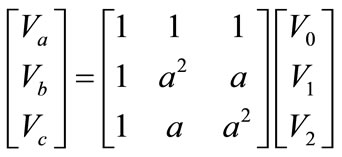
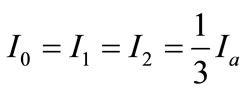
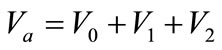
To analyze the power system under unsymmetrical fault conditions, the Symmetrical components method is normally used. Symmetrical components method stats that any unsymmetrical of system with voltage Va, Vb and Vc may be represented by three balanced systems as seen in Figure 1. The zero-sequence components consisting of three phasors with equal magnitudes and zero phase displacement, positive and Negative sequence components, consisting of three phasors with equal magnitudes, ±120˚ phase displacement.
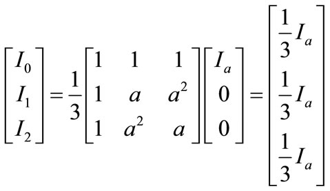
For the simplicity of the following analysis with phase “a”, the subscript “a” will be dropped and denote these sequence components as V0, V1, V2 and they are defined by the following transformation [12]:
 (1)
(1)
where,
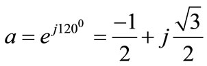 (2)
(2)
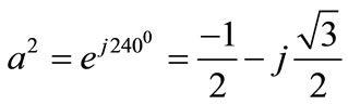 (3)
(3)
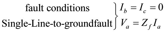
Assume that the unloaded generator with its neutral grounded impedance (Zn) and let the fault impedance be Zf as shown in Figure 2. Considering the fault conditions, the currents and voltages can be given as [13],
 (4)
(4)
Then,
 (5)
(5)
 (6)
(6)
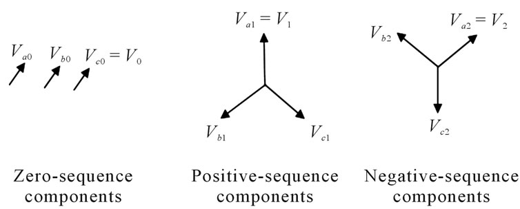
Figure 1. Pharos of symmetrical sequence components.
Figure 2. Single line to ground fault on unloaded generator.
 (7)
(7)
 (8)
(8)
which gives,
 (9)
(9)
where, Vf is the voltage of fault point before fault occurs. Therefore, fault current is,
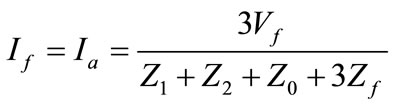 (10)
(10)
Referring to Figure 2, it may be recalled that,
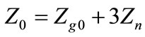 (11)
(11)
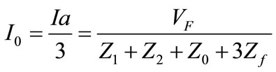
Thus, for the bolted short-circuit ( ) and solidly grounded generator (
 &
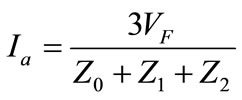
& ), the fault current is given by Equations (12) and (13) respectively,
 (12)
(12)
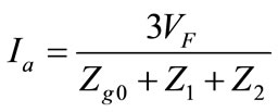 (13)
(13)
If the neutral of generator is isolated, hence , then the fault current is zero. Equation (12) shows that the three sequence impedance are connected in series for the solution of currents under fault conditions.
For a power system with m-buses the bus relation between voltage and current may be represented as bus impedance matrix given in Equation (14). Unlike the bus admittance matrix, the bus impedance matrix cannot be formed by simple examination of the network circuit. It can be formed by direct inversion of the admittance matrix, open circuit testing, and step-by-step formation or graph theory [13].
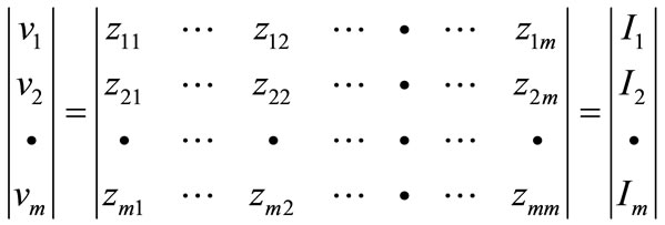 (14)
(14)
Considering the fault case as given in Figure 2 for bus m, the sequence components of the line-to-ground voltages at any bus m during a fault at bus “n” are given by,
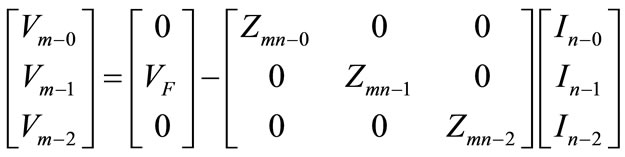 (15)
(15)
Therefore, the short-circuit calculations with bus impedance matrix for symmetrical components of a fault current (Single line to ground fault) is,
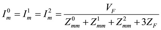 (16)
(16)
where,  ,
,  and
and  are the diagonal elements in the m axis of the corresponding impedance matrix and
  is the prefault voltage at bus m.
3. Effectively Grounded Systems
The term “effectively grounded” has replaced the older term “solidly grounded,” for reasons of definition. In all voltage classes, effectively grounded systems are less expensive than any other type of grounding. This is because no auxiliary grounding devices in the form of resistors, reactors, neutralizers, etc., are ordinarily required. On an effectively grounded system all faults including grounds must be cleared by opening the line. The ground fault currents close to the grounding points arc high, in some cases exceeding the three phase short circuit currents. In a few instances, higher interrupting capacity breakers may be required over that necessary for threephase short-circuit interruption. The higher currents also produce more conductors burning and result in lower positive-sequence voltages with a tendency toward a lower stability limit for line-to-ground faults.
A transformer neutral may be effectively grounded in that there may be no impedance between the neutral and earth. However, the transformer capacity may be too small compared to the size of the system to be effective in stabilizing the voltages from phases to ground, when ground faults occur. This is particularly the case when small grounding transformers are used to provide a source of ground current for relaying [14]. Usually, transformers in generating stations are connected delta on the generator side and grounded star on the high voltage side. Practice varies with regard to step-down transformers, some being connected star and others delta on the high voltage side. For a system effectively grounded, all points on the system or in specified portion, the ratio of zero-sequence reactance to positive-sequence reactance is not greater than “three” while the ratio of zero-sequence resistance to positive-sequence reactance is not greater than “one” for any operational condition, the system may be considered as effectively grounded [15] when the following conditions are met,
 (17)
(17)
where —Zero sequence reactance;
 —Zero sequence resistance;
 —positive sequence reactance.
Ground fault factor is defined as the ratio of the highest voltage to ground  (rms), of the healthy phase or phases during a ground fault to the corresponding power frequency phase voltage “
 ”. It is an important indicator that measures the grounding condition of a system and helps to determine the most appropriate ground fault protective scheme as well as the insulation level for that system. A system is said to be effectively grounded if the GFF does not exceed 80%. GFF is usually more than “one” [16] and can be found by,
 (18)
(18)
4. Time Setting of Protection System
A power transformer is an important and expensive component of a power system that should be correctly protected. Several of protective schemes are practically depending on transformer connections, availability of current transformers, zero-sequence current source, system design, and operating practices. When a fault occurs in power transformer such as short circuits, this fault will be cleared by over current (OC), earth fault (EF) or differential protection. OC relays are used as short circuit protection and some aspects must be considered at the setting of such protection. For example, the current settings shall be high enough not to risk maloperation at maximum load currents. On the other hand, be low enough to give secure operation at minimum fault current (Tripping requirement) [17]. Sensitive detection of ground faults can be obtained by differential relays or OC relays specifically applied for that purpose. Differential protection relays are used for busbars, transformers and feeders to give instantaneous primary protection of the equipments. It measures the difference in current and only responds to faults within a certain zone. The network operating current to the relays is the difference between input and output currents to the network transformer zone of protection [9].
A typical inverse time OC relay has two values to be set, the pick up current ( ) and time multiplier setting (TMS). The pick up current value is the minimum current value for which the relay operates. As for the TMS, it should be in the range of 0.1 - 0.9. The tripping currents of the relays are varied according to the tripping time required and the characteristics of other protection devices used in the network. Therefore, IEC 60255 defines a number of standard characteristics such as; Standard Inverse (SI), Very Inverse (VI), Extremely Inverse (EI) and Definite Time (DT). According to the type of relay as given in Table 1, the operating time of protection (OTP) can be adjusted using the curve characteristics [10,17] as shown in Figures 3 and 4 for transformer (90 MVA) and these characteristics are calculated by the following equation,
 (19)
(19)
Table 1. Type of relay based on transformer capacity.
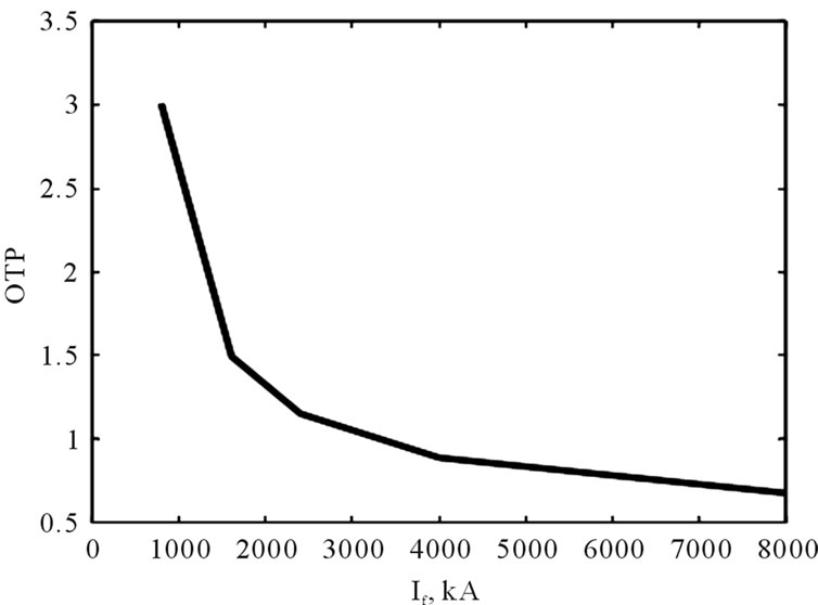
Figure 3. Characteristics of OC relay for power transformer (90 MVA).
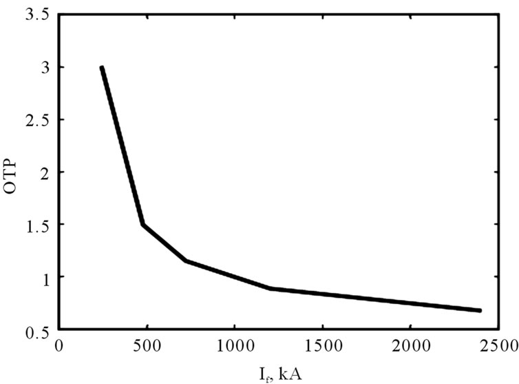
Figure 4. Characteristics of EF relay for power transformer (90 MVA).
5. Approach to Reliability Evaluation Based on GP
The 132 kV transmission system of Babil City is one sector of Iraqi National Grid (132 kV). This system was selected as a case study to implement the developed coding in order to analyze and determine the optimal location of GP. The data of demand and generation was registered during January 2007. A flow chart of the developed computer algorithm in this work is demonstrated in Figure 5. As seen from this chart, firstly, the positive,
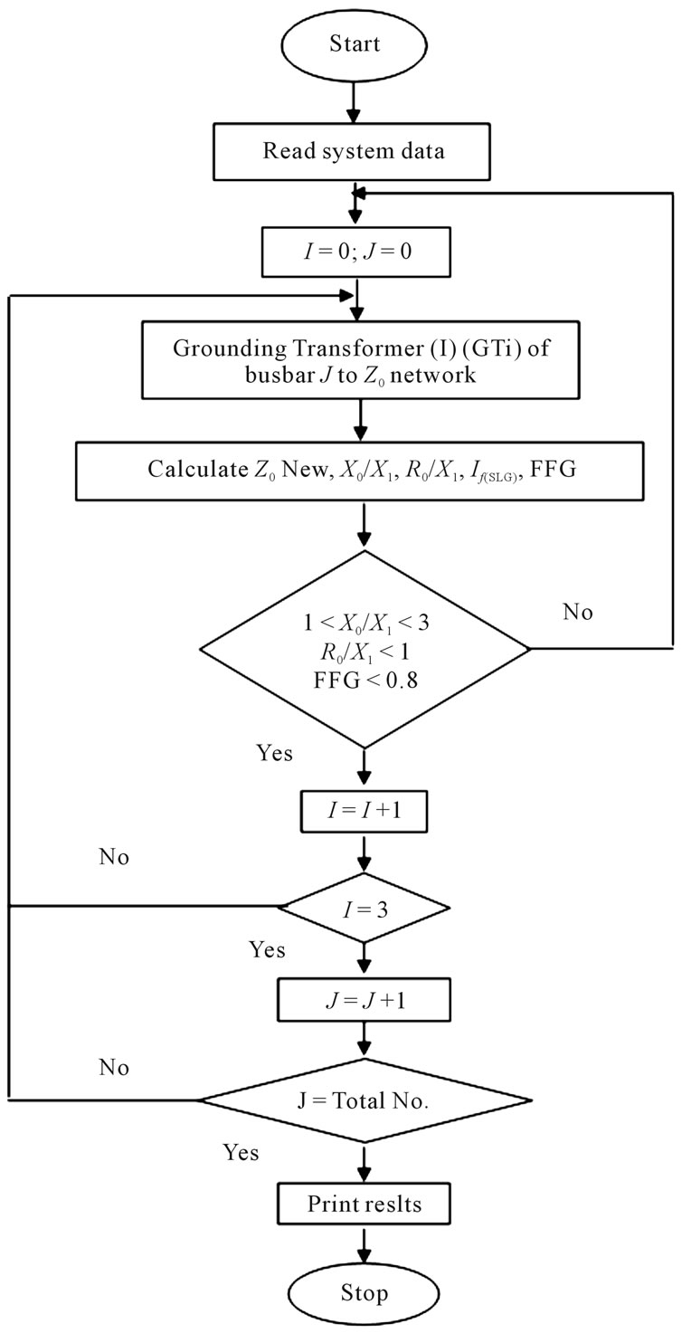
Figure 5. Grounding location to select the operating time of relay.
negative and zero sequence of admittance matrices are composed for the network including the grounding of transformers. After that, the fault currents are calculated. Then, the operating times of OC and EF relays during fault are computed according to the type of grounding and operation characteristic of relays as illustrated in Section 4. Finally, the curve of GFF and fault currents for all stations are used to select the best grounding point in order to choose the fast operating time of relay. The flow chart in Figure 5 can be simplified as given in the following procedures:
1) Calculate the value of  for positive and negative sequence impedance;
2) Calculate the value of  for zero impedance after grounding one transformer in one of substations taking into account all the possibilities of transformer’s grounding in the other substations. Then, calculate the ratios X0/X1 and R0/X1, and the GFF with the fault currents.
3) Repeat step 1) equivalent to the number of transformers involved in this substation 4) Repeat steps 1) and 2) for other substations.
6. Results and Discussion
The evaluation study has been conducted on the 132 kV networks of Babil city. The networks of this city consists of 8 buses and 19 transmission lines, the single line diagram is shown in Figure 6. Jurif Al-saqr is on of the substations located on the networks of Babil city. In this substation, there are three power transformers with rated capacity on 63 MVA. The GPs of this system were selected based on engineering experience. Therefore, this study presents a practical solution for the optimal selection of GPs which is considered an important issue for the operation and safety of a power system.
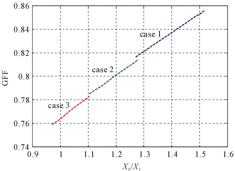
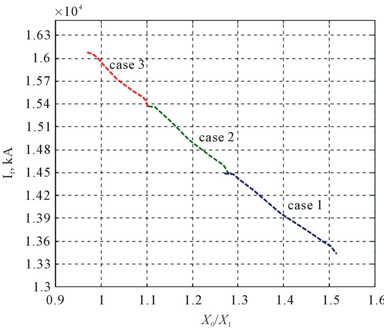
The simulations of GPs were carried out for some cases as demonstrated in Table 2 and graphically shown in Figures 7 and 8. The same simulations of GPs were carried out on the other substations of Babil networks and the summarized results are illustrated in Tables 3 and 4. Referring to Table 2, the relation between GFF and the ratio of sequence reactance are seen in Figure 7, while Figure 8 shows the relation between fault current and the ratio of sequence reactance. From these figures, it can be noted that, when the value of X0/X1 is less than 1.188 and greater than 1, the system is effectively grounded and the fault current is limited between 14933.34 and 15925.78 Amp.
Table 3 shows other scenarios in which five simulated cases have been considered for each substation. For example, when one transformer is grounded in each substation of Hindiya Barag, Latifiyah, Iskandarya, Hashmya and two transformers in other region are grounded, the value of X0/X1 will be at a limited range of “1 - 3” except Iskandarya which is “0.742”. The value of X0/X1 “1.185” for Jurif Al-saqr was selected because the conditions for others substations are met. Therefore, this grounding is an optimal, the shaded cell in Table 3, column 3 shows this value.
The calculated fault current presented in Table 4 is belonging to the five simulated cases of GPs as demonstrated in Table 3. From the calculated values of X0/X1 and fault current with the information presented in Table 1, the OTP of OC and EF can be obtained by applying Equation (19). An example is given for Hindiya Barag substation, the transformer capacity is 63 MVA and the value of fault current is 694.59 A. Referring to Table 1,
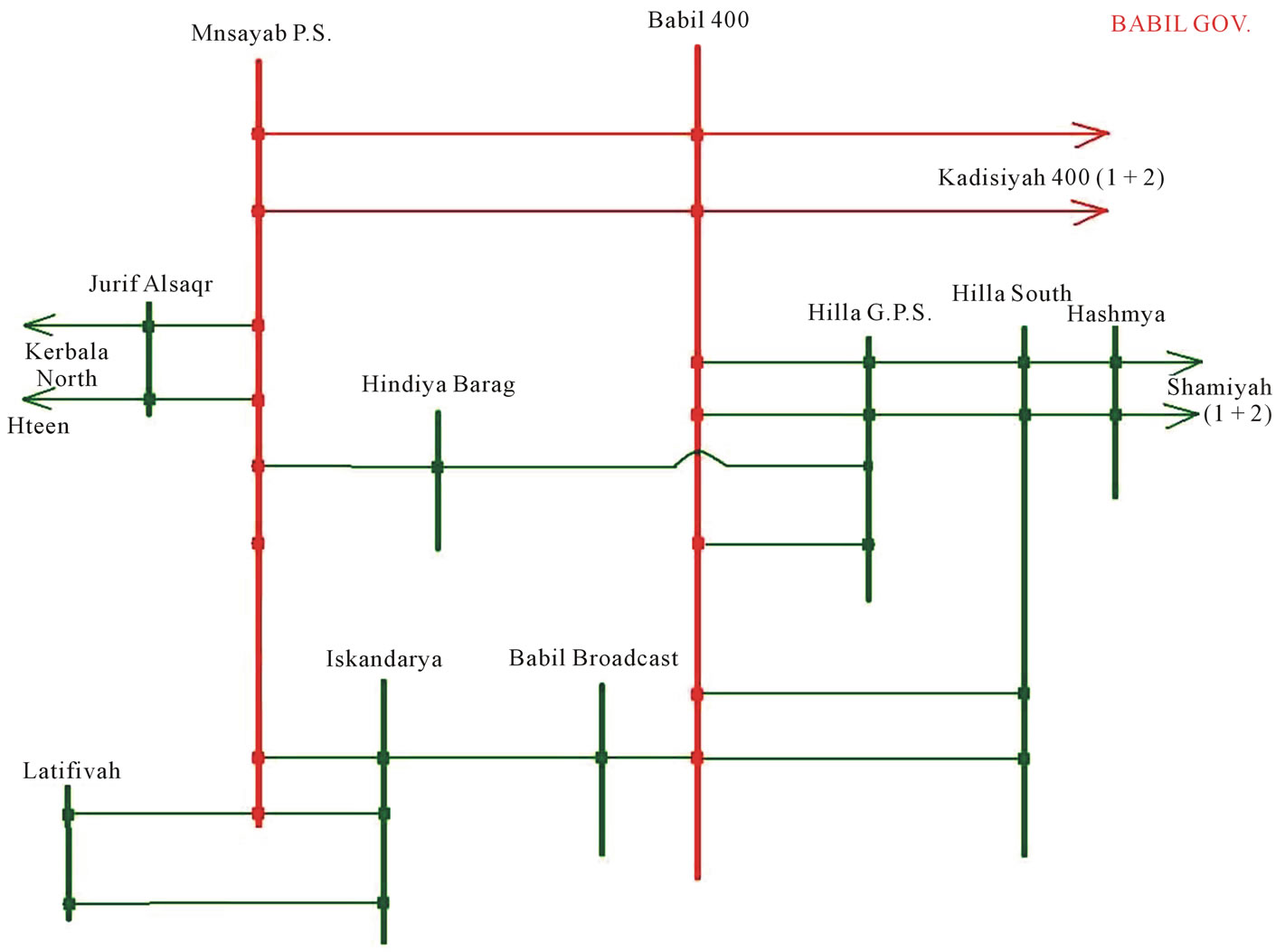
Figure 6. Single line diagram of Babil City.
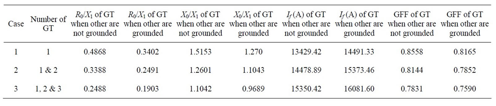
Table 2. Simulated cases of grounded transformers (GT) for Jurif Al-saqr substation.
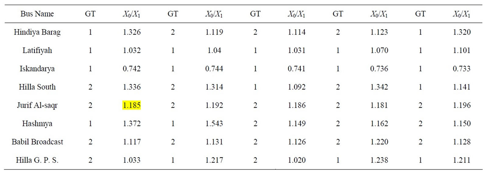
Table 3. Simulated cases of grounding location in different substations.
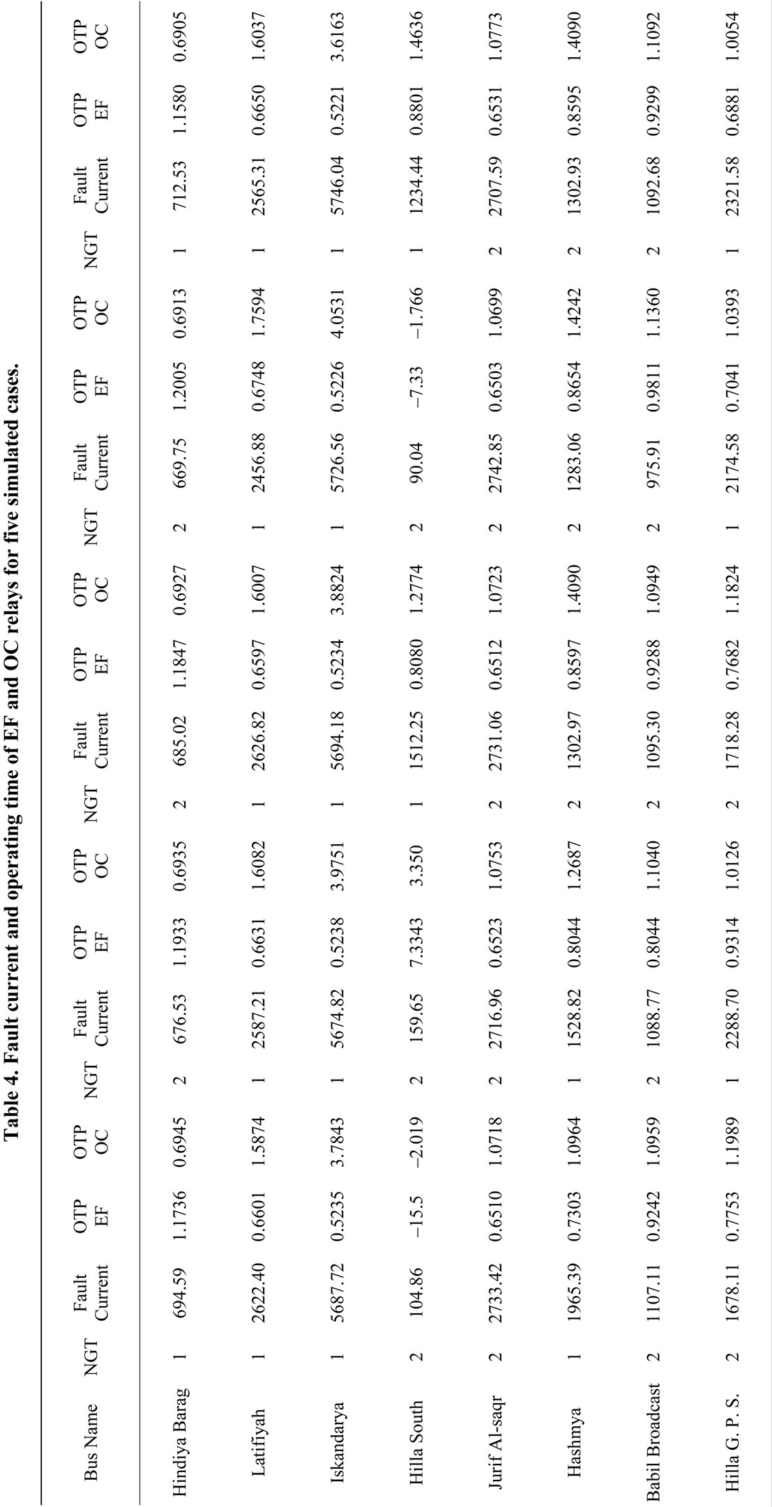
the specifications of OC relay are; TMS = 0.3, IP = 15 and CT = 300/5. As for EF relay, the specifications are; TMS = 0.3, IP = 1.5, CT = 300/5. Thus, the operating time of OC relay is 0.69459 sec and for EF relay is 1.1736 sec; these values are seen in Table 4.
7. Conclusions
In the present work, an attempt to develop a philosophy for grounding system of Iraqi Grid System has been presented. Three approaches were considered are; the ratio of X0/X1, R0/X1 and GFF. Some observations on the obtained results of the proposed grounding approaches are given below:
1) In certain areas of grid system, the ratio (X0/X1) could not be achieved, whatever the number of grounding points was.
2) The ratio (X0/X1) and GFF decreased with the increasing number of grounding points. And the effect of this decreased would become less as the grounded stations or the grounding points are far away than the considered station for testing.
3) The substations with a large number of connections will have a high fault current. On the other hand, this current can be reduced by decreasing the number of grounding points in the substation or the neighborly substations.
4) The substation in which the fault current is low, the relays would not be able to sense it. However, this current could be raised by increasing the number of grounding points in the substation or the neighborly substations.
5) In some substations, the GFF could be taken as criteria to evaluate the effective of grounding where the evaluation by ratio criteria (X0/X1) could not be achieved.
6) The operated time of relay can be used as an indication for selecting the best grounding point.
7) In all simulated cases, the value of the ratio (R0/X1) is not changed, therefore, the resistance was neglected during calculations.
REFERENCES
- J. Sykes, V. Madani, J. Burger, M. Adamiak and W. Premerlani, “Reliability of Protection Systems (What Are the Real Concerns),” Proceeding of IEEE conference on Protective Relay Engineers, College Station, 29 March-1 April 2010, pp. 1-16.
- D. Jacob and K. Nithiyananthan, “Effective Methods for Power Systems Grounding,” WSEAS Transactions on Business and Economics, Vol. 5, No. 1, 2008, pp. 151- 160.
- D. D. Shipp and F. J. Angelini, “Characteristics of Different Power Systems Neutral Grounding Techniques: Facts and Fiction,” IEEE Industry Technical Conference, Seattle, 18-22 June 1990, pp. 107-116.
- D. Paul and S. I. Venugopalan, “Low-Resistance Grounding Method for Medium Voltage Power Systems,” Industry Applications Society Annual Meeting of IEEE Conference, Dearborn, 28 September-4 October 1991, pp. 1571-1578.
- J. Roberts and J. H. Aituve, “Review of Ground Fault Protection Methods for Grounded, Ungrounded, and Compensated Distribution Systems,” SEL, 2001.
- S. Hanninen, “Single Phase Earth Faults in High Impedance Grounded Networks Characteristics, Indication and Location,” Valtion Teknillinen Tutkimuskeskus Technical Research Centre of Finland, Espoo, 2001.
- L. A. Kojovic, T. R. Day and H. H. Chu, “Effectiveness of Restricted Ground Fault Protection with Different Relay Types,” Power Engineering Society General Meeting, IEEE, 13-17 July 2003, pp. 1-6.
- M. Jinxi and F. P. Dawalibi, “Grounding Analysis of a Large Electric Power Station,” IEEE International Conference on Power System Technology, Chongqing, 22-26 October 2006, pp. 1-6.
- J. C. Whitaker, “AC Power Systems Handbook,” CRC Press LLC, Boca Raton, 1999.
- BA THS/BU Transmission Systems and Substation, “Protection Application Handbook,” ABB Support, 1990.
- C. R. Bayliss, “Transmission and Distribution Electrical Engineering,” Antony Rowe Ltd., Chippenham, 2005.
- E. Lakervi and E. J. Holmes, “Electricity Distribution Network Design,” England Short Run Press Ltd., Exeter, 2003.
- H. Saadat, “Power System Analysis,” McGraw-Hill, New York, 1999.
- K. C. Agrawal, “Industrial Power Engineering and Applications Handbook,” University of Michigan, Ann Arbor, 2001.
- Y. Y. Wang and X. J. Zeng, “Grourding Faurt Protection with Sampling Value Difference in Ineffectively Earthed Power Systems,” International Conference on Power System Technology, Chongqing, 22-26 October 2006. doi:10.1109/ICPST.2006.321438
- S. B. Griscom, “Grounding of Power System Neutrals,” ABB Power T & D Company Inc., Raleigh, 1997.
- ANSI/IEEE Std 242, “IEEE Buff Book_Protection & Coordination,” IEEE Transactions, 2000.