Energy and Power Engineering
Vol. 4 No. 2 (2012) , Article ID: 18020 , 10 pages DOI:10.4236/epe.2012.42010
Experimentation of a Plane Solar Integrated Collector Storage Water Heater
Research Unit, Environment, Catalysis and Analysis of Processes National School of Engineers of Gabès (E.N.I.G), University of Gabès, Medenine, Tunisia
Email: Romdhaneb.slama@gmail.com
Received April 19, 2011; revised June 10, 2011; accepted June 20, 2011
Keywords: Heating of Water; Solar Energy; Storage Collector; Tests
ABSTRACT
In order to popularize the use of the solar-water heaters, especially in the residential and tertiary sectors with the third world, it appears to be necessary to reduce their cost while improving their performances. It is the object of this integrated storage collector thus created and tested in the south of Tunisia. It is simply made up of a tank playing the double part of solar absorber and storage tank of warm water, of a glazing to profit from the greenhouse effect and of an insulating case. Its measured energy performances, by the method of input-output proves its effectiveness to produce hot water, in spite of its simplicity of manufacture, usage and maintenance. Indeed a temperature of water exceeding 70˚C is reached towards the afternoon True Solar Time, and for an efficiency of 7%. Thus, this type of collector with integrated storage is entirely satisfactory and could be available to larger mass.
1. Introduction
Tunisia, as all the similar countries of latitude profits from an extremely important sunning even in winter. Indeed, solar flux is on average for the country of 3.5 kWh/m²/d in winter and climbs up to 8 kWh/m²/d in summer while passing by 6 kWh/m²/j with the equinoxes. Thus the heating of water can be easily assured by solar energy without any time to claim to reach a satisfaction of 100% of hot water in winter. Solar heating water standard collector with plane integrated storage can be sufficient considering the strong value of fraction of insolation. The systematic recourse to the thermosiphon solar water heater always is thus not justified. Thus our project of design, realization and tests on the integrated storage collector solar water heater since 1990 meets this need well, more especially as it is reliable, inexpensive, and of easy and local construction [1,2]. Contrary to standard water-heater CPC (Compoud Parabolic Concentrator), our collector while being plane collects the totality of the solar radiation (direct and diffuse) without it not being for as much necessary to constantly direct it towards the sun. In a well shone day, the temperature of water can exceed 70˚C. The other side of the coin is night cooling, but actually it does not constitute a handicap because the sunny days are numerous and the fraction of insolation is high in these areas (0.45 < σ < 0.85).
2. Bibliographical Study
The whole of the bibliography evokes various types of solar water heaters:
-Solar water heaters used in the Scandinavian countries where the collector, placed outside on a sloping roof, is coupled with an inside storage balloon to reduce its cooling with the external ambient air. This range requires a pump and a regulation for its operation.
-Thermosiphon solar water heaters where the balloon is located at the top of the balloon thus allowing a diurnal natural circulation of hot water of the collector towards the storage balloon.
-Integrated storage collector solar water heaters type which have various forms: planes, monotubular or multitubular.
To start with the integrated storage collectors category, let’s quote Smyth [3] who summarizes their development on the basis of the parallelepipedic plane collector simple or improved (ICSSWH: Integrated Collector Storage Solar Water Heater) [4,5], with the solar concentrator of various designs (CPC: Compound Parabolic Concentrator) [6] while passing by those which separate the two compartments collector and storage [7-10] while forming the same tank from collector with integrated storage, or those which use a refrigerant to convey the heat of the compartment collector to the compartment storage [9,10].
In addition, Vaxman 1985, Siddiki [6] and Faiman [7] study a plane collector with storage integrated including a slab insulating into its interior to separate the volume of water into two: one for collecting, the other for storage. Mohamad [8] introduced into the integrated storage collector (ISC) a thermal diode to avoid the night circulation of water out of thermosiphon reverses and thus to reduce its cooling which constitutes the greatest handicap of the ICS. Vaxmen [10] experiments an integral compact solar water heater with channel and water tank to mnimise thermal losses.
Goetzberger [11] and Rommel [12] use transparent insulation materials in improved solar water collector for the central European climate. With the polycarbonate honeycomb material, the performance is good in the temperature range of 80˚C to 140˚C.
Hazami [13] built and studied a solar collector storage with a surface of 5 m² and obtain satisfactory results. Henderson [14] studies the natural convection in an air cavity located between the absorber and the cover plate, and in a water cavity formed by the water storage tank. He concludes that a 5 - 10 increase in the angle of inclination for particular latitude would improve the thermal performance of the heater. Smyth [15] proposes an ICS vessel with inner sleever to reduce heat loss at night.
Schmidt et al. [16] studied an ICS with transparent insulation for reduce loss and accuracy the thermal performances. Tripanagnotopoulos [17] use a cylindrical tank which minimizes thermal losses from the absorber to the ambient, and compare it with conventional solar water heater.
Esen [18] experiments a two-phase heating thermosiphon solar collector using different refrigerants.
Tripanagnotopoulos [19] compare ICS solar system with cylindrical water storage tank and different mountings of it in a symmetric CPC or involute reflector trough.
In [20] Tripanagnotopoulos has suggested a type of ICS systems with two horizontal cylindrical storage tanks and studied its performance and thermal losses.
To increase heat retention, Smyth [21] studied an ICS vessel utilizing an inner sleeve arrangement.
The particularity of the CPC compared to the plane ICS is their pressure resistance of water on the one hand, and their reduced night cooling on the other hand. The other side of the coin is that they are more complex to realize than the plane collectors on the one hand. In addition, they use in their concentration only the direct solar radiation; what requires their continuation of the sun normally. But this cannot be possible for the field of heating of low temperature water for obvious economic reasons.
The following Table 1 gives a comparison between the various Integrated Storage Collectors types.
By comparing the various types of ICS, one detects that the best are:
-The plane collectors whose lower part is thin compared to the higher part in order to increase the quantity of water stored in this higher part and to profit from the stratification.
-The Compound Parabolic Concentrator profiting from clear sky of an illumination in any point from surface external of the balloon of storage.
-The existing solar water heaters are characterized mainly by their constitution.
-The plane solar collector whose function is to collect the solar radiation, to transform it into heat, and to transfer it to the liquid coolant (water).
-The hot water storage balloon: these two elements are then connected together to form the standard solar-fired heater with separate elements.
In moderate countries, the hot-water tank is placed inside; a regulation is essential so that the circulating pump is activated if the temperature of the water collector is higher than that of storage. These accessories generate an electric over consumption and a considerable maintenance.
In order to simplify the installations and reduce costs, one prefers to place the balloon of storage raised by plane collector, thus avoiding the use of his regulation and circulating pump, in hot countries. The circulation of water coolant then done naturally by thermosiphon.
Indeed, the Tunisian climate is so favorable for the solar applications. A simple ICS, not sophisticated, can satisfy the requirement out of hot water with an important rate for needs cover.
3. Dimensioning—Design
The rule often used is to consider a water capacity from 50 to 70 liters for a m² of collector. This corresponds to a thickness from 5 to 7 cm.
Prototypes constructed and tested since 1988 in all Tunisia show effectiveness of the system (Figures 1-2). The major technical problem encountered is the corrosion of the storage collector; heated water is no more effective. The materials tested are ordinary steel, galvanized, stainless, but also the glass fibre. The nuance of stainless steel 316 L oxidizes in the presence of tap water, contrary to rainwater (cistern.). As for glass fibre, the mechanical resistance to the level of connections is very weak due to the rise in temperature.
In the design of this ICS, a local heat insulator is used. Its thickness is rather high (8 cm) to compensate for its high thermal conductivity. The fraction of the two sizes constitutes the thermal resistance which remains acceptable.
The ICS can to be with or without exchanger. The direct use of the hot water of the tank makes it possible to reach a temperature of more than 10˚C to 15˚C compared to that from the exchanger; what is important especially in winter. However that requires that the tank is not oxidized.
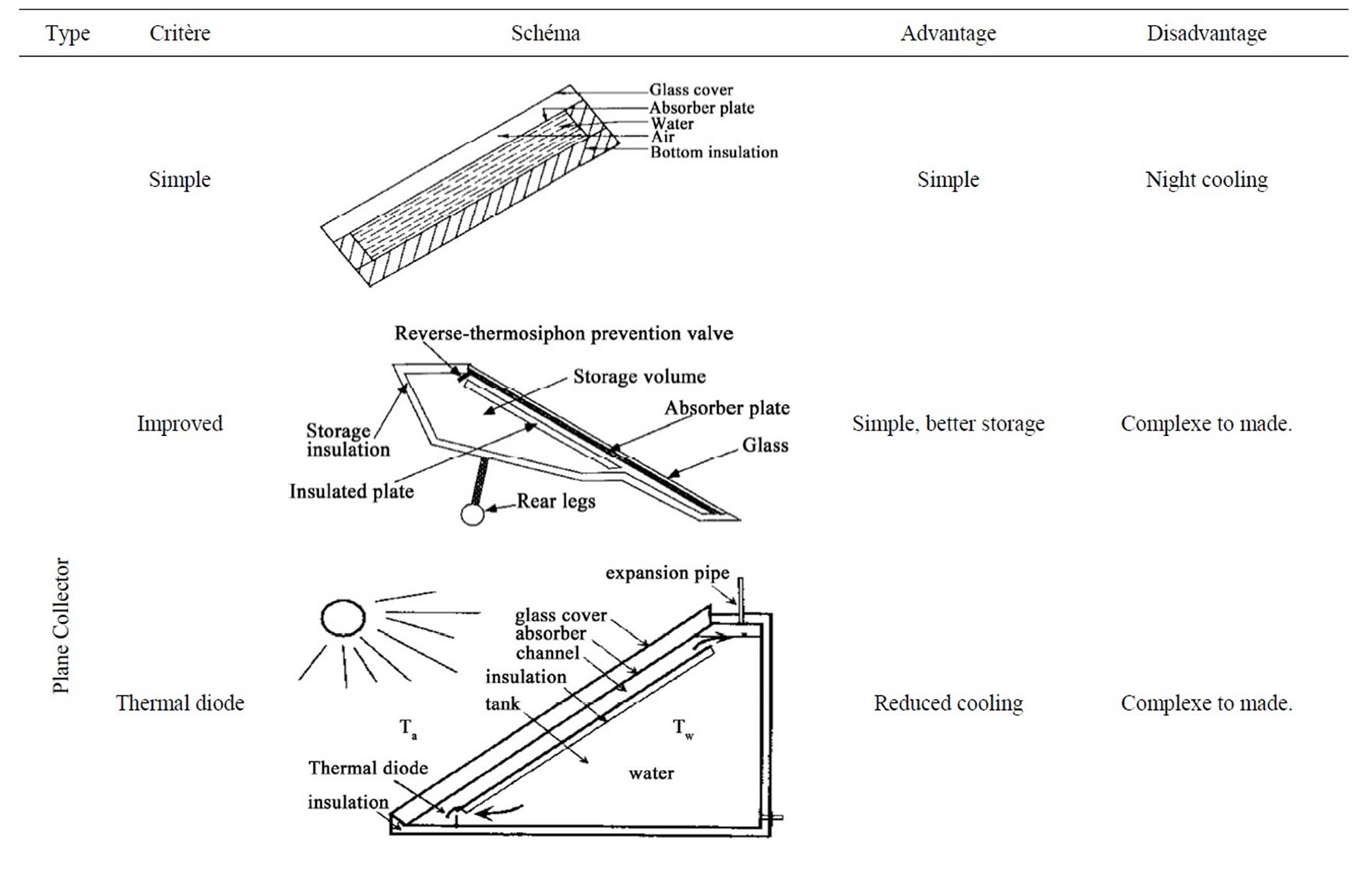
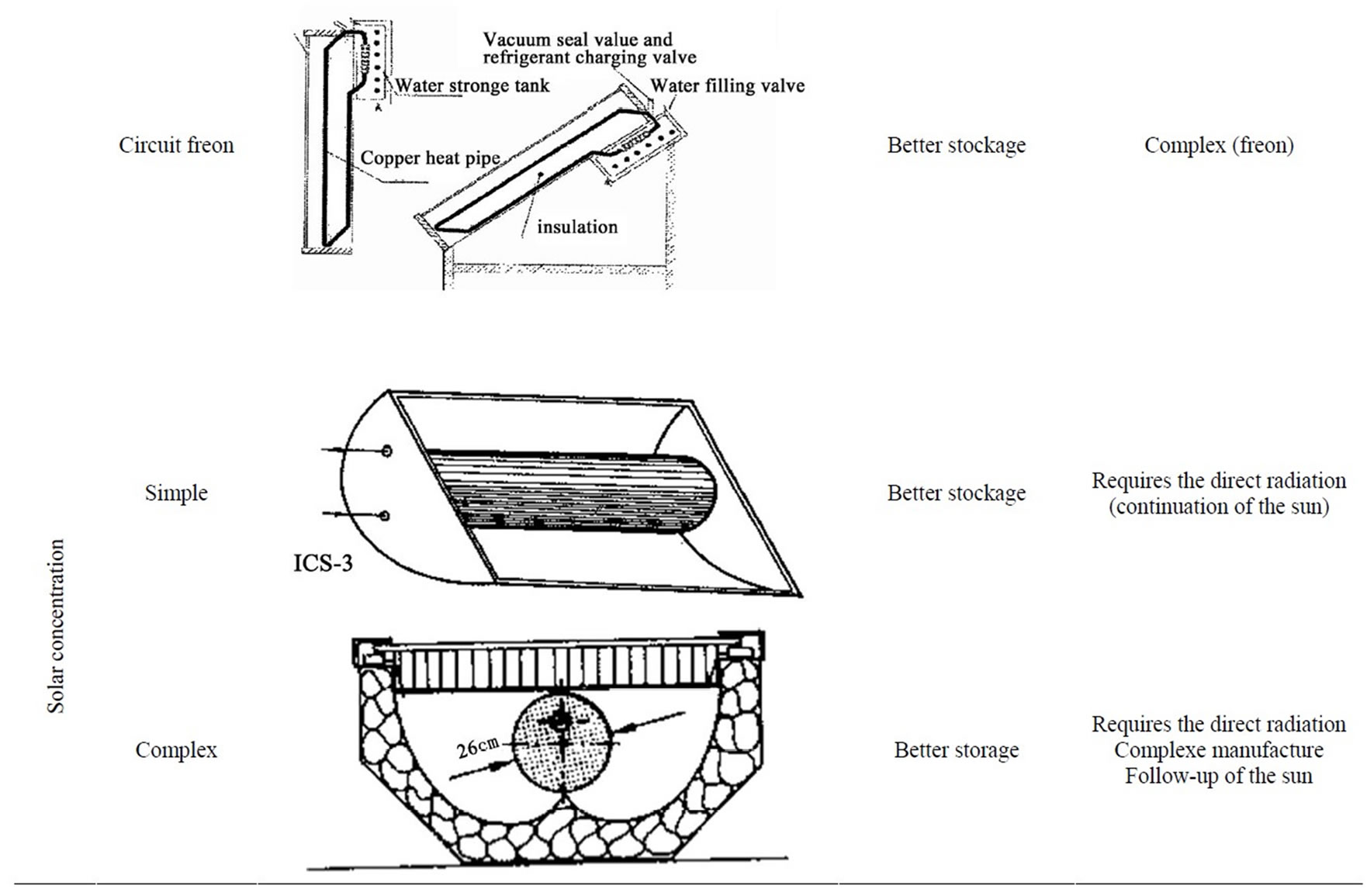
Table 1. Comparison between the various Integrated Storage Collectors types.
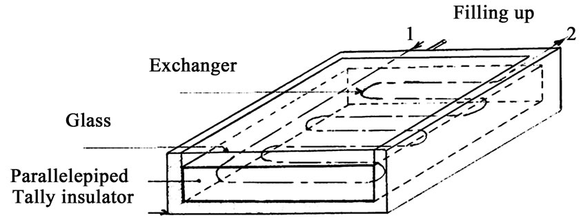
Figure 1. Integrated collector storage with exchanger.
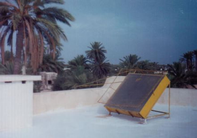
Figure 2. Photo of the ICS realized and installed.
4. Operating Features
These characteristics are very important. They vary according to the slope of the collector and to the climatic conditions on which the user cannot act.
Indeed, in the most of the cases, the solar converters should function in inclined position to intercept the maximum of energy.
This slope has an influence on the operation of these apparatuses from many points of view: radiative exchanges, convectifs exchanges, circulation of the fluid. The optimal slope for our hot countries corresponds to the raised latitude of ten degrees; that is to say around 45˚ for Tunisia.
The influence of the wind speed is not negligible. It intervenes directly on the convectifs exchanges between the cover of the environment. The variation of the wind speed will involve a variation of the front losses.
As for the value of the ambient temperature, it intervenes in the thermal losses of the apparatus, will influence in a direct way the output of the solar furnace. The increase in the ambient temperature involves a reduction in the losses.
 (1)
(1)
5. Determination of Solar Flux by Calculation [22,23]
At a given moment of the day, on a date and in a given place, it is possible to calculate the solar energy received by a solar collector, under conditions of clear sky. To simplify the spots, one gives, which is generally useful: manner of calculating the solar energy, in kWh/m²/d, received by a collector inclined according to an angle “I” compared to the horizontal one (Figure 3).
To know the solar energy received per day by an inclined plane collector of an angle “i” compared to the horizontal one, we calculate successively [20]:
-The height of the sun at true solar midday
 (2)
(2)
The declination of the sun δ (t) is equal to the latitude of the place located between the tropics and for which the solar rays are perpendicular to the horizontal plan at solar midday. Table 2 gives the monthly average of the declination.
-The angle “U” formed between the normal of the collector and the solar rays at solar midday:
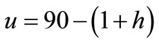 (3)
(3)
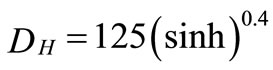
-The direct radiation (i.e. coming directly from the sun and not from the atmosphere), under of clear sky conditions:
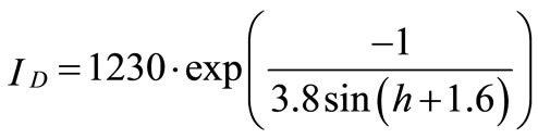 (4)
(4)
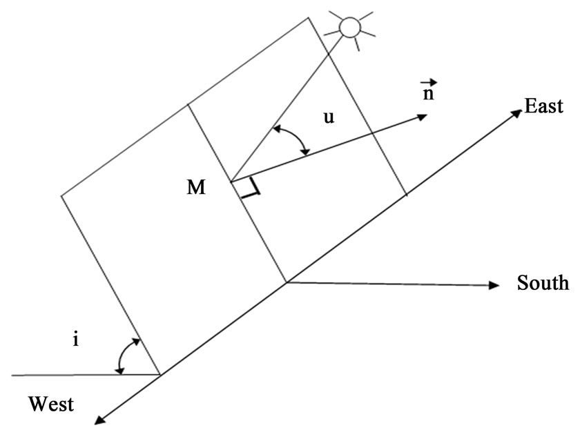
Figure 3. Position of the solar collector at solar midday.
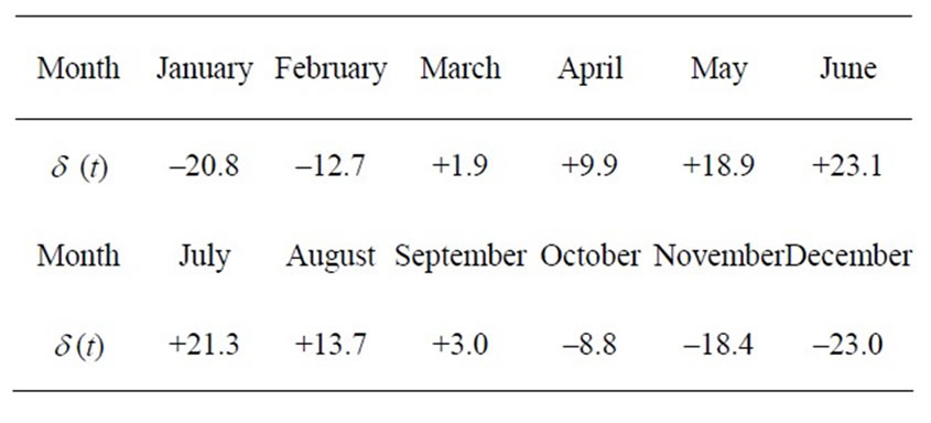
Table 2. Monthly average solar declination.
-The diffused radiation (i.e., emitted or reflected by the atmosphere, the clouds …) received by the horizontal plan in the case of clear sky conditions:
 (5)
(5)
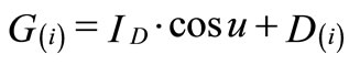
-The total radiation received by the horizontal plan:
 (6)
(6)
-Diffuse and total radiations receipts by the inclined collector plan:
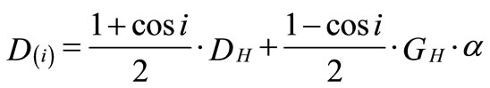 (7)
(7)
 (8)
(8)
The albedo α is the coefficient of reflexion of the ground located in front of the collector (usually taken equal to 0, 2).
-Duration of the day:
 (9)
(9)
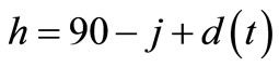
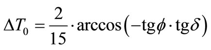
For a solar collector directed constantly towards the south, and for the period located between the 21/3 and the 22/9, the duration of collecting is to be corrected by:
 (10)
(10)
-Finally received energy:
 or
or  (11)
(11)
6. Mathematic Modelling
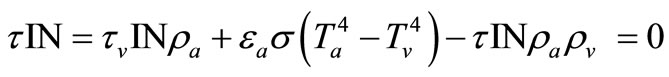
6.1. Assessment on the Surface of the Absorber
This surface absorbs: a fraction of solar radiation IN transmitted by the glass (τ IN), a fraction reflected by the pane of the radiation emitted by black surface (τv IN ρa) and a radiation emitted by the pane because of its temperature Tv towards black surface (τ IN). It emits by its black face , in direction of the glass.
With the thermal balance of the absorber thus results in the equation:
 (12)
(12)
 (13)
(13)
6.2. Assessment on Glass Cover
At the balance we have:
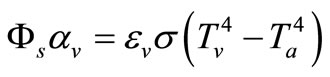 (14)
(14)
 (15)
(15)
 (16)
(16)
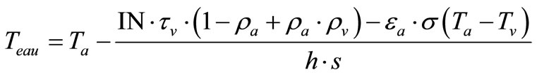
6.3. Assessment of Operation of a Solar Water Collector
In steady state, the energy balance per unit of the collector area is written:
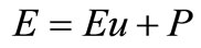 (17)
(17)
with:
E: solar flux absorbed by surface of the absorber (W/m2)
Eu: useful flux received by the fluid (W/m2)
P: lost fluxes by convection and conduction towards the back of the collector and by convection, conduction and radiation forwards collector.
We define the instantaneous efficiency of an collector by:
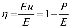 (18)
(18)
Among the losses P, one distinguishes those which depend only on qualities of the collector: optical losses, and those which depend in other on the operating temperature: losses thermics apart from the absorber.
The efficiecy can be also expressed by:
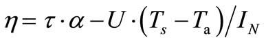 (19)
(19)
Or while basing itself to the real measures (method of input-output).
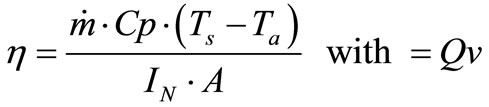 (20)
(20)
7. Results of the Experimental Study [24]
The tests were carried out during May to June 2006, thanks to measuring instruments provided by the ISSAT Gabès, Tunisia. We measured the various climatic parameters such as the ambient temperature, the wind speed, the temperature in the water-heater and the solar flux. The study of our system is made under real conditions of operation.
The collector is directed towards the south of angle of inclination fixed at 45˚.
The level of temperature and the output reached are comparable with what was published by Souliotis [5], Garg [9], Vaxmen [12] and Smyth [15].
7.1. Temperature Measurement
The temperature measurement is made by mercury thermometers. Measurements begin 8 h until 18 h, we recorded at each hour the temperature in three levels of tank (low, medium and high). The average temperature is calculated and the influence of the ambient temperature, wind speed and the incidental solar flux on the profile of the average temperature are studied.
7.2. Measurement of the Solar Radiation
The apparatus used is a photovoltaic silicon cell whose delivered current is proportional to the solar radiation. Its calibration made it possible to find a proportionality factor of 5.22 between solar flux (W/m²) and the current delivered by the cell (Figure 4). This one is placed in the plane of the collector to have the same orientation and the same slope. Measurement is taken every half an hour.
7.3. Determination of the Efficiency
The collector efficiency is measured by the Input-Output method, this one consists in letting the collector warm up during all the day. Each hour, we measure the water temperature on three levels (low, medium and high) and the incidental solar flux.
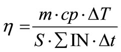 (21)
(21)
with:
m: mass of water CP: specific heat of water T: temperature increase S: absorber surface t: time of measurement IN: incidental solar flux The output enabled us to plot the following curves.
7.3.1. Simple Glazing
The characteristic curve of a solar collector is that of its efficiency according to the standardized gain (rise in temperature brought back to solar flow) (Figure 5). Measurements show that already with a simple glazing, the efficiency reaches 50% for a standardized gain of 0.033, i.e. an increase of 33˚C under a solar flux of 1000 W/m². It is still 30% for a standardized gain of 0.065, the rise in temperature is of 65˚C.
Figure 6 amongst other things shows the evolution of water storage temperature. The difference between the water temperature compared to the ambient one reaches 50˚C in after noon, which is considerable.
The minima of temperature for the ambient and the water of storage are shifted because of the inertia of the ICS. Indeed, in June and for a fixed collector towards the south, for the ambient air, the minimum of temperature is between 3 and 4 h TST, whereas for the ICS water reaches its minimum of temperature to 7 h TST i.e. with the rising of the sun.
In the same way, for the maximum, there is a shift of 4 h approximately, being established towards 13 h for the ambient and at 17 h for the storage water.
As for the sunning, its maximum is to 12 h TST, which is earlier than the ambient air and the water of storage.
It should be noted that, as beyond 12 h, the temperature of water continues to increase during 3 to 4 h, and this is the same if the ICS has a fixed orientation towards the south.
Lastly, it is noted that the storage of heat of the first day increase the temperature of the water of a few degrees for the second day.
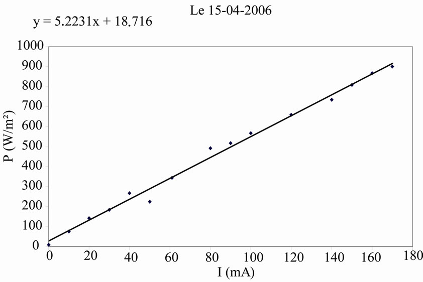
Figure 4. Solar cell calibration curve.
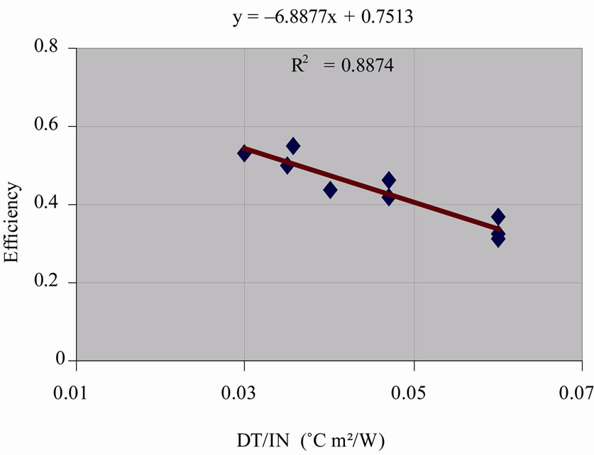
Figure 5. Evolution of efficiency according to standardized gain (Simple glazing).
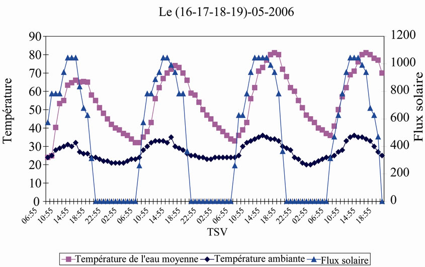
Figure 6. Evolution of temperature according to solar flow during four days.
7.3.2. Double Glazing
With the double glazing, the performances are still better. Even with standardized gain of 0.065, to compare with the simple glazing, the efficiency is still 42%, against 30% for the simple glazing (Figure 7).
The most appreciable interest of the double glazing compared to the simple glazing is the attenuation of the night cooling effect. The difference between the water temperature and the ambient temperature, with the rising of the sun, is 20˚C, against 10˚C respectively (Figure 8). What is quite remarkable, in spite of the simplicity of the system. Finally, let us note that the glazing used is of the ordinary and no selective type.
7.4. Study of Racking
To determine the production of hot water of the collector, we have fixed the temperature of racking at 45˚C since this latter is sufficient for domestic use.
Each hour we measure the of the water tank temperature in low, medium and high, we determine the average
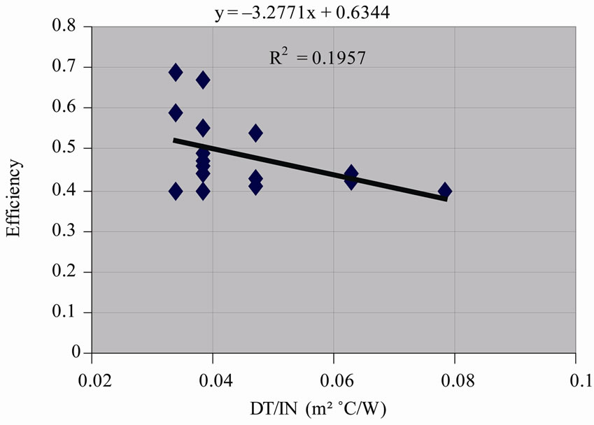
Figure 7. Evolution of energetic efficiency according to the standardized gain (Double glazing).
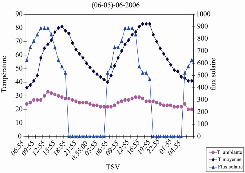
Figure 8. Evolution of temperature according to solar flux during two consecutive days.
temperature as soon as the desired temperature is reached; we made the total draining of the of the water tank volume.
The temperature of the three levels of the tank since there is stratification of the layers i.e. superposition of increasing layers of temperature. Thanks to this method, one determined the daily efficiency (Figures 9, 10).
In addition, the efficiency of the collector increases with the quantity of heated water, even if the level of temperature decreases because it is precisely where thermal - losses of ISC are reduced.
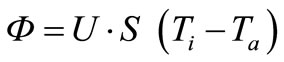
7.5. Thermal Losses Coefficient
To determine the thermal coefficient of of the system loss, he ICS is let heat all day. We measure the temperature in low, medium and high of the tank to 19 h and we determine the average temperature, one lets the system cool during the night, to 7 a.m. we measure and determine the average temperature.
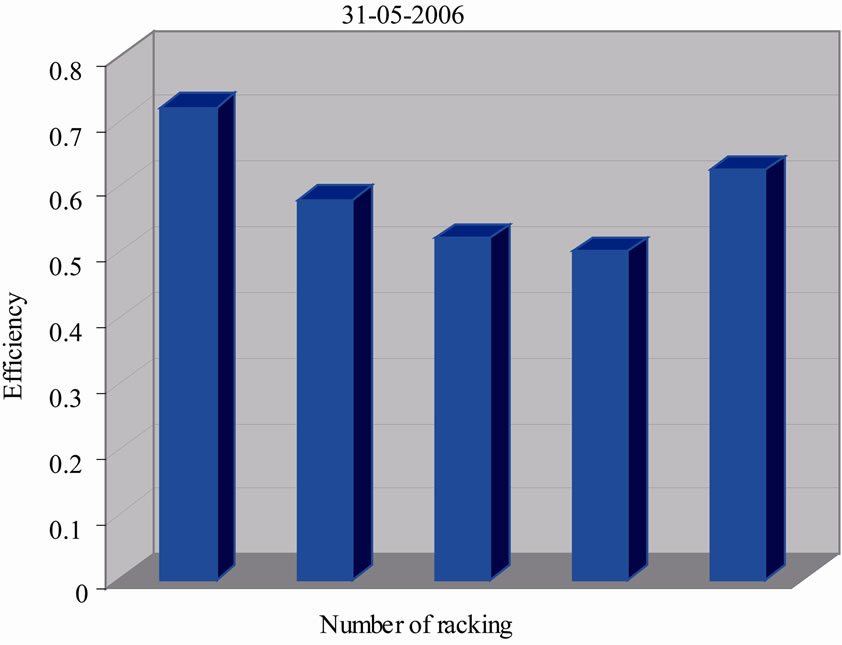
Figure 9. Evolution of efficiency according to the daily number of racking.
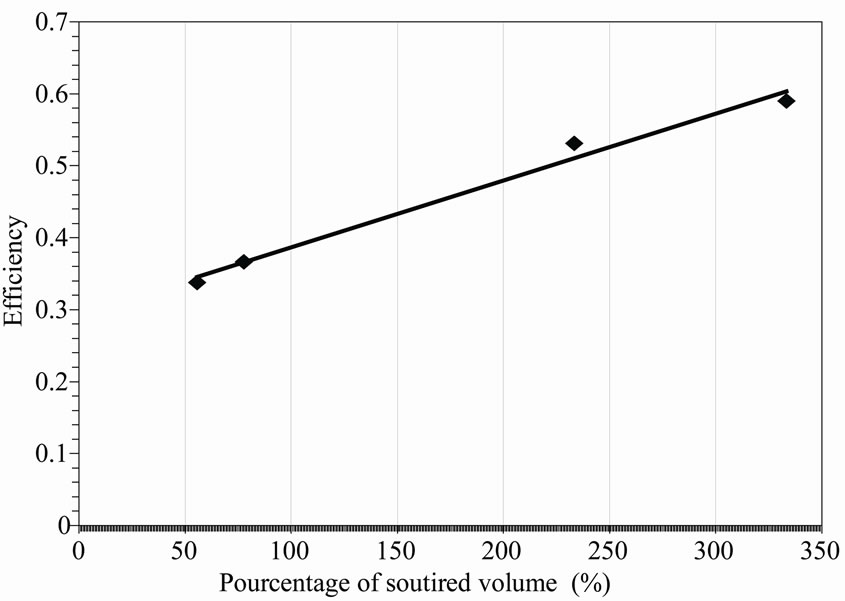
Figure 10. Curves of efficiency according to the volume of tapped water V = 9 litres.
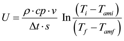 (22)
(22)
Calculation of U:
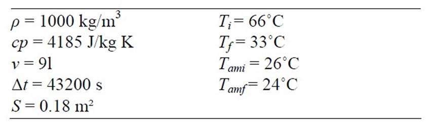
From where: U = 5 W/m²k.
We notice that the coefficient of the losses during the night increases proportionally with the speed of wind. We can say that the wind speed has a great effect on the losses coefficient U during the night as shows it the following Figure 11.
8. Conclusions
In the climate of southern Tunisian, shone upon so well, all the year, we wanted to show that a simple ICS can give satisfaction, while answering the economic requirements and maintenance.
The theoretical and experimental study proves that the plane solar water heater with integrated storage is powerful for the quite sunny sites, or more generally for the quite sunny days whatever the place, even Scandinavian. The results of our measurements join those carried out with the test bench of the INRST Tunis since 1990. A rise in temperature of 44˚C is exceeded and a temperature of 84˚C is reached. The interest of the double glazing is certain to contribute to mitigate the constraint of night cooling. The profit, with the rising of the sun, is 10˚C compared to the simple glazing.
To avoid night cooling we used a double glazing. Other authors use a thermal diode. However, as this type of water-heater is rather intended for the quite sunny countries, it is better to use hot water the very same day not to worry about its posterior cooling nor to resort to complex
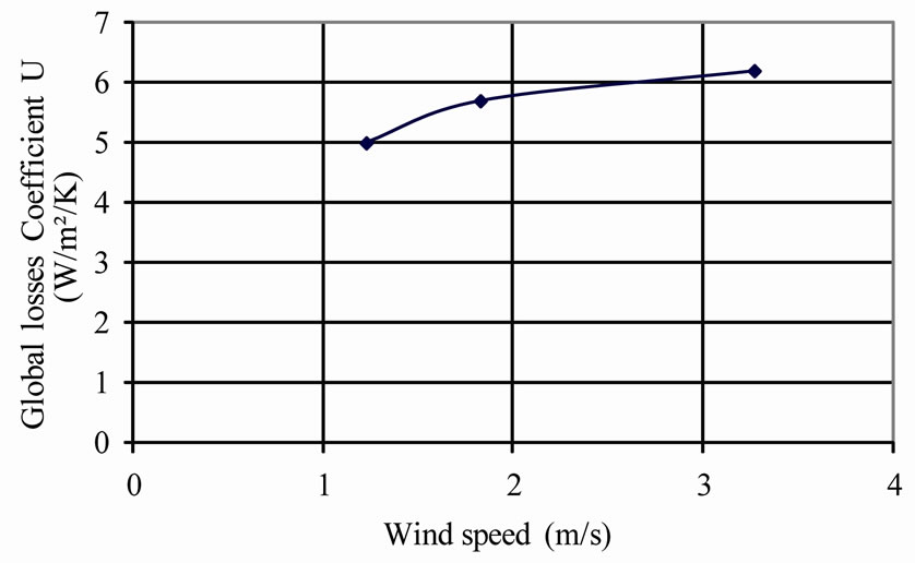
Figure 11. Evolution of the loss ratio according to speed of wind, June 15 to 17, 2006.
remedies leaving the sought objective for this of sensor for integrated storage collector type.
REFERENCES
- R. Ben Slama, “Integrated Storage Collector Solar Water Heater,” Technical Opinion I.N.R.S.T., Soliman-Tunisia, 1990.
- R. Ben Slama, “Integrated Storage Collector Solar Water Heater,” Brevêt of Invention NSN 89025 (16120) INNORPI, 1990.
- M. Smyth, P. C. Eames and B. Norton, “Integrated Collector Storage Solar Water Heaters,” Renewable and Sustainable Energy Reviews, Vol. 10, No. 6, 2006, pp. 503-538. doi:10.1016/j.rser.2004.11.001
- S. C. Kaushik, R. Kumar, H. P. Garg and J. Prakash, “Transient Analysis of a Triangular Built-in-Storage Solar Water Heater Under Winter Conditions,” Heat Recovery Syst CHP, Vol. 14, No. 4, 1994, pp. 337-341. doi:10.1016/0890-4332(94)90037-X
- Y. Souliotis and Y. Tripanagnostopoulos, “Experimental Study of CPC Type ICS Solar Systems,” Solar Energy, Vol. 76, No. 4, 2003, pp. 389-408. doi:10.1016/j.solener.2003.10.003
- K. M. Siddiqui and C. Z. M. Kimanbo, “Development of Compact Integral Solar Water Heater for Africa,” Renewable Energy, Vol. 4, No. 4, 1994, pp. 395-400. doi:10.1016/0960-1481(94)90046-9
- D. Faiman, H. Hazan and I. Laufer, “Reducing the Heat Loss at Night from Solar Water Heaters of the Integrated Collector-Storage Variety,” Solar Energy, Vol. 71, No. 2, 2001, pp. 87-93. doi:10.1016/S0038-092X(01)00021-4
- A. A. Mohamed, “Integrated Solar Collector-Storage Tank System with Thermal Diode,” Solar Energy, Vol. 61, No. 3, 1997, pp. 211-218. doi:10.1016/S0038-092X(97)00046-7
- H. P. Garg and U. Ranu, “Theoretical and Experimental Studies on Collector/Storage Type Solar Water Heater,” Solar Energy, Vol. 29, No. 6, 1982, pp. 467-478. doi:10.1016/0038-092X(82)90055-X
- A. Gotzberger and M. Rommel, “Prospects for Integrated Storage Collector Systems in Central Europe,” Solar Energy, Vol. 39, No. 3, 1987, pp. 211-219. doi:10.1016/S0038-092X(87)80030-0
- M. Rommel and A. Wagner, “Application of transparent Insulation Materials in Improved Flat-Plate Collectors and Integrated Collector Storage,” Solar Energy, Vol. 49, No. 5, 1992, pp. 371-380. doi:10.1016/0038-092X(92)90109-N
- B. Vaxmen and M. Sokolov, ”Experiments with an Integral Compact Solar Water Heater,” Solar Energy, Vol. 34, No. 6, 1985, pp. 447-454. doi:10.1016/0038-092X(85)90018-0
- M. Hazami, S. Kooli, et al., “Performance of a Solar Storage Collector,” Desalination, Vol. 183, No. 1-3, 2005, pp. 167-172. doi:10.1016/j.desal.2005.03.033
- D. Hendersuon, H. Junaidi, et al., “Experimental and CFD Investigation of an ICSSWH at Various Inclinations”. Renewable and Sustainable Energy Reviews, Vol. 11, No. 6, 2007, pp. 1087-1116. doi:10.1016/j.rser.2005.11.003
- M. Smyth, P. C Eames and B. Norton, “A Comparative Performance Rating for an Integrated Solar Collector/Storage Vessel with Inner Sleeves to Increase Heat Retention,” Solar Energy, Vol. 66, No. 4, 1999, pp. 291-203. doi:10.1016/S0038-092X(99)00027-4
- C. H. Schmide, A. Goetzberger and J. Schmid, “Test Results and Evaluation of Integrated Collector Storage Systems with Transparent Insulation,” Solar Energy, Vol. 41, No. 5, 1988, pp. 487-494. doi:10.1016/0038-092X(88)90022-9
- Y. Tripanagnotopoulos and P. Yianoulis, “Integrated Collector Storage Systems with Suppressed Thermal Losses,” Solar Energy, Vol. 48, No. 1, 1992, pp. 31-43. doi:10.1016/0038-092X(92)90174-9
- M. Esen and H. Esen, “Experimental Investigation of Two-Phase Closed Thermosiphon Solar Water Heater,” Solar Energy, Vol. 79, No. 5, 2005, pp. 459-468. doi:10.1016/j.solener.2005.01.001
- Y. Tripanagnotopoulos and M. Souliotis, “ICS Solar Systems with Horizontal (E-W) and Vertical (N-S) Cylindrical Water Storage Tanks” Renewable Energy, Vol. 29, No. 1, 2004, pp. 73-96. doi:10.1016/S0960-1481(03)00144-7
- Y. Tripanagnotopoulos and M. Souliotis, “ICS Solar Systems with Two Water Tanks,” Renewable Energy, Vol. 31, No. 11, 2006, pp. 1698-1717. doi:10.1016/j.renene.2005.08.028
- M. Smyth, P. C. Eames, B. Northon, et al., “Technoeconomic Appraisal of an Integrated Collector/Storage Solar Water Heater,” Renewable Energy, Vol. 29, No. 9, 2004, pp. 1503-1514. doi:10.1016/j.renene.2003.10.009
- R. B. Slama, “Measurement and Calculation of the Solar Radiation,” Tunisian Energy Journal, Vol. 44, 1997, pp. 37-43.
- R. Bernard, G. Menguy and M. Schwartz, “The Solar Radiation, Thermal Conversion and Applications,” 2nd Edition, Technique and documentation, Paris, 1980.
- D. Faiman, “Towards a Standard Method for Determining the Efficiency of Integrated Collector-Storage Solar Water Heaters,” Solar Energy, Vol. 33, No. 5, 1984, pp. 459-463. doi:10.1016/0038-092X(84)90199-3
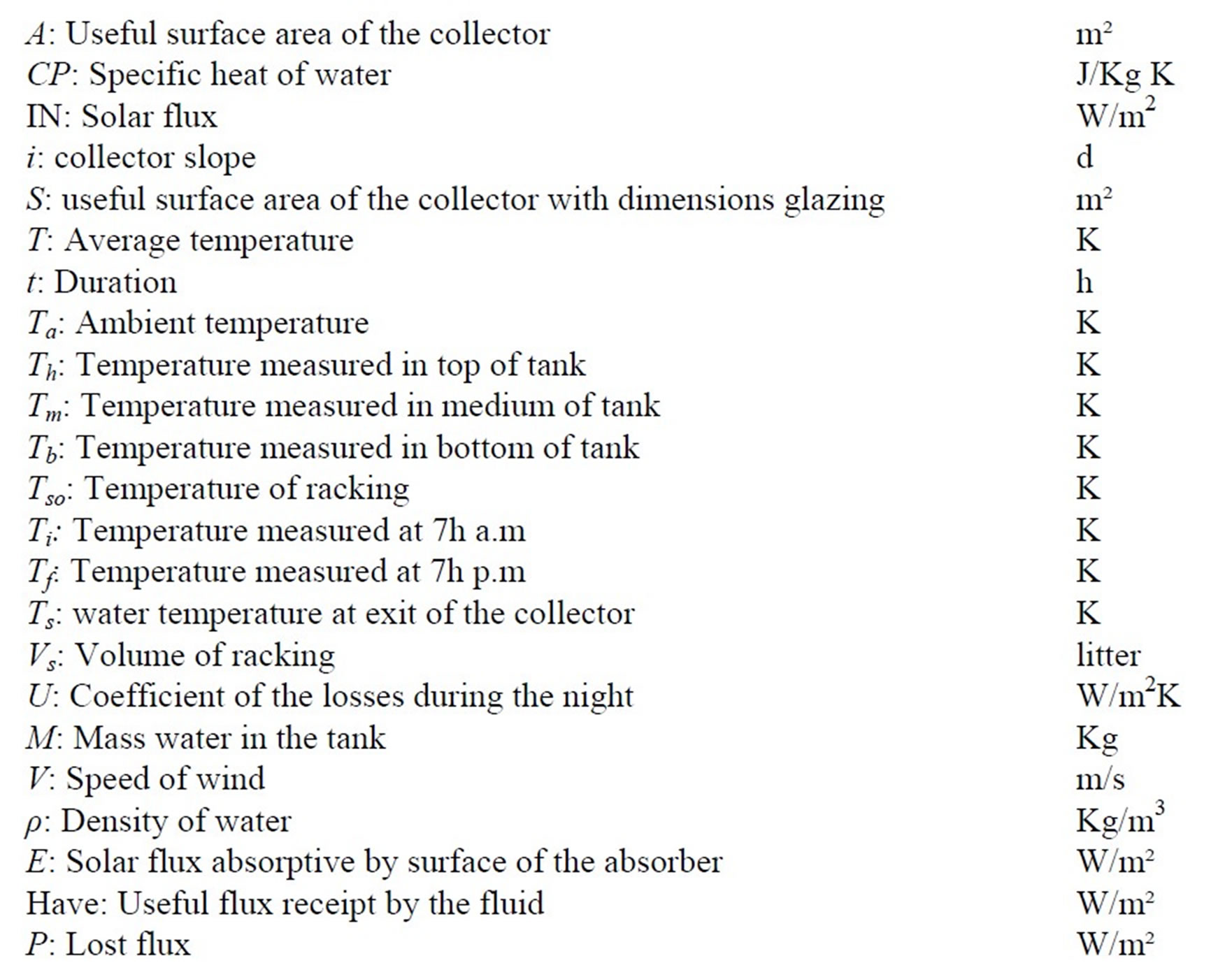
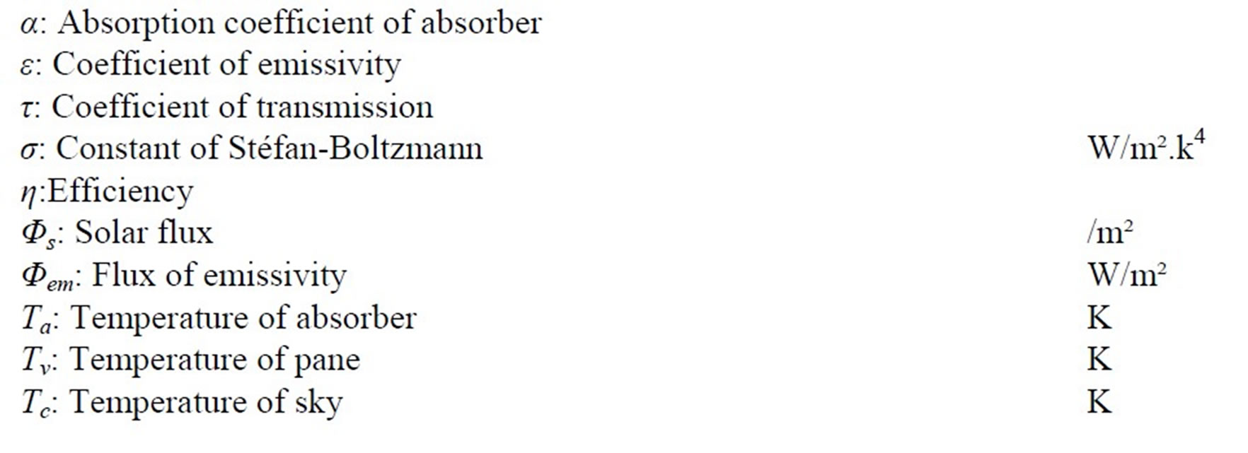
Nomenclature