Communications and Network
Vol. 4 No. 3 (2012) , Article ID: 22068 , 14 pages DOI:10.4236/cn.2012.43025
OFDMA Uplink Frequency Offset Estimation with Multi-Access Interference Mitigation*
Advanced Network Technologies and New Services, University of Science and Technology Beijing (USTB), Beijing, China
Email: zhangzs@ustb.edu.cn, liujian@ustb.edu.cn, #longkeping@ustb.edu.cn
Received May 11, 2012; revised June 15, 2012; accepted July 13, 2012
Keywords: Synchronization; Timing Offset; Frequency Offset; OFDMA
ABSTRACT
In this paper, we consider the frequency offset estimation for Orthogonal Frequency-Division Multiple Access (OFDMA) uplink (UL) transmissions. We first analyze the negative effect of Multi-Access-Interference (MAI) on OFDMA UL, and then propose two interference reduction/elimination methods, i.e., the Reduced-Rank-Projector (RRP) and Shift-Sampling-Projector (SSP) methods, to eliminate/reduce the heavy MAI due to the frequency offsets. Finally, we propose a new training sequence group named the Round-Robin Training Sequence Group (RRTSG), which has a high interference mitigation capabilities for OFDMA UL transmission. The Cramer-Rao Lower Bound (CRLB) for an unbiased frequency offset estimator in a Multiple Access (MA) system is also derived. Numerical results show that the proposed methods are suitable to eliminate/mitigate the effect of the frequency offset on OFDMA UL transmission.
1. Introduction
Orthogonal Frequency-Division Multiple Access (OFDMA) is an effective Multiple Access (MA) scheme that divides the total signal bandwidth into multiple orthogonal subcarrier groups, with each group being allocated to one user [1]. In uplink (UL) transmission, different users have different frequency offsets and result an interference-limited system [2]. Multi-Access Interference (MAI) may appear between neighboring users due to the frequency offsets.
The Bit Error Rate (BER) of Orthogonal FrequencyDivision Multiplex (OFDM) systems impaired by the frequency offset is analyzed in [3]. The effect of the frequency offset on OFDM/OFDMA has been analyzed considerably (see [4-6]). Performance improvement of OFDMA UL transmission through cooperative relaying is studied in [7,8], with either ergodic or outage information rate is analyzed in the presence of the frequency offset.
Although several classical frequency offset estimators [9-13] are proposed, their performance will degrade in an interference-limited environment. Since the frequency offset estimations are imperfect, MAI arises between different users. MAI cancelation in an OFDMA system is discussed in [14], where MAI can be eliminated correctly based on the perfect knowledge of the frequency offset of each user. A conventional estimator, such as that used in [15], is considered as a candidate for the frequency offset estimation for each user. Carrier Frequency Offset and I/Q Imbalances compensations in OFDM Systems by considering subcarrier allocation are studied [16]. Synchronization in OFDMA considering the effect of MAI has been studied [17-22]. OFDMA UL synchronization by exploiting the statistical character of the frequency offset is studied in [23], where the frequency offsets can be modeled as either uniform or Gaussian distributed random variables (RVs). For more references about OFDMA synchronization, please refer to, e.g., [24-26].
In this paper, we consider OFDMA UL frequency offset estimation based on the proposed training sequence. Subcarrier allocation for one user need not be contiguous in the frequency-domain. The MAI introduced by the non-zero frequency offset is analyzed first. The Reduced-Rank-Projector (RRP) and Shift-Sampling-Projector (SSP) methods are proposed to eliminate/reduce MAI due to the frequency offset. A new training sequence group named the Round-Robin Training Sequence Group (RRTSG) is also proposed for interference randomization. The quasi-synchronized transmission of accessing users is considered in this paper; i.e., both the time and frequency of these users have been aligned to the base station. Perfect timing synchronization is considered, and only UL frequency offset estimation is discussed in this paper.
The remainder of this paper is organized as follows. Section 2 proposes the OFDMA UL signal model. MAI analysis is provided in Section 3. Sections 4 and 5 discuss the interference elimination/reduction methods, where the heavy MAI elimination/reduction methods are proposed in Section 4, and an interference randomization method is introduced in Section 5. Section 6 analyzes the proposed schemes and discusses some numerical results. Finally, Section 7 concludes the paper.
Notation:  and
and  denote transpose and conjugate transpose of a matrix, respectively.
  represents the inverse of a matrix. The imaginary unit is
 .
. , and
, and  are the real and imaginary part of $x$, respectively.
  denotes complex conjugate. A circularly symmetric complex Gaussian variable with mean
  and variance
  is denoted by
 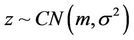 .
.  represents the
  -th element of vector
 .
.  represents the
  -th element of matrix
 .
.  means “Mod
 ”. The
  identity matrix is
 , and the
  all-zero matrix is
 .
.  and
and  denote the mean and the variance of
 , respectively.
2. OFDMA UL Signal Model
In OFDMA, each user is modulated by complex data symbols from a signal constellation, e.g., phase-shift keying (PSK) or quadrature amplitude modulation (QAM). In a frequency-selective fading channel, the received signal at the base station can be represented as
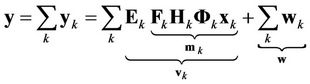 , (1)
, (1)
where 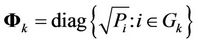 represents the power allocation to each subcarrier of user
 ,
,
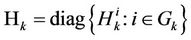
with  denoting the channel attenuation at the
  -th subcarrier, and
  stands for the subcarriers allocated to user
 . Note that
  and
and
 ,
,
 (2)
(2)
with  and
and  representing the initial phase and normalized frequency offset of user
 , respectively.
  denotes the Inverse Discrete Fourier Transform (IDFT) matrix for the
  -th user (where only the subcarriers allocated to user
  are modulated).
  is the Discrete Fourier Transform (DFT) length.
  is the transmit vector of user
 , and without loss of generality, we assume that
  are independent and identically distributed (i.i.d.) complex RVs with zero mean and unit variance.
  represents the time-domain transmit training of user
 ,
,  in (1) is a vector of additive white Gaussian noise (AWGN) with
 , and
, and  represents the additive noise added to user
 .
.
UL synchronization for each user can be performed based on the received training sequence . Without loss of generality, we assume that the frequency offsets of different users are i.i.d. RVs. For an OFDMA UL with
  users accessing a base station, the Fisher Information Matrix (FIM)
  is given by
 , (3)
, (3)
where  represents the northwestern
 sub-matrix of
 , and
, and  is a
is a  vector. The CRLB of user
  is given by
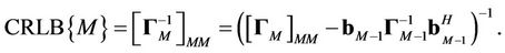 (4)
(4)
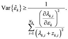
From Appendix I, for an unbiased estimator , the CRLB is derived as
 (5)
(5)
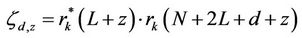
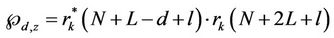
where  and
and  are defined as in Appendix I,
  ,
,  and
and  are constants specified by the structure of the training sequence used by user
  and
and  and
and  stand for the Signal-to-Noise-Ratio (SNR) and Signal-to-Interference-Ratio (SIR) of user
 , respectively. (5) suggests that MAI will degrade the estimation performance of the UL synchronization, and the MAI elimination/reduction is critical in increasing the frequency offset estimation accuracy.
3. Interference Analysis in OFDMA UL
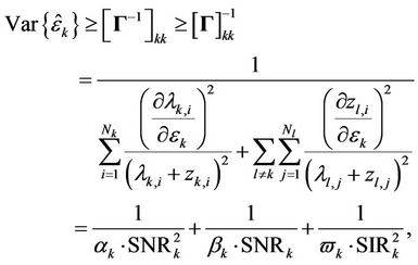
Note that in an OFDMA UL, the subcarrier groups allocated to different users are orthogonal, and this allocation eases the decomposing of the transmitted signal of each user. We consider two types of subcarrier allocation schemes: Block-based and Interleaved, as illustrated in Figures 1(a) and (b).
In an OFDMA UL, the receiver (base station) usually
Figure 1. Subcarrier allocation in OFDMA.
pre-demodulates the signal of each user, and only signals projected into the signal space of interest will be demodulated. Since the pre-demodulation improves the effective Signal-to-Interference-plus-Noise Ratio (SINR), an optimum CRLB for the  -th user is achieved as
 (6)
(6)
The pre-demodulation of each user’s signal can be performed as
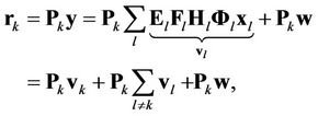 (7)
(7)
where 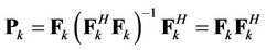 and
and  represents the interference from other users, i.e., MAI.
In order to analyze the MAI contributed by users other than user  (the user of interest), we first assume that
  users access the base station, and then we make some presuppositions:
1) 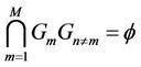 and
and where
where  represents the set of subcarriers allocated to user
 .
.
2) , where
  represents the cardinality of
 .
.
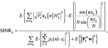
The average SINR of user  can be represented as
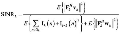 , (8)
, (8)
where
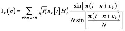
is the interference of the subcarrier  contributed by the other subcarriers of user
  (ICI), and
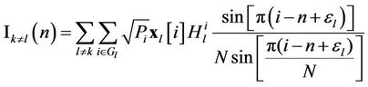
represents the interference of the subcarrier  contributed by the users other than
 .
.
When , the average SINR of user
  can be simplified as
 (9)
(9)
where  is a random variable (not necessarily Gaussian) with
 .
.
For a system with all the users running at the tracking phase (the frequency offset acquisition has been performed, and the remaining frequency offset is small), it is reasonable to assume that  for each
  is an i.i.d. RV uniformly distributed in
 , where
  [23]. The averaged SINR of user k can be further approximated as
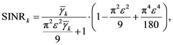 (10)
(10)
where 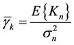 is used to represent the average received SNR of user
 .
.
The SINR reduction due to MAI is shown in Figure 2. A considerable MAI of one user will be contributed by the interfering users because of their non-zero frequency offsets. For example, when , the averaged SINR loss at the objective user may be up to 36.7%.
4. Heavy MAI Elimination
In Section 3, we analyzed the MAI introduced by interfering users. Since a new accessing user’s instantaneous frequency offset may contribute a heavy MAI to its neighbors, the base station should first perform UL synchronization for that user before its totally access. The accessing user will then correct its synchronization errors based on the feedback information from the base station.
In order to illustrate the distribution ofInter-CarrierInterference (ICI) with respect to the distance between the object subcarrier (subcarrier ) and the interfering subcarrier (subcarrier
 ), we define
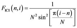
as the “ICI factor” between subcarriers  and
and , and we know that the ICI between subcarrier
  and
and  is proportional to
 . The upper figure in Figure 3 shows the distribution of
  as a function of
 , from which we know that the ICI factor diminishes as
  increases. The lower figure in Figure 3 illustrates the concentration of ICI energy, and it shows that most of the ICI energy added to one subcarrier is concentrated within a small range around the subcarrier. For a given ICI energy, the ratio of the concentration range to
  becomes smaller as
  increases.
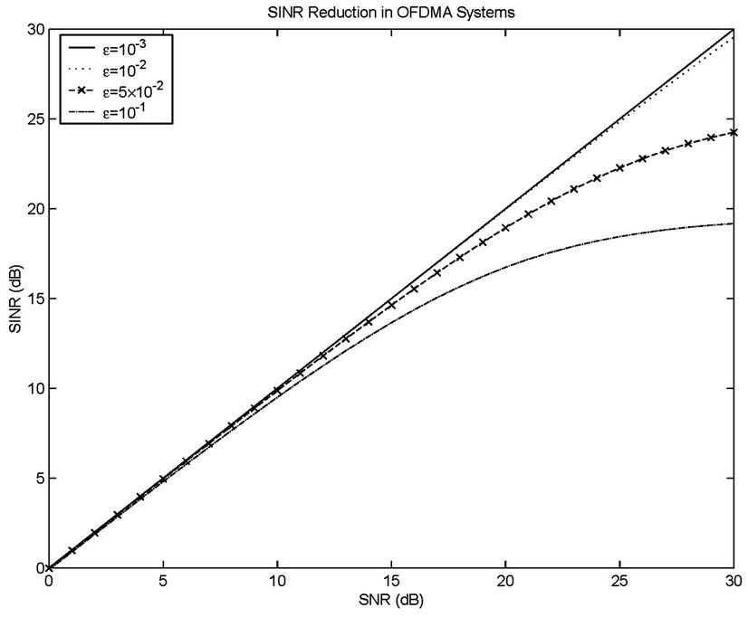
Figure 2. SINR reduction introduced by non-zero frequency offset in OFDMA systems.
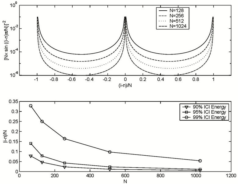
Figure 3. Inter-carrier-interference factors in OFDMA systems.
4.1. Heavy MAI Elimination in Block-Based Subcarrier Allocation Scheme
In the Block-based allocation scheme, user  is allocated a set of contiguous subcarriers, i.e.,
  , and its marginal subcarriers suffer most of the MAI. If we optimize
  of user
  to demodulate only its less-interfered subcarriers (the marginal subcarriers of heavy MAI are left un-demodulated, or in other method, we leave wide enough guard band between neighboring users), most of its MAI can be eliminated. Based on this princeple, we propose a method named the Reduced-RankProjector (RRP) method, i.e.,
 . In order to maximize the SINR of user k, we have
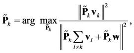 (11)
(11)
where .
.  here is defined as follows: without loss of generality, we first assume that the central frequency of
  is higher than that of
  and lower than that of
 . We also assume that user
  is interfered by user
  and user
  with its leftmost
  and right-most
  subcarriers, respectively.
  can be derived by deleting the left-most
  columns and the right-most
  columns from
 . Here, we also assume that the guard band between user
  and user
  is
is  subcarriers, and that between user
  and user
  is
is  subcarriers. Therefore,
and
 where
where  means the maximum integer part of
 , and
, and .
.
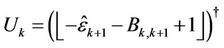
Figure 4 illustrates the frequency offset estimation with the help of the RRP method. Three frequency-domain neighbors, i.e., user , user
  and user
 , have instantaneously large frequency offsets. Since user
  suffers the highest MAI, we perform a synchronization for user
  and user
  first. At that time, the signals of user
  and user
  are demodulated by using projectors
  and
and , respectively. Using the estimation results
  and
and ,
,  and
and  can be derived to optimize
 . After that,
  is used to calculate
  and
and , and then
  and
and  are optimized. The optimized
  and
and  then can then be used to further improve the performance of
  and
and  1.
1.
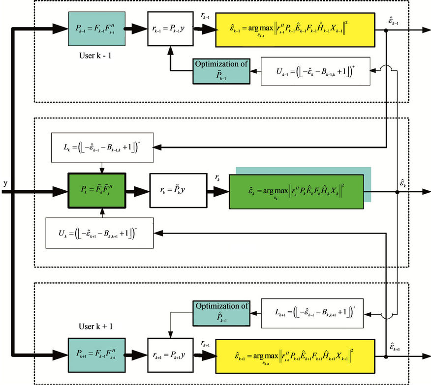
Figure 4. Interference elimination and frequency offset estimation in block-based subcarrier allocation scheme by using RRP method.
4.2. Heavy MAI Elimination in Interleaved Subcarrier Allocation Scheme
In Interleaved subcarrier allocation scheme (as illustrated in Figure 1(b)), there is no enough guard band to separate the different users, and the frequency offset immune capability will be degraded as a result. In this case, without loss of generality, we assume user  to be the user of interest and that user
  acts as an interfering user to it. We also assume that the frequency offset estimation result of user
  is
is , where
  and
and  represent the integer part and the fractional part of
 , respectively. Here, we assume that
  has already been corrected and that MAI is contributed only by
 . In order to eliminate this kind of MAI, we propose a method named the Shift-Sampling-Projector (SSP) method. We first perform the frequency offset estimation for user
  to obtain
 . The Shift-Sampling-Projector for user
  can be represented as
 where
where
and
 as illustrated in Figure 5. Note that
  in Figure 5 is given by (2) with
  being replaced by
 . If
. If  is accurate enough, the interference from user
  can be eliminated. The estimation result, i.e.,
  , then will be used to optimize
  in order to further increase the accuracy of
 . By using the SSP method, the variance error of
  will satisfy
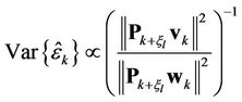 .
.
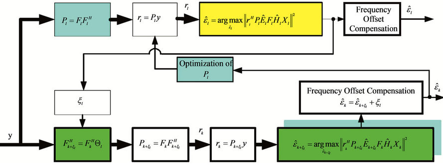
Figure 5. Interference elimination and frequency offset estimation in interleaved subcarrier allocation scheme by using SSP method.
5. Frequency Offset Estimation with MAI Reduction/Randomization
As mentioned earlier, instantaneously heavy MAI introduced by frequency-domain neighboring users should be eliminated before a user totally access the base station. In this section, we first discuss interference elimination by using the Successive Interference Cancellation (SIC) method, and then propose a frequency offset estimation algorithm based on an interference reduction scheme.
5.1. SIC with MAI Elimination
Let us assume that  users access a base station, and that
  are perfectly known at the receiver (base station). Based on the joint PDF of
  and
and , i.e.,
  , (as well as
 ) can be jointly estimated as
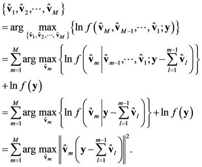 (12)
(12)
(16) provides a feasible way to estimate the signal/frequency offset of each user: the signals of different users can be estimated one by one based on . After performing a synchronization for the first
  users, user
  will estimate
  based on
 . In theory, if
  are accurate enough,
  can be estimated successfully2. However, if one previous user has a large estimation error, it will propagate to
 ; i.e., the estimation accuracy of
  depends on the estimation accuracy of
  v. For a large
 , estimation performance by using the SIC method will degrade because of the error propagation. Figure 6 shows the SIC-based frequency offset estimation performance. In this figure, a total of 16 users access a base station simultaneously. In order to reduce the error propagation in SIC, more than one iteration is required when performing MAI elimination, and the algorithm converges after 5 iterations.
5.2. RRTSG for MAI Randomization
The SIC-based method aforementioned requires both CSI and initial phase information, and in addition, more interfering users imply more iterations being required. Therefore, SIC is inefficient in a multiuser environment. Some differential algorithms that are independent of the initial phase and the wireless channel provide a new way for a solution [9,15]. In these differential algorithms, the training sequence contains repetition information, and the frequency offset can be estimated at the receiver by estimating the phase rotations between these repetitions. However, these conventional algorithms were originally proposed for DL synchronization, and they are not immune to MAI.
In this section, a new training sequence group named the Round-Robin Training Sequence Group (RRTSG) is proposed to perform OFDMA UL synchronization. A total of  training sequences are included in RRTSG, with each training sequence being composed of two
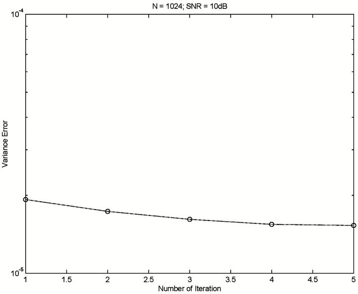
Figure 6. Frequency offset estimation with MAI elimination by using SIC.
training symbols, where the second symbol is generated by copying data from the first one (but at a different order). When generating the second training symbol of the  -th (
-th ( ) training sequence, we simply copy data from the already generated first symbol with its last $d$ samples shifted to the front. After padding each symbol with its corresponding CP, the
  -th training sequence is generated as:
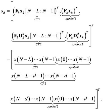 (13)
(13)
where  represents the CP length, and
is a pre-coding matrix for user  in generating the
  -th training sequence.
RRTSG can randomize MAI when performing UL synchronization, and an unbiased frequency offset estimator is always achieved, provided that each user is allocated a unique training sequence. A Best Linear Unbiased Estimator (BLUE) of  based on the
  -th training sequence is provided by:
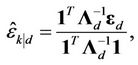 (14)
(14)
where
 ,
,  ,
,
 and
and  represents the
  element of
 . We can easily prove that the BLUE estimator provided by (18) is conditionally unbiased, and that its CRLB is found to be
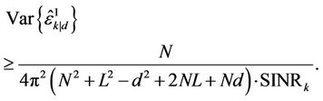 (15)
(15)
Among all the training sequences in the proposed RRTSG, the minimum CRLB is achieved when .
.
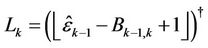
In order to make the estimator work properly,
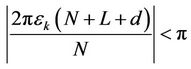
should be satisfied for each , and this requires the normalized frequency offset estimation range of the
  -th estimator to be limited within
 .
.
6. Numerical Results
In our simulation, an OFDMA UL transmission with a bandwidth of 10 MHz and DFT length of 1024 is considered. A length-64 cyclic-prefix is padded to the front of each symbol or training sequence. Wireless channel parameters are defined in Tables 1 and 2.
Figure 7 illustrates the performance improvement achieved in RRP by eliminating the instantaneously heavy MAI. In this simulation, we assume that 10 users access a base station simultaneously, and users #1, #2 and #3 are assumed to have instantaneously large frequency offsets. The frequency offsets for the other 6 users are assumed to have already been estimated and corrected, and their residual frequency offsets are assumed to be uniformly distributed within (–0.01, 0.01). This simulation parameters for users #1, #2 and #3 are presented in Table 1. User #2 is assumed to be the user of interest. The frequency offset estimation can be improved by using the RRP method. At low SNR, a variance error of less than  (or
(or ) can be obtained if we reduce the demodulated subcarrier range to [–22, 23] (or [–20, 21]).
Although the RRP method can achieve a considerable performance improvement with respect to MAI elimination, this method is not applicable in the Interleaved
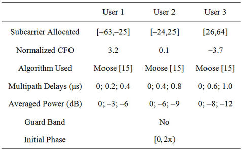
Table 1. Subcarrier allocation of heavy-interference users in block-based subcarrier allocation scheme (bandwidth = 10 MHz, DFT length = 1024, CP = 64).
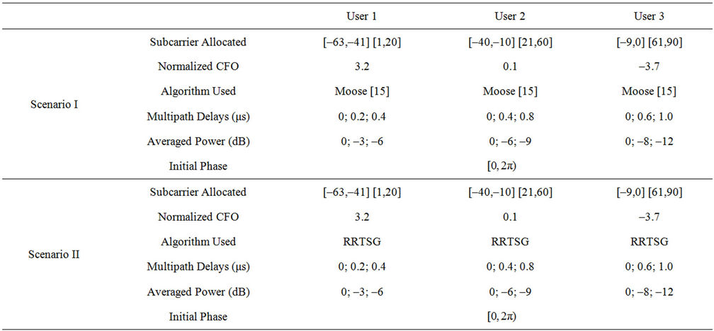
Table 2. Performance comparison between RRTSG-based scheme and Moose’s algorithm (bandwidth = 10 MHz, DFT length = 1024, CP = 64; No guard band between different users).
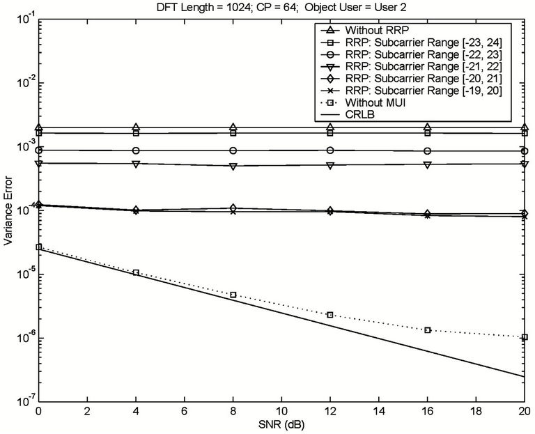
Figure 7. Frequency offset estimation with the help of heavy MAI elimination by using RRP.
subcarrier allocation scheme, which relies on the SSP method. Table 3 illustrates the parameters of this simulation. The simulation results are illustrated in Figure 8. Without using SSP, the variance error will always be higher than , no matter how high the SNR is. When the SSP method is applied, a considerable performance improvement can be obtained, even with imperfect frequency offset estimation in the interfering users. For example, at an SNR of 16dB, when the SSP method is applied with a 30% compensation error being assumed in the interfering user, a variance error smaller than
  can be obtained. The variance error can be further reduced to about
  if the compensation error is reduced to 20%.
When the number of accessing users is large, MAI elimination is impractical to perform. As a feasible MAI reduction scheme, MAI randomization is usually utilized. The proposed RRTSG has a high ability in performing MAI randomization in OFDMA UL transmission. Figure 9 illustrates the performance comparison between Moose’s algorithm and the proposed RRTSG-based algorithm. The simulated environment is defined by Table 2. The simulation results show that the proposed RRTSG-based algorithm outperforms Moose’s algorithm with respect to interference mitigation capability. Without using any heavy MAI elimination method (e.g., RRP or SSP), a biased frequency offset estimator is obtained by using Moose’s algorithm, so that its variance error is much larger than that of the proposed RRTSG-based algorithm. For example, a variance error of  can be achieved at a high SNR by using the proposed RRTSG-based algorithm, as compared to the variance error of
  obtained in Moose’s algorithm. The proposed MAI elimination methods proposed can improve the performance of both algorithms considerably. When most of the heavy MAI is eliminated by using RRP, e.g., the subcarriers ranging from
  & [26,55] are demodulated, a variance error of about
  is achieved by using the proposed RRTSG-based algorithm at an SNR
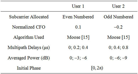
Table 3. Subcarrier allocation of heavy-interference users in interleaved subcarrier allocation scheme (bandwidth = 10 MHz, DFT length = 1024, CP = 64; no guard band between different users).
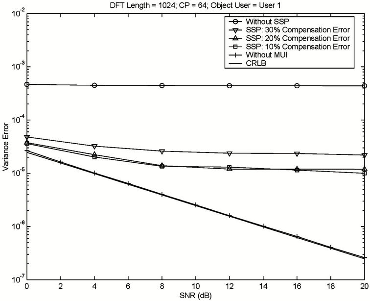
Figure 8. Frequency offset estimation with the help of heavy MAI elimination by using SSP.
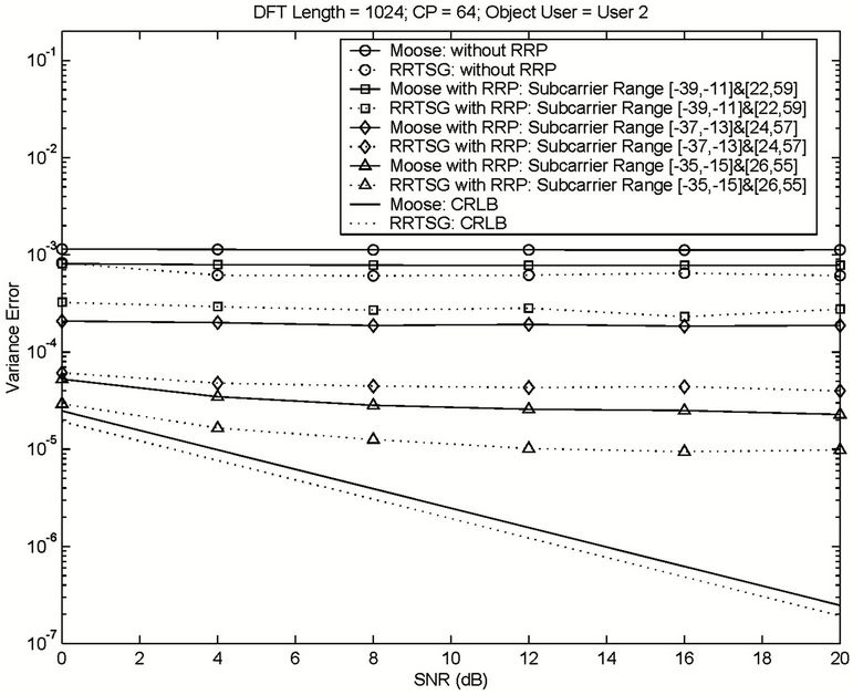
Figure 9. Performance comparison between Moose algorithm and the proposed RRTSG-based algorithm in heavy MAI environment.
of 15 dB. This error is still much smaller than that achieved by using Moose’s algorithm, i.e., .
.
7. Conclusion
This paper discussed OFDMA UL frequency offset estimation and showed that the performance improvement in estimation benefits from MAI elimination/reduction results in improved estimation accuracy. Two MAI elimination/reduction methods, i.e., the RRP method and the SSP method, were proposed for a Block-based subcarrier allocation scheme and interleaved subcarrier allocation scheme, respectively. In order to randomize the MAI contributed by the other synchronized users (because of their non-zero residual frequency offsets), a new training sequence group named the RRTSG was also proposed. Numerical results proved that the proposed RRTSGbased algorithm outperforms the conventional algorithm considerably in terms of frequency offset estimation accuracy because of its MAI randomization/mitigation capability.
REFERENCES
- S. Pietrzyk and G. Janssen, “Performance Evaluation of Bit Loading, Subcarrier Allocation, and Power Control Algorithms for Cellular OFDMA Systems,” International Conference on Personal Wireless Communications, Delft, Netherlands, 2004, pp. 349-363. doi:10.1007/978-3-540-30199-8_29
- I. Koffman and V. Roman, “Broadband Wireless Access Solutions Based on OFDM Access in IEEE 802.16,” IEEE Communications Magazine, Vol. 40, No. 4, 2002, pp. 96-103. doi:10.1109/35.995857
- L. Rugini and P. Banelli, “BER of OFDM Systems Impaired by Carrier Frequency Offset in Multipath Fading Channels,” IEEE Transactions on Wireless Communications, Vol. 4, No. 5, 2005, pp. 2279-2288. doi:10.1109/TWC.2005.853884
- Z. Zhang and C. Tellambura, “The Effect of Imperfect Carrier Frequency Offset Estimation on an OFDMA Uplink,” IEEE Transactions on Communications, Vol. 57, No. 4, 2009, pp. 1025-1030. doi:10.1109/TCOMM.2009.04.070246
- H.-C. Wu, “Analysis and Characterization of Intercarrier and Interblock Interferences for Wireless Mobile OFDM Systems,” IEEE Transactions on Broadcasting, Vol. 52, No. 2, 2006, pp. 203-210. doi:10.1109/TBC.2006.872989
- J. Zheng and Z. Wang, “ICI Analysis for FRFT-OFDM Systems to Frequency Offset in Time-Frequency Selective Fading Channels,” IEEE Communications Letters, Vol. 14, No. 10, 2010, pp. 888-890. doi:10.1109/LCOMM.2010.072910.100562
- Z. S. Zhang, C. Tellambura and R. Schober, “Improved OFDMA Uplink Transmission via Cooperative Relaying in the Presence of Frequency Offsets—Part I: Ergodic Information Rate Analysis,” European Transactions on Telecommunications, Vol. 21, No. 3, 2010, pp. 224-240.
- Z. Zhang, W. Zhang and C. Tellambura, “Improved OFDMA Uplink Transmission via Cooperative Relaying in the Presence of Frequency Offsets—Part II: Outage Information Rate Analysis,” European Transactions on Telecommunications, Vol. 21, No. 3, 2010, pp. 241-250.
- Z. Zhang, W. Jiang, H. Zhou, Y. Liu and J. Gao, “High Accuracy Frequency Offset Correction with Adjustable Acquisition Range in OFDM Systems,” IEEE Transactions on Wireless Communications, Vol. 4, No. 1, 2005, pp. 228-237. doi:10.1109/TWC.2004.840201
- H. Minn, V. Bhargava and K. Letaief, “A Robust Timing and Frequency Synchronization for OFDM Systems,” IEEE Transactions on Wireless Communications, Vol. 2, No. 4, 2003, pp. 822-839. doi:10.1109/TWC.2003.814346
- Z. Zhang, K. Long, M. Zhao and Y. Liu, “Joint Frame Synchronization and Frequency Offset Estimation in OFDM Systems,” IEEE Transactions on Broadcasting, Vol. 51, No. 3, 2005, pp. 389-394. doi:10.1109/TBC.2005.851702
- F. Gao, T. Cui and A. Nallanathan, “Scattered Pilots and Virtual Carriers Based Frequency Offset Tracking for OFDM Systems: Algorithms, Identifiability, and Performance Analysis,” IEEE Transactions on Wireless Communications, Vol. 56, No. 4, 2008, pp. 619-629.
- F. Gao and A. Nallanathan, “Blind Maximum Likelihood CFO Estimation for OFDM Systems via Polynomial Rooting,” IEEE Signal Processing Letters, Vol. 13, No. 2, 2006, pp. 73-76. doi:10.1109/LSP.2005.861583
- D. Huang and K. Letaief, “An Interference-Cancellation Scheme for Carrier Frequency Offsets Correction in OFDMA Systems,” IEEE Transactions on Communications, Vol. 53, No. 7, 2005, pp. 1155-1165. doi:10.1109/TCOMM.2005.851558
- P. Moose, “A Technique for Orthogonal Frequency Division Multiplexing Frequency Offset Correction,” IEEE Transactions on Communications, Vol. 42, No. 10, 1994, pp. 2908-2914. doi:10.1109/26.328961
- H. Lin and K. Yamashita, “Subcarrier Allocation Based Compensation for Carrier Frequency Offset and I/Q Imbalances in OFDM Systems,” IEEE Transactions on Wireless Communications, Vol. 8, No. 1, 2009, pp. 18-23. doi:10.1109/T-WC.2009.071007
- J.-J. van de Beek, P. Borjesson, M.-L. Boucheret, D. Landstrom, J. Arenas, P. Odling, C. Ostberg, M. Wahlqvist and S. Wilson, “A Time and Frequency Synchronization Scheme for Multiuser OFDM,” IEEE Journal on Selected Areas in Communications, Vol. 17, No. 11, 1999, pp. 1900-1914. doi:10.1109/49.806820
- S. Barbarossa, M. Pompili and G. Giannakis, “Channel-Independent Synchronization of Orthogonal Frequency Division Multiple Access Systems,” IEEE Journal on Selected Areas in Communications, Vol. 20, No. 2, 2002, pp. 474-486. doi:10.1109/49.983375
- H. Bolcskei, “Blind Estimation of Symbol Tming and Carrier Frequency Offset in Wireless OFDM Systems,” IEEE Transactions on Communications, Vol. 49, No. 6, 2001, pp. 988-999. doi:10.1109/26.930629
- Z. Cao, U. Tureli and Y.-D. Yao, “Deterministic Multiuser Carrier-Frequency Offset Estimation for Interleaved OFDMA Uplink,” IEEE Transactions on Communications, Vol. 52, No. 9, 2004, pp. 1585-1594. doi:10.1109/TCOMM.2004.833183
- M. Morelli, “Timing and Frequency Synchronization for the Uplink of an OFDMA System,” IEEE Transactions on Communications, Vol. 52, No. 2, 2004, pp. 296-306. doi:10.1109/TCOMM.2003.822699
- M.-O. Pun, M. Morelli and C.-C. Kuo, “Maximum-Likelihood Synchronization and Channel Estimation for OFDMA Uplink Transmissions,” IEEE Transactions on Communications, Vol. 54, No. 4, 2006, pp. 726-736. doi:10.1109/TCOMM.2006.873093
- Z. Zhang, W. Zhang and C. Tellambura, “Robust OFDMA Uplink Synchronization by Exploiting the Variance of Carrier Frequency Offsets,” IEEE Transactions on Vehicular Technology, Vol. 57, No. 5, 2008, pp. 3028-3039. doi:10.1109/TVT.2007.912596
- J. Zeng and H. Minn, “A Novel OFDMA Ranging Method Exploiting Multiuser Diversity,” IEEE Transactions on Communications, Vol. 58, No. 3, 2010, pp. 945- 955. doi:10.1109/TCOMM.2010.03.070473
- M. Movahhedian, Y. Ma and R. Tafazolli, “Blind CFO Estimation for Linearly Precoded OFDMA Uplink,” IEEE Transactions on Signal Processing, Vol. 58, No. 9, 2010, pp. 4698-4710. doi:10.1109/TSP.2010.2050063
- K. J. Kim, M.-O. Pun and R. A. Iltis, “Joint Carrier Frequency Offset and Channel Estimation for Uplink MIMOOFDMA Systems Using Parallel Schmidt Rao-Blackwellized Particle Filters,” IEEE Transactions on Communications, Vol. 58, No. 9, 2010, pp. 2697-2708. doi:10.1109/TCOMM.2010.080310.090053
Appendix
Derive the Fim
From [15], the  -th element of FIM
  can be represented as
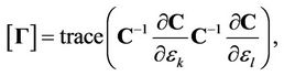 (16)
(16)
where 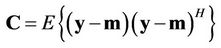 and
and 
Note that
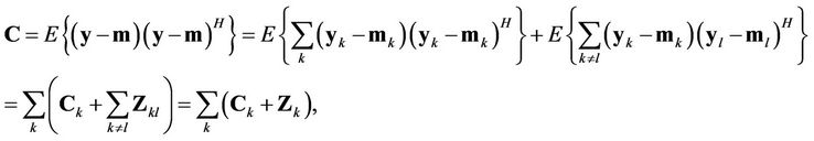 (17)
(17)
where
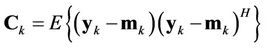
represents the covariance matrix of user , and
, and
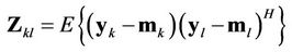
is the MAI matrix of user  contributed by user
 . For the non-zero frequency offsets, we have
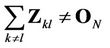 .
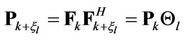
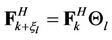
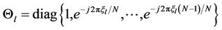
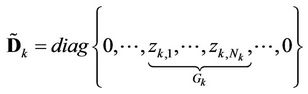
.  is decomposed as
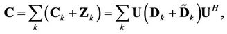 (18)
(18)
where  is a
is a  Unitary matrix,
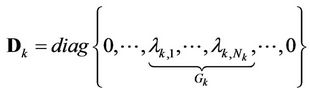
with  representing the
  -th eigenvalue of
 , and
, and
with  representing the
  -th eigenvalue of
 . Therefore, we also have
 (19)
(19)
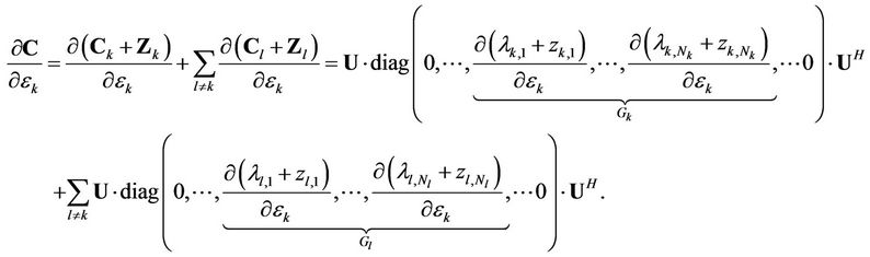
From the above discussion,
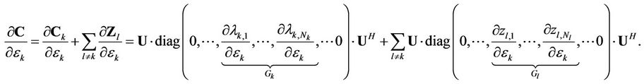 (20)
(20)
when , the
, the  -th element in FIM can be represented as
 (21)
(21)
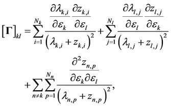
and the  -th element in FIM is given by
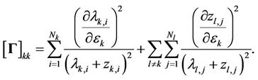 (22)
(22)
NOTES
*This work was supported by the National Basic Research Program of China (2012CB315905), the National Natural Science Foundation of China under Grand No. 61172050, National Key Projects (2012ZX 03001029-005 and 2012ZX03001032-003), Beijing Science and Technology Program under Grand No. 2009ZX03006-004, Chang Jiang Scholars Program of the Ministry of Education of China, and Program for New Century Excellent Talents in University.
#Corresponding author.
1This kind of operation can be applied in the scenario of multiple users transmitting and receiving jointly, e.g., multiuser Multiple-Input Multiple-Output (MIMO).
2SIC algorithm requires a knowledge of channel state information (CSI) at the base station, and the CSI information can be obtained through channel estimation (please refer to, e.g., [26]), which is beyond the scope of this paper.