Communications and Network
Vol.3 No.4(2011), Article ID:8472,9 pages DOI:10.4236/cn.2011.34024
Investigation of Upstream Near-Far Problem in VDSL Systems via Complete Adaptive Iterative Water Filling Algorithm
Communication Engineering, Islamic Azad University of Tehran South Branch, Tehran, Iran
E-mail: sadeghi.m@hotmail.com
Received September 20, 2011; revised October 25, 2011; accepted November 3, 2011
Keywords: Dynamic Spectrum Management, Very-High Bit-Rate Digital Subscriber Line (VDSL), Near-Far Problem, Iterative Water-Filling
Abstract
Crosstalk is the main degrading factor in Digital Subscriber Line (DSL) systems which are the result of electromagnetic coupling between two adjacent twisted pairs in a cable. Very-high bit-rate Digital Subscriber Line (VDSL) systems which use higher frequencies for data transmission than the other DSL systems, this effect is more considerable in Bit Error Rate (BER) degradation. This paper considers a complete adaptive iterative water-filling (IWF) algorithm for Resolving Upstream Near-Far Problem in VDSL Systems. The new distributed dynamic spectrum management algorithm is proposed, which improve achievable bit rate of iterative water-filling algorithm. The paper proffers a new power back-off strategy of the spectral mask at the near-end users, in order to protect the far-end users. Simulation of the proposed algorithm indicates that the bit rate is increased considerably rather the IWF and adaptive water-filling (AIWF) algorithms by keeping their low complexity. Furthermore, by adding the number of users in network, the new algorithm achieves performance gains over the AIWF, completely adaptive.
1. Introduction
The most popular broadband access technology is the DSL [1]. In the performance of DSL systems, the most important factor is the interference between cables, known as crosstalk. Crosstalk can seriously limit the performance of the system if it is not dealt with. The DSL channel is highly frequency-selective and at high frequency the crosstalk is very significant, generally. For instance, in upstream near-far problem of VDSL, the crosstalk from the near-end (strong) users can has impact on the signaling of the far-end (weak) users, particularly at high frequency band, and significantly decline the far-end user’s data rate. In order to use the higher frequency bands, effective spectrum management techniques must be used.
The Static Spectrum Management (SSM) is most basic form of spectrum management [2]. SSM applies identical spectral masks based on a worst-case scenario assumption for all users where all the possible users in a cable binder are active [2,3]. Based on this assumption, the interference plus noise term for each user is static, means it does not change.
In actuality, there are many splices, bridge-taps, and other cable imperfections, which make the SSM worstcase model even more inexact. As well, in practice, the number of active users changes constantly and therefore in order to make effective use of the spectrum, in order to maximize the achievable bit-rate it is essential to dynamically allocate transmit PSDs. Therefore, this led to the introduction of Dynamic Spectrum Management (DSM) [3,4].
Generally, two main implementation approaches exist in DSM: distributed and centralized. Each one has its own advantages and drawbacks. Centralized systems require a central hub with full knowledge of the network. Generally, this system allows for better performance at a cost of rising the computational time and the complexity. On the other side, distributed systems permit for every user to optimize itself. Alternately, distributed systems decrease the complexity and computational time but often lose some optimality in terms of performance. Correspondingly, the suboptimal DSM algorithms possess low-complexity and distributed implementation characteristics but they have sub-optimal problem.
One of the first distributed DSM techniques, IWF [5], enjoys a fully distributed and autonomous implementation with a reasonably low computational complexity. However, it is well known that the performance of IWF is sub-optimal, too. The sub-optimality of IWF is caused by inefficient use of the frequency spectrum. In an attempt to increase the efficiency of the frequency spectrum, many other heuristic variations were proposed. Interested readers are referred to [6-11]. One of the algorithms which improve on the performance of IWF is adaptive IWF [11]. This algorithm showed that in the upstream VDSL scenario, if the FEXT was impacted by one near-end user from central office, influenced on farend users, and then AWIF algorithm only decreased power of sub-channels that influenced on bit rate of farend users, instead of total transmission power of nearend user.
Inspired by this theory, in this paper, a complete adaptive IWF algorithm is proposed to resolve the near-far problem. It is known that the coupling and channel gains in DSL systems which are severely Frequency-Selective. Therefore, by this fact, the proposed algorithm decreases the transmission power of near-end users only in subchannels that have the worst effect over bit rates of far-end users, completely adaptive. Simulation results show that the proposed CAIWF algorithm improves the performance of the IWF and AIWF algorithms considerably, and can approach the optimal performance, that not possible by the AIWF algorithm for more users. Furthermore, CAIWF also retains all advantages of IWF and AIWF, i.e., fully-distributed implementation, low-complexity.
2. System Model
The DSL environment is a multiuser environment, therefore the background noise in the loop is typically small and the system performance is limited by crosstalk. A DSL channel with multiple users it shown as an interference channel, e.g. Figure 1.
By attention to this theory, consider a DSL network with a set of users (modems) 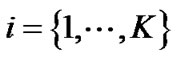 and a set of tones (frequency carriers)
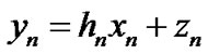
 . Using synchronous Discrete Multi-Tone (DMT) modulation, there is no Inter-Channel Interference (ICI) and transmissions can be modeled independently on each tone n as follows:
 (1)
(1)
The vector 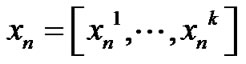 contains the transmitted signals for all users on frequency tone n, where
  is
is
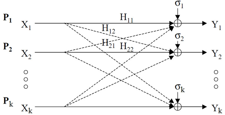
Figure 1. A gaussian interference network.
the transmitted signal by user i on frequency tone n. Similarly, 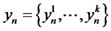 and
and  where
where  is the received signal for user i on frequency tone n. Likewise,
  is the additive noise for user i on frequency tone n which contains thermal noise, alien crosstalk and radio frequency interference.
  is an K × K matrix such that
  is the channel gain from transmitter j to receiver i on frequency tone n, and is defined as
 . Suppose the transmitted PSD of user i on frequency tone n is defined by
 where
where  denotes expected value, and Δf = 4.3125 denotes the frequency tone spacing. The vector containing the PSD of user i on all frequency tones is defined as
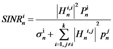
 . Therefore, the signal-to-interferenceplus-noise ratio (SINR) of user i on frequency tone n is expressed as:
 (2)
(2)
where 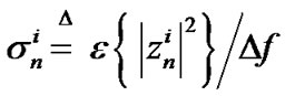 is the noise power density of user i on frequency tone n. When the number of users is large enough, the interference is well approximated by a Gaussian distributed random variable, and hence the achievable bit rate of user i on frequency tone n is defined as:
 (3)
(3)
where G is the Signal to Noise Ratio (SNR) gap which is a function of the desired coding gain, BER, and noise margin [12]. Then the achievable data rate for user n is:
 (4)
(4)
Where 0 £ ¦s £ Fs, Fs = 1/Ts, and Ts is the sampling rate. There are several physical limitations were taken advantage of the transmit powers for each user. One such limitation is the maximum power which each user is allowed to allocate over all of its frequency tones. The maximum power limitation for user i is denoted by . Another limitation is the maximum power which each user is allowed to allocate on any particular frequency tone referred to as a spectral mask. The spectral mask for user i on frequency tone n is mentioned by
 . Therefore, the power limitation can be summarized as:
 and
and 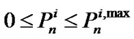 (5)
(5)
Now, optimization problem for dynamic spectrum management on maximizing the achievable data rate of one particular user (e.g., user 1) in DSL system can be shown as:
 (6)
(6)
where  is target rate for user i, and i > 1.
3. Near-Far Problem
Figure 2 shows an example of two phone lines (loops) coming out from a central office or optical network unit (CO/ONU) in the same binder group. This type of formation is known as a distributed topology because the near-end and far-end loop lengths differ in a substantial manner. When all lines support VDSL or the spectra of services other than VDSL in the binder do not overlap the frequency bands used by VDSL, and then the performance on each loop, both downstream and upstream, is limited by FEXT from other VDSL lines.
At any distance from CO/ONU to the customer premises (CP) the downstream signal levels on all lines are approximately equal when all transceivers at the CO/ ONU transmit at the same PSD. As a result, in the downstream direction at any distance from the CO/ONU on

Figure 2. A near-far VDSL scenario example.
the loops, FEXT contributions between lines in the binder are approximately reciprocal.
In contrast, if all transmit PSDs in the upstream direction be identical, signals on near-end lines will detrimentally affect upstream performance on far-end lines from central office. For example, suppose all upstream transmitters send signals at the maximum VDSL transmit PSD. According to Figure 2, Due to coupling into far line, the signal transmitted from the #CP2 on far line will be attenuated, probably significantly, by the #CP1 on near line. If the transmit PSD of the #CP1 on near line, be at the maximum level, it is remarkably higher than the attenuated level of the desired signal on far line. The result of the (relatively) high-power FEXT received by far-end lines from central office, is a degradation in achievable upstream rate. Clearly, in this formation the level of FEXT at the upstream receiver is not the same from line to line due to the variability of where, relative to other transmitters, signals first couple into other lines in the binder.
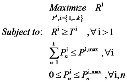
In the Figure 3, you can see that the achievable bit rate in the upstream direction is a function of range with two assumptions about the loop topology. In both cases, there are 10 active VDSL loops. One is the loop of interest, and the other nine are disturbers. The solid curve shows the achievable upstream bit rates when the topology in Figure 2 is assumed with the loops varying in length from 150 m to 1500 m in increments of 150 m. The dashed curve illustrates upstream bit rates that can be achieved if all the lines are the same length (given by the x-axis of the plot) and all #CPs transmit at a PSD level of –60 dBm/Hz at all frequencies from 138 kHz to 12 MHz. An additive white Gaussian noise (AWGN) floor of –140 dBm/Hz is assumed. Under these conditions, the
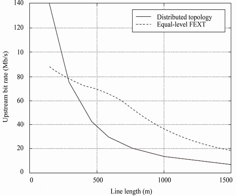
Figure 3. The impact of the near-far effect on upstream VDSL bit rates.
FEXT levels received by all CO/ONU are the same. In this case, all #CPs transmits upstream at –60 dBm/Hz at all frequencies from 138 kHz to 12 MHz, and an AWGN floor of –140 dBm/Hz is presumed.
Figure 3 illustrates the considerable, usually detrimental effect on upstream bit rates when all #CPs are allowed to transmit at the same PSD level and the loop lengths vary. On many loops if all lines were the same length, the achievable rates are less than half what they would have been. For this reason, when #CPs are allowed to transmit at the maximum PSD, a spectral compatibility problem between VDSL lines results. To resolve this problem, which is often referred to as the near-far problem, upstream transmitters on near-end lines must decrease their transmit PSDs such that they do not compromise the upstream bit rates in unfair manner, that can be adapted over the far-end loops from CO/ONU. The process of decreasing the upstream transmit PSD to improve spectral compatibility between VDSL lines of different lengths is known as upstream power back-off (UPBO).
Several methods have been proposed for UPBO in Static Spectrum Management (SSM) and Dynamic Spectrum Management (DSM). Interested readers on UPBO in the SSM methods for VDSL can refer to [13] and [14].
Also, for UPBO in DSM, there is an algorithm which named IWF power control algorithm. IWF is the best ever known DSM distributed power control solution for near-far VDSL problems, but the performance is suboptimal than the other DSM techniques. Therefore in the next sections, a brief review of IWF algorithm will be explained and then a new complete adaptive IWF algorithm will be proposed for maximizing the achievable bit rate of IWF for resolving sub-optimal problem, with retaining all the advantages.
4. IWF Algorithm
The IWF algorithm in an iterative manner performs water-filling one user at a time. Until reaching a Nash Equilibrium (NE) point, users perform water-filling in turn continuously. NE is a point where no user can benefit from changing its power allocation. When applying rate limitations, each user adjusts their water-filling process to ensure that they achieve their target rate. When applying water-filling, if a user achieves a rate higher than its target rate, that user’s allowable total power is decreased; In the same way, if a user achieves a rate lower than its target rate, that user’s allowable total power is increased. The allowable total power can never be more than the total power limitation. Therefore, the target rate set for the users must be attainable target rates for active users for the algorithm to converge. This process is as follows:
Algorithm 1: Iterative Water-Filling Algorithm
Consider a K-user interference channel where each user has a power constraint P. Let Ti be the target rate for user i.
5. The AIWF Algorithm
In the adaptive IWF algorithm, by pro-actively setting the spectral mask at each user, the game played by the users during the IWF process is effectively changed. Then, the new resulting NE point is expected to be different from the NE point obtained by IWF with total power constraints only. This process is as follows:
Algorithm 2: Adaptive Iterative Water-Filling Algorithm
Initially, all the users perform water-filling simultaneously with their maximum total power under the assumption of no interference. Each user then measures the interference levels it experiences in all the frequency bands, then divides its frequency bands into 3 regions (as: ,
,  and
and ). All the users then play the IWF game with their maximum total power to determine the PSD
  at the NE, and use it as the reference spectral mask. The AIWF algorithm can be implemented in a two-stage looping procedure. The first stage performs IWF while regarding the interferences caused by other users as noise until a convergence criterion is reached, i.e., the NE is obtained. The difference here is the power spectral mask applied at each user. The second stage finds the appropriate power spectral masks for each user. If its obtained data rate (Ri) is higher than its target rate (Ti), user-i starts to back off its power in the region
  by a factor of δ = 2 with
  as the initial reference spectral mask.
If the spectral mask in band  is too small (less than a threshold
 ), user-i proceeds to back off its power in region
 . If its obtained data rate is close to or smaller than its target rate, user-i keeps its spectral mask unchanged.
For more information, see [11].
6. The Proposed Algorithm
The important idea of complete IWF is proposed, based on interference learning status of each user. This algorithm allows the near-end users to decrease their transmission power only for special frequency bands. Considering the limited transmission power at each sub-channel, transmitted bit rate is primarily analyzed as:

This optimization problem is solved using a waterfilling process as in:
 (8)
(8)
where,  is the water-filling area, which can be adjusted to meet the sum power constraint, and
 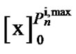 is the Euclidean distance of the variable x from the point [0,
 ].
].
To regulate the spectral power mask at one user we need to know about the allocated power in each subchannel by other users. This requires some information exchange between users. To avoid crosstalk between users and retaining the user’s independency in a VDSL network, users should have the learning ability. Namely, each user should learn the amount of interference in each bandwidth and then regulate the power mask, accordingly. This way, the crosstalk of users would be reduced. Firstly, each user will assume that there is no ICI perform the water-filling process. Then, each user evaluates the interference in each sub-channel. If the calculated interference in one sub-channel is high, then the user concludes that other users implementing a large amount of power to send information within this sub-channel. Hence, the ith user should classify the bandwidth into three regions. These are; the high-frequency interference region, Ai, the low-frequency interference area, Bi, and the very low-frequency interference region, Ci. Here, to protect the data transmitted rate for other users, the ith user has to reduce the allocated power for sending information in the high-frequency interference sub-channels (using the spectral mask). If the ith user identifies that other users hardly use the Ci region, there would be no more need to mask the power within sub-channels of Ci regions and allows the power allocated by water-filling process to this sub-channels. In DSL area, because of low weakening characteristics at lower frequencies, the water-filling process will consider more sub-channels to be transmitted to sub-channels with lower frequency. Therefore, the users are more eager to send data at lower frequencies. Based on this, in the proposed algorithm the domain of each region will change adaptively, according to the data rate and target rate of each user. This means, if the data rate of a user exceeds the target rate, the Ai region would be wider. Thereby, to decrease the data transmitting rate, a larger power portion of this area would be reduced by dividing to d (assume d = 2). This way, the user optimization will converge sooner. Besides, if the data transmitted rate is still more than the target rate, the Ai region will be estimated again, and the region’s power will be divided by d, too. On the other hand, if the power in Ai region came less than a threshold value, τ (τ is a control parameter), but the data transmitted rate is still more than the target rate; the power value of this region will be set to zero. However, if even after this, the data transmitted rate is still exceeds the target rate the amount of power in Bi region will be divided by d and the procedure will be repeated for Bi region similarly.
More clearly, process of CAIWF algorithm is as follows:
Power spectrum in low frequencies causes that users tend to transmit data in the lower frequency regions in VDSL network. Subsequently by increasing the number of users, the impact of FEXT crosstalk caused by low frequencies in near-end users over far-end users from central office will be increased. For this reason, CAIWF algorithm separates frequency band to different frequency band regions, according to impact of crosstalk value over other users. This algorithm executes two steps. In first step the water-filling action will be applied over each user, the interference plus noise value,  , power spectrum mask and border of each specified region will be determined that this frequency regions change according to bit rate and target rate
 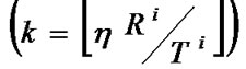 of each user and interference impact of each subchannel over bit rate of other users, after every water-filling execution over users, adaptively. In next step, after estimation of frequency regions and determination of bit rate of each user, the action of spectrum management will be done over each frequency region and subchannel power of each region will be compared according to spectrum mask that specified in first step. If bit rate of first region be higher than target rate, then spectrum power of related region will be compare with a threshold level, τ, (by this assumption, τ = 0.01). After that, if it is higher than τ, the related power of that region will be divided by δ. This process continues until the maximum power equal to specified spectrum mask. This process repeat until each specified adaptive frequency region reach to a spectrum balance point. Therefore each user reaches an optimized bit rate, finally.
This algorithm is summarized in the following:
Algorithm 3: Complete Adaptive Iterative Water-Filling Algorithm
Initial play: each user water-fills in the assumed absence of crosstalk.
Determine the frequency regions Ai, Bi, and Ci, ∀i.
If user ith have data rate Ri and target rate Ti, then
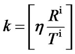 . The parameter η is variable.
Frequency regions for Ai is [3.75 MHz, 3.75 MHz + k*Δf]
Perform IWF to find , and use it as the reference spectral mask.
Initialize δ > 0, e > 0, τ > 0,  , ∀i, ∀n.
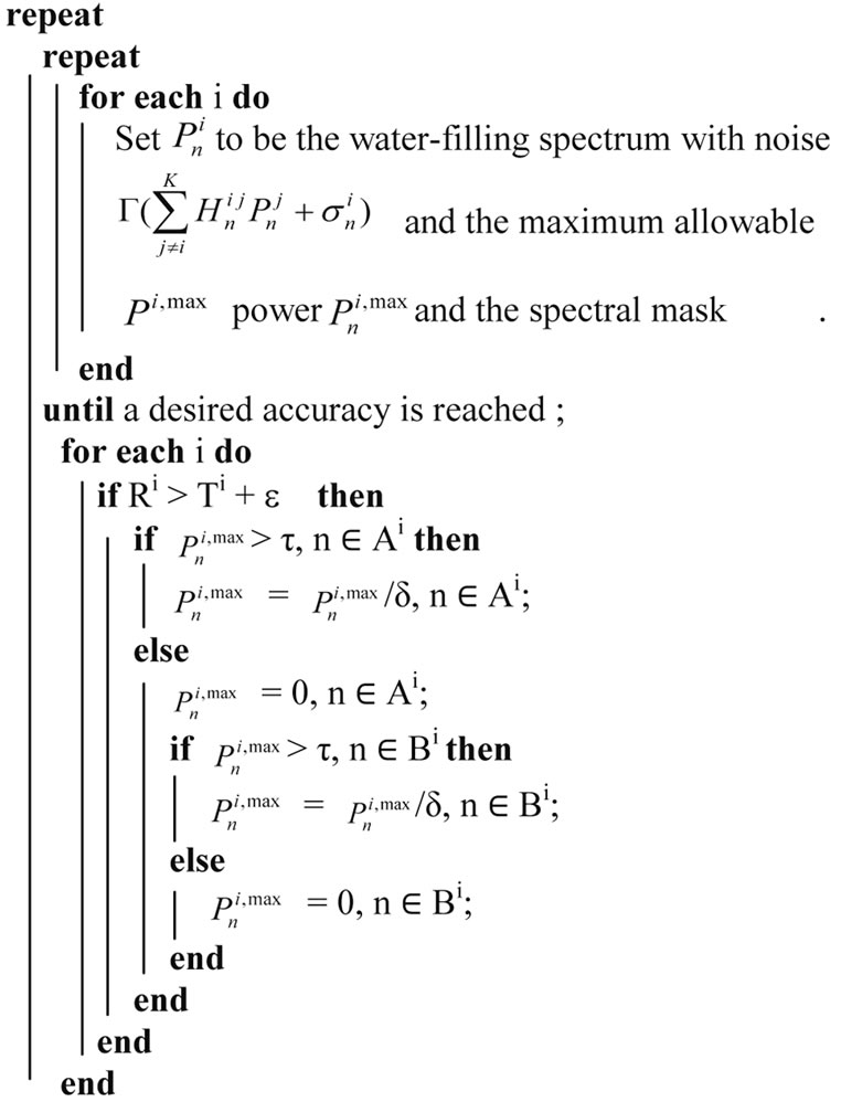
until Ri > Ti for all i;
k is a parameter that determine border of each region, η is a control parameter that in simulations is assumed 300, and reference spectrum mask is variable that after each water-filling execution can be determined according to .
.
The algorithm is found to work well with parameters d = 2 (3 dB) and e equal to roughly 10% of the target rate.
7. Complexity
Another significant factor in choosing a one algorithm is the implementation time (or run-time). The implementation time algorithm depends on many factors including the programming language used, the coding used, the processor(s) used, etc. For this reason, the performance metric used in this section will be computational complexity. Computational complexity denotes the number of operations required for the execution of an algorithm. More specifically, it shows the behavior one algorithm as the input sizes ascend. For showing this,  (.) notation is used. It describes the limiting behavior of a function when the arguments tend towards limitlessness. This is described mathematically as follows:

where  is some constant.
There are two main variables of interest in the representing complexity: the number of users, N, and the number of frequency tones, K. Hence, all algorithms will be of the form 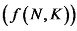
 for some function
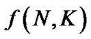 .
.
7.1. IWF Complexity
In IWF algorithm, the total interference plus noise is measured locally by each user. Therefore, implementation time is completely autonomous in this algorithm.
IWF is composed of two loops where the outer loop cycles through the inner loop for all users. The inner loop performs water-filling for the K-th user over all the N frequency tones. The water-filling process involves a bisection search for finding water-filling level of the users; Assuming that the number of bisection iterations required for the PSD to converge and the number of iterations required for the IWF to converge are v1 and v2, respectively. The total complexity of the IWF algorithm will be v1 ´ v2 ´ K ´ N, which implies:
 (NK) (10)
7.2. AIWF Complexity
The differences between AIWF and IWF methods is in determining NE point and spectrum mask value in each user, which have no impact in determination of algorithm complexity, therefore like IWF algorithm complexity, complexity of AIWF algorithm is equal to  (NK).
(NK).
7.3. CAIWF Complexity
In CAIWF method, first a learning process is performed to determine the Ai, Bi and Ci regions. This stage will not increase the method’s complexity, and the rest of the algorithm is similar to IWF process. Therefore, the complexity level of CAIWF method is the same as IWF, namely,  (NK).
(NK).
8. Simulation Result
In the VDSL scenario, you should focus on upstream transmission as shown in Figure 2, with the simulation parameters taken from [11].
Figure 4 illustrates the achieved upstream rate regions by the power control algorithm based on the IWF [5], AIWF [11] and proposed CAIWF for 2 VDSL loops, 0.9 Km versus 0.45 Km. As can be seen, The AIWF and the CAIWF algorithms support bigger achievable rate regions than the IWF algorithm does. Assume that a service of 8 Mbps is demanded on the 0.9 Km loop. Using the AIWF algorithm instead of the IWF algorithm allows the data rate on the 0.45 Km loop to be ascended from 38 Mbps to 51 Mbps, which according to a gain of 34.2%. Using the CAIWF algorithm allows further gain to be achieved, increasing the data rate of the 0.45 Km loop to 51.5 Mbps. This corresponds to a gain of 33.5%.
The second VDSL upstream scenario shown in Figure 5, consist of four user with the different line lengths 1.2 Km, 0.9 Km, 0.6 Km and 0.3 Km, respectively. If you Consider bit rate on the 0.6 Km loop than the 0.3 Km loop, then the proposed CAIWF algorithm supports larger achievable rate regions than the IWF and AIWF algorithms. Assume that a service of 30 Mbps is required on the 0.6 Km loop. Using the AIWF algorithm instead of the IWF algorithm allows the gain on the 0.3 Km loop to be increased Up to 16.8%, but using the CAIWF algorithm allows further gain to be achieved, Up to 29.2%.
In addition, at the Figure 6, an 8 users scenario is considered, where 4 users are located at 0.9 Km and the other 4 users are located at 0.45 Km from the CO. Similar the 2 users and 4 users scenarios, the proposed algorithm is achieved to the higher bit rate than IWF and AIWF algorithms.
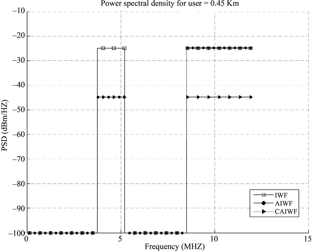
Figure 7 depicts the power spectral densities. Considering this figure, it indicates that because of lower channel attenuation of lower frequencies, all users prefer to choose a low frequency transmitting signals. So, in lower frequencies crosstalk would be increased. Therefore, the CAIWF algorithm employs this fact and reduces the power spectrum density of the lower distance lines (0.45 Km), considering the crosstalk rate among the lower frequencies, and instead allocate the remaining power spectrum density to the lines with longer distances (0.9 Km).
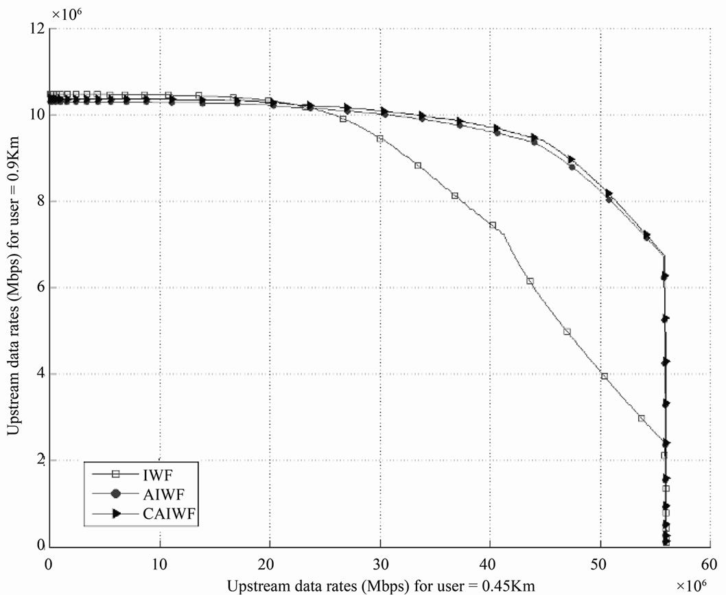
Figure 4. Rate regions of IWF, AIWF and CAIWF algorithms for 2-user VDSL upstream scenario.

Figure 5. Rate regions of IWF, AIWF and CAIWF algorithms for 4-user VDSL upstream scenario.
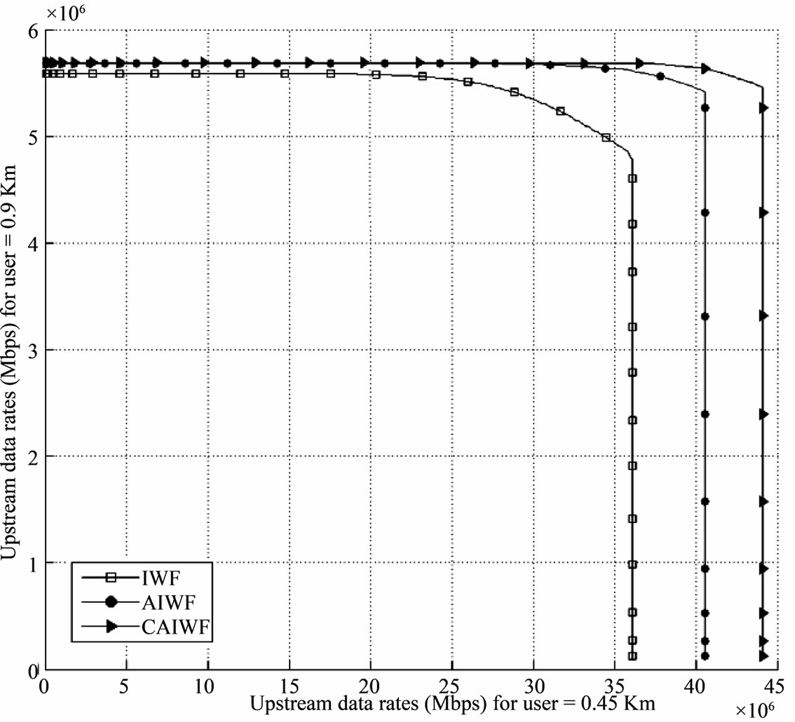
Figure 6. Rate regions of IWF, AIWF and CAIWF.
 (a)
(a) (b)
(b)
Figure 7. Power allocations for 8-user VDSL upstream scenario. (a) 0.45 km loop; (b) 0.9 km loop.
9. Conclusions
In this paper, the power control algorithm is implemented, which is completely adaptive. This method is called Complete Adaptive IWF (CAIWF). Using this method, the far-near problem is solved and an optimum performance ability for more users in VDSL systems is obtained. Instead of reducing the total power of near-end users to increase the bit rate of the far-end users, an algorithm is proposed that reduces the transmitted power only in the bands with high-frequency interference and assigns the remaining power to other bands using the water-filling algorithm. In simple words, the proposed algorithm divides the bandwidths to the different frequency band regions and according to the crosstalk value at the far-end users within these bands, adaptively changes the boundary of frequency regions in which the allocated power should be decreased within those sub-channels (considering the data transmitted rate and target rate). Therefore, implementing this method a higher bit rate is obtained (compared to the similar algorithms). Interestingly, this algorithm also could be performed in a completely distributed manner with a same complexity as the IWF and AIWF algorithms.
10. References
[1] Broadband Forum, “3 Million New North-American Broadband Subscribers Added in First Quarter 2009 Despite Economic Downturn,” News Release, 2009, pp. 1-3.
[2] ANSI Standard T1.417-2001, “Spectrum Management for Loop Transmission Systems,” Prepared by the ANSI T1E1.4 Working Group on Digital Subscriber Line Access, American National Standard, 2001.
[3] T. Starr, M. Sorbara, J. M. Cioffi and P. J. Silverman, “DSL Advances,” Prentice-Hall, Upper Saddle River, 2003.
[4] J. M. Cioffi, S. Jagannathan, W. Lee, H. Zou, A. Chowdhery, W. Rhee, G. Ginis and P. Silverman, “Greener Copper with Dynamic Spectrum Management,” Proceedings of IEEE Global Communications Conference, New Orleans, December 2008, pp. 1-5. doi:10.1109/GLOCOM.2008.ECP.1092
[5] Y. Wei, G. Ginis and J. M. Cioffi, “Distributed Multiuser Power Control for Digital Subscriber Lines,” IEEE Journal on Selected Areas in Communications, Vol. 20, No. 5, 2002, pp. 1105-1115. doi:10.1109/JSAC.2002.1007390
[6] Y. Liu and Z. Su, “Distributed Dynamic Spectrum Management for Digital Subscriber Lines,” IEICE Transactions on Communications, vol. E90B, No. 3, 2007, pp. 491-498.
[7] H. Bagheri, M. R. Pakravan and B. H. Khalaj, “Iterative Multi-User Power Allocation: Performance Evaluation & Modification,” Proceedings of IEEE Region 10 TENCON, vol. 3, 2004, pp. 216-219.
[8] D. Statovci, T. NordstrÄom and R. Nilsson, “The Normalized-Rate Iterative Algorithm: Apractical Dynamic Spectrum Management Method for DSL,” EURASIP Journal on Applied Signal Processing, Vol. 2006, 2006, Article ID: 95175. doi:10.1155/ASP/2006/95175
[9] W. Lee, Y. Kim, M. H. Brady and J. M. Cioffi, “BandPreference Dynamic Spectrum Management in a DSL Environment,” GLOBECOM, 27 November-1 December 2006, pp. 1-5. doi:10.1109/GLOCOM.2006.585
[10] Y. Noam and A. Leshem, “Iterative Power Pricing for Distributed Spectrum Coordination in DSL,” IEEE Transactions on Communications, Vol. 57, No. 4, 2009, pp. 948- 953. doi:10.1109/TCOMM.2009.4814362
[11] D. H. N. Nguyen and T. Le-Ngoc, “Adaptive Iterative Water-Filling for Dynamic Spectrum Management in DSL Networks,” 2010 IEEE International Conference on Communications (ICC), Cape Town, 23-27 May 2010, pp. 1-5. doi:10.1109/ICC.2010.5502366
[12] T. Starr, J. M. Cioffi and P. Silverman, “Understanding Digital Subscriber Line Technology,” Prentice-Hall, Upper Saddle River, 1999.
[13] FSAN VDSL Working Group, “Power Back-off Methods for VDSL,” ETSI TM6 Contribution 983t17a0, Luleå, June 1998, pp. 1-6.
[14] K. S. Jacobsen, “Methods of Upstream Power Back off on Very High Speed Digital Subscriber Lines,” IEEE Communications Magazine, Vol. 39, No. 3, 2001, pp. 210-216. doi:10.1109/35.910609