World Journal of Mechanics
Vol.3 No.9(2013), Article ID:40589,11 pages DOI:10.4236/wjm.2013.39037
Dynamic Transverse Deflection of a Free Mild-Steel Plate
Metallurgy Division, Aeronautical and Maritime Research Laboratory, Cordite Avenue, Maribyrnong, Australia
Email: rpbish@gmail.com
Copyright © 2013 Robert L. Bish. This is an open access article distributed under the Creative Commons Attribution License, which permits unrestricted use, distribution, and reproduction in any medium, provided the original work is properly cited. In accordance of the Creative Commons Attribution License all Copyrights © 2013 are reserved for SCIRP and the owner of the intellectual property Robert L. Bish. All Copyright © 2013 are guarded by low and by SCIRP as a guardian.
Received September 15, 2013; revised October 17, 2013; accepted November 12, 2013
Keywords: Plasticity; Dynamic Punching; Huygens Principle; Shear Elastic Waves; Elastic Rotational Wave Velocity; Lüders Bands
ABSTRACT
The problem analytically investigated is that a thin free plate of mild-steel struck at normal incidence by a flat ended rigid rod moving at high velocity. As in quasi-static deformation by extended slip, the strain-rate tensor is solenoidal and under dynamic loading conditions the Tresca yield criterion is modified so that the solenoidal property replaces the hypothesis of a viscoplastic overstress. Overstress then arises from inertial body forces and the high magnitudes found, in the following, for these forces are due to the influence of the propagating boundary. Two new theorems are proven. These theorems show that the deflection in the plate is entirely transverse, even in the case of indefinitely large punch deflections, and that the lines of equal transverse deflection in the plate are also principal lines of stress and strain-rate, as are the lines of steepest descent. A formula is obtained giving the inertial force opposing the punch as a function of the time and the theoretical deflection profile on a plate deformed by a flat-ended punch of circular section is presented. The stresses in the plate are then analyzed and it is shown that the stress inside the boundary in the direction of propagation, equals  where
where  is the mass density of the plate material and the boundary wave propagates at speed c which, it is shown, is equal to one-half of the velocity of elastic waves of rotation in the solid concerned.
1. Introduction
Investigations [1-4] of the propagation of plastic deformation under dynamic loading conditions assume that plastic waves can be supported in metals. In most of the investigations of the dynamic loading of metals into the plastic range, the claim is also made of rate-dependence of the overstress [5,6], with the rate-dependence expressed by an Equation of State [7]. Yet the very concept of an equation of state for metals has been criticized by a number of prominent writers. The purpose of the present paper is to set forth the principles necessary to properly analyze the dynamic response of a thin freely supported plate of mild-steel struck at high constant speed by a flat ended rigid punch, assuming the plate to deform by means of the mechanism of extended slip [8-12].
It has been experimentally shown [13] that, in the impact of flat ended rods on steel plates, the target deformation becomes progressively localized as the impact velocity increases and, in the following analysis, the outer boundary to the plastic domain propagates as a wave at constant velocity under constant stress according to Huygens principle. It will be shown that this boundary-wave travels at one-half of the velocity of elastic waves of rotation in the solid concerned. As in quasistatic deformation by extended slip [8-12], the strain-rate tensor within the plastic domain remains solenoidal.
On the one hand, extended slip occurs following the elastic range in mild-steel, cold-worked pure iron and ARMCO iron [12]. It also occurs in cold-rolled copper and aluminium and in alloys such as 70/30 brass which have been sufficiently cold-worked so that their stressstrain curves exhibit definite points of yield in loading.
On the other hand, during prior cold work, in metals such as fully annealed 70/30 brass, crystal grains within mutually isolated yielded domains rotate by means of internal double slip so as to present weak slip systems which parallel to the maximum shear surfaces associated with the externally applied constraints. Flow by means of extended slip commences, when sufficient cold work has been expended so that these domains have grown sufficiently to join, at which stage the yield “curve” of the material exhibits a definite point of yield in loading. The yield curve is generally bi-linear in the case of such solids [8-12] and yield is regulated by the Tresca yield criterion [14] because the surfaces of extended slip are aligned with the surfaces of maximum shear associated with the external constraints and the Tresca criterion requires the maximum shear stress to equal the static shear yield stress of the solid; but we shall amend this criterion so as to encompass the dynamic case directly.
In the plastic deformation of a solid, dislocations cannot move at velocities beyond  the speed of elastic rotational waves in the solid, and this theoretical (relativistic) result [15] has been confirmed experimentally [16, 17]. Similar results are obtained for mild-steel [18], where the asymptotically increasing stress associated with strainrates, increasing above about
  has been attributed to phonon drag [19]. But dislocation velocity and shear strain rate remain proportional [17] if the dislocation density remains constant and the above effects in lithium fluoride and mild-steel obviously owe their existence to a common cause.
A consequence of a limiting value for dislocation velocity is that when a flat ended rigid rod impacts a freely supported thin mild-steel plate, at normal incidence, the boundary to the expanding plastic domain of deformation will propagate outwards at a speed which is related in a simple fashion to  the velocity of elastic waves of rotation in the solid, while the boundary acquires a geometric form determined by Huygens’ principle. We begin with a determination of the speed of propagation of the boundary to the plastic domain.
2. Boundary Wave Velocity
Shown in Figure 1 is a portion of a hypothetical propagating boundary in a thin plate of mild-steel. The boundary travels to the right at speed c. The domain to the right of this front is in a state of plane elastic stress, whereas to its left plastic flow occurs under biaxial strain by extended slip with the direction of zero strain-rate along the b-axis of Figure 2. Lüders bands advance into the elastic portion of the plate.
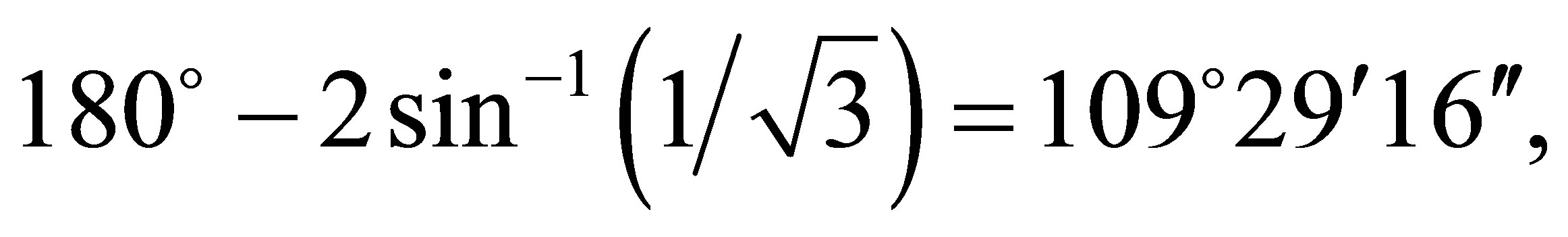
Two Lüders sheets, ABCD and EFGH, are shown in Figure 1. The line of intersection of these sheets meets the upper and lower plate surfaces at M and N at 135˚and 45˚ and the sheets intersect the upper plate surface forming traces AB and EH. Similar traces, or Lüders bands, can be seen on polished plates of mild-steel that have been deformed under plane stress in tension, where they are revealed by the Piobert effect, or they may also be revealed by etching [20]. The traces intersect on the plate surfaces at angles equaling  or
or
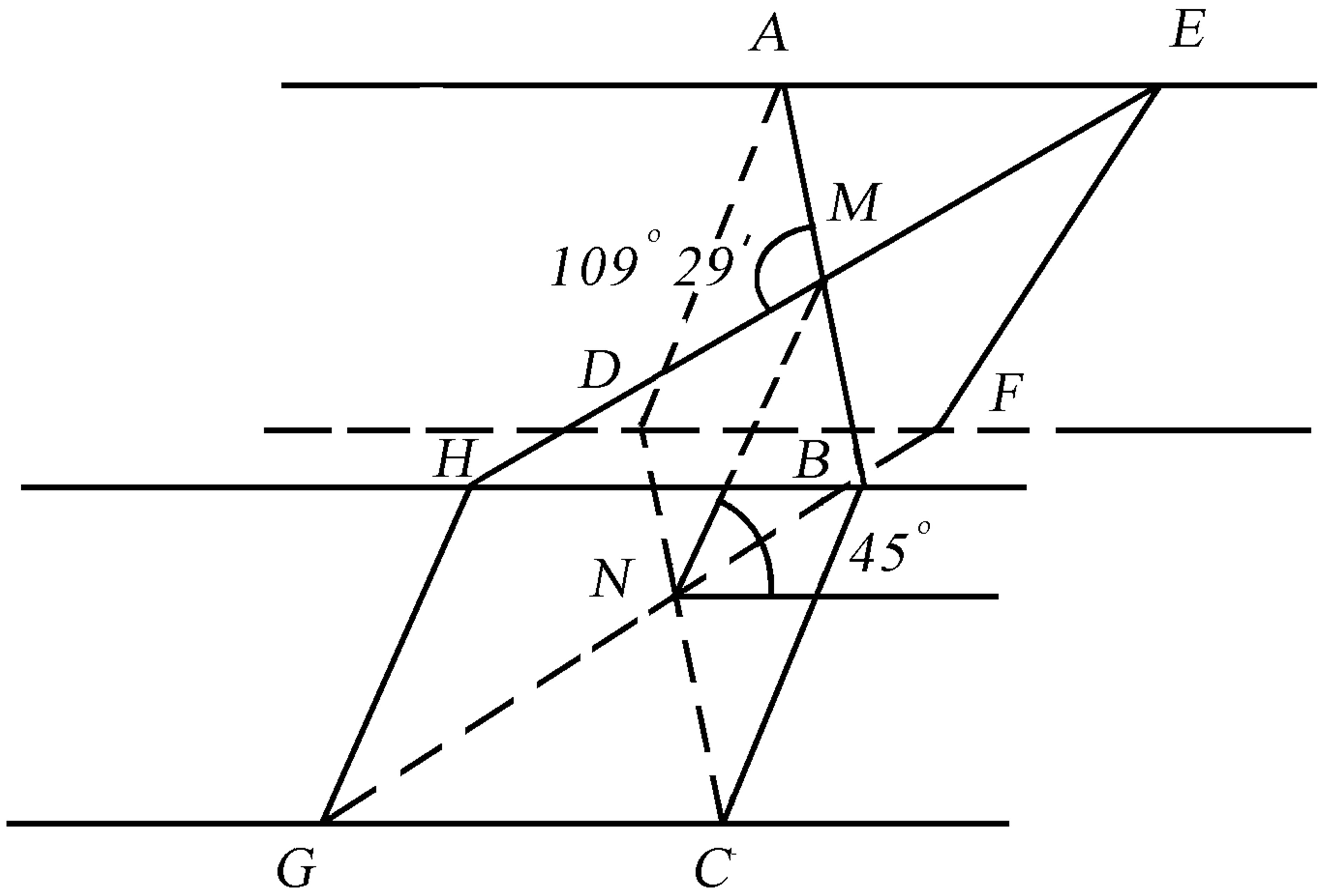
Figure 1. Travelling elastic/plastic boundary in a plate. The lines AE and HB lie on the upper plate surface.
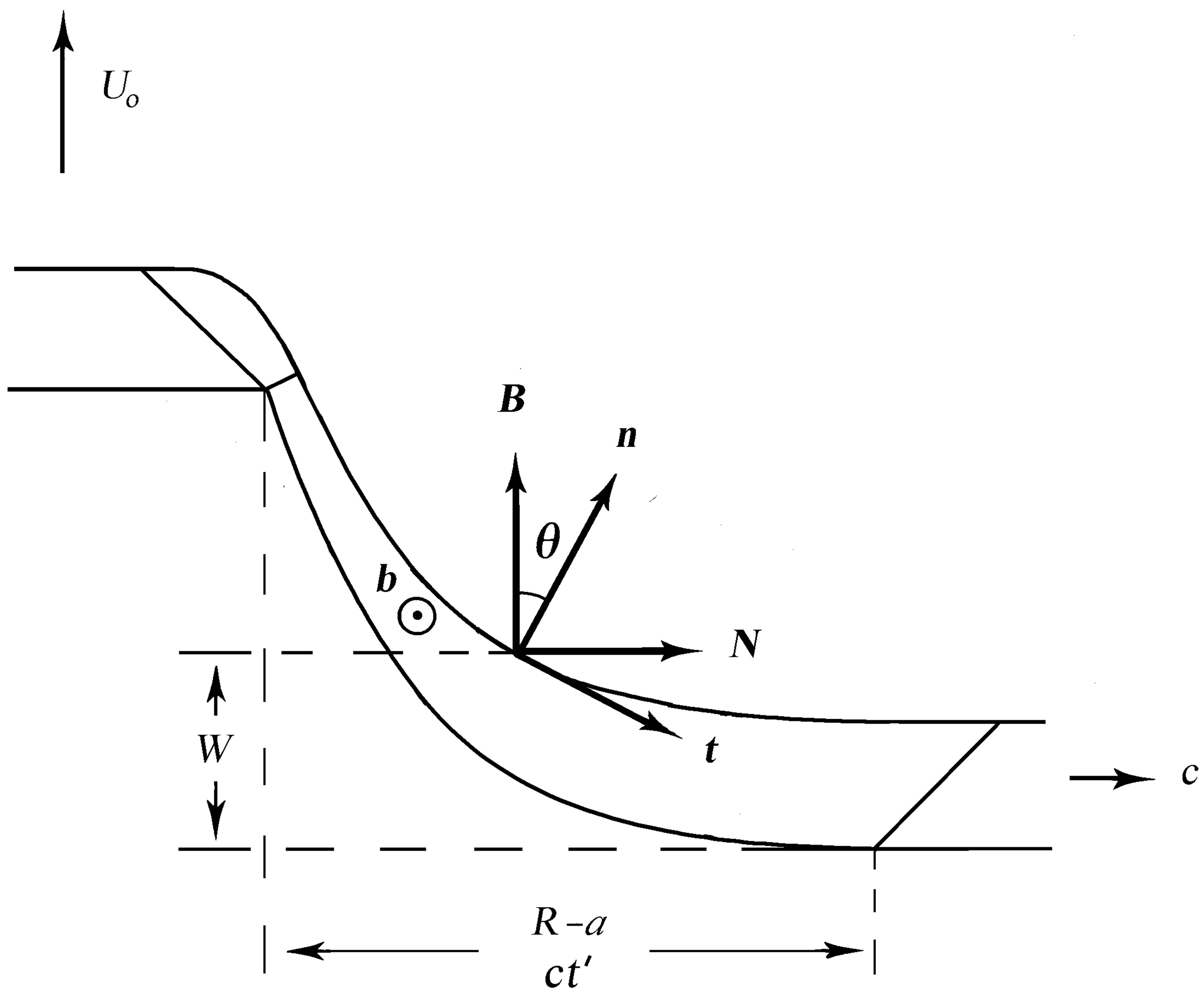
Figure 2. An axial plane through a transversely deflected free plate deflected by a rigid flat ended punch.
 while the Lüders sheets themselves intersect within the plate at right-angles. In Figure 1 classical Volterra dislocations travel in ABCD and EFGH, by extended slip, normal to the line MN at velocities limited by
  The aim here is to determine the speed with which MN advances along the bisector of
  in a direction parallel to the plate surface, i.e. along AE and HB. In the case of circular symmetry this velocity equals the rate of increase of the radial coordinate of N from the punch axis.
To obtain the limiting velocity of dislocations resolved normal to MN in the plane which is normal to the plate and which bisects , we must resolve the dislocation velocity,
  through 45˚. To find the velocity, in turn, of ABCDEFG along the plate we must, once again, resolve through 45˚. Therefore the velocity of the boundary to the plastic domain in the plate equals
 (2.1)
(2.1)
3. Principal Axes
Strains
Shown in Figure 2 is a section through a thin mild-steel plate struck at normal incidence by a rigid flat ended rod of arbitrary section. We define a unit vector; n normal to the distorted plate surface, a unit vector b along the closed contours of equal transverse deflection circulating about the punch and a unit vector t along the lines of steepest descent in the domain of plastic deformation. Letting  denote coordinates along the respective
  -lines, we can show that these are principal lines as follows.
Letting the stress deviator tensor have values  single subscripts signifying principal values, we propose that, in the case of dynamic deformation, the Tresca yield criterion must be modified to the dynamic biaxial strain form
 (3.1)
(3.1)
where k is the static shear yield stress of the plate material, which equals one-half of the lower tensile yield stress as measured, at very low loading rates, in an ordinary testing machine. We obtain from the second of these equations, by Equation (A.1), of appendix A, and incompressibility,
 (3.2)
(3.2)
where  denote the strain rate values, a single subscript again denoting a principal value. The state of strain to the left of the propagating front is bi-axial.
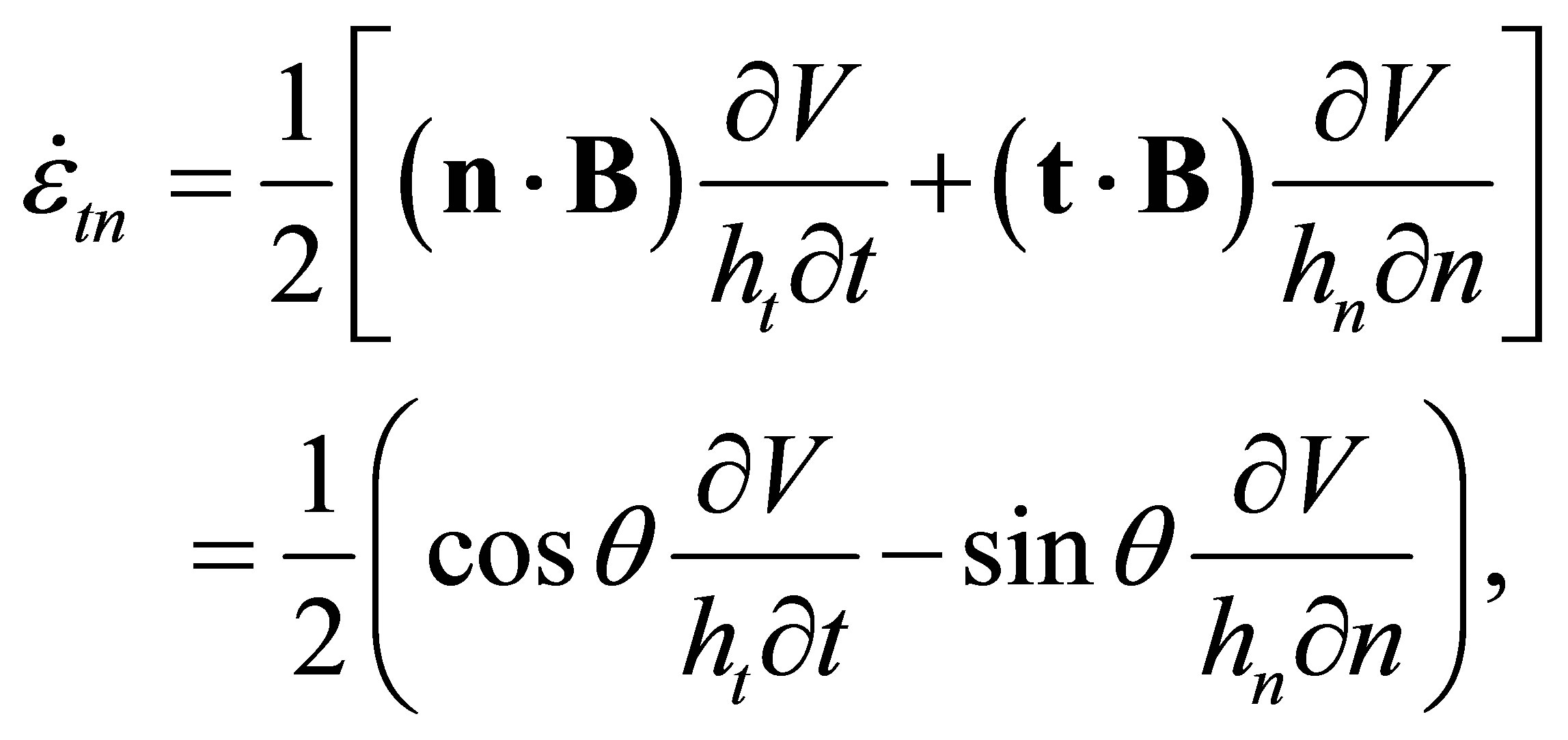
In general, letting V denote the velocity vector, the strain-rates are given by [8]
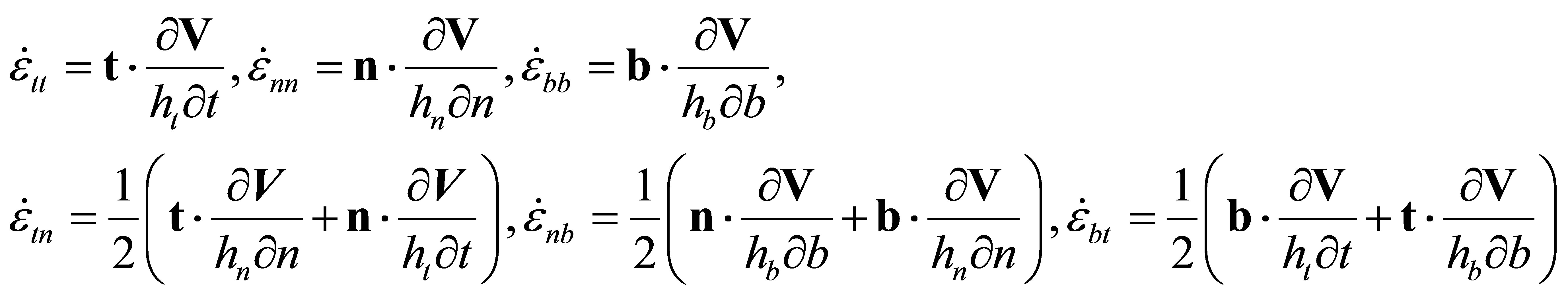 (3.3)
(3.3)
and from the second of Equations (3.2) and the third of Equations (3.3)
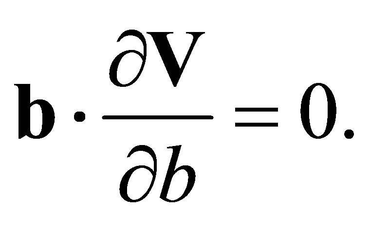 (3.4)
(3.4)
But, because  it follows that
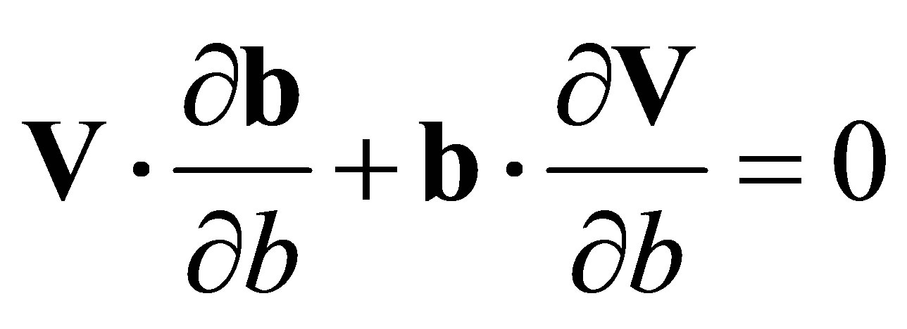 (3.5)
(3.5)
and from the two equations above we get
 (3.6)
(3.6)
The vector  is directed along the normal (in the sense of this term as it is used in Differential Geometry) direction to the b-lines, the N-direction. These lines are perpendicular to the punch axis. Thus the plate velocity at each point within the expanding plastic domain is directed precisely along the bi-normal direction to the b-lines, i.e. parallel to the unit vector B, which is parallel to the punch axis. This remains true no matter how large the plate deflections become and leads to the following theorem of plate plasticity;
Theorem 3.1 In the transverse deflection of a thin free plate deforming by extended slip, the velocity vector field within the plastic domain in the plate is directed along the bi-normals to the closed lines of equal transverse deflection, no matter how great the deflection.
We can now show that  as follows. Writing (Figure 2)
 (3.7)
(3.7)
since B is a constant unit vector, we have from the fourth of Equations (3.3)
 (3.8)
(3.8)
where θ is the angle of inclination of the plate normal to the punch axis. But V cannot vary in the B-direction, while the maximum rate of change of V is in the N-direction. From Figure 2 therefore, if  denotes an incremental distance in the N-direction with both t and n varying as N varies,
 (3.9)
(3.9)
and on substituting into Equation (3.8) we obtain
 (3.10)
This same result may also be obtained from the fact that, in the case of a thin plate, the stress value  must, by Newton’s third law, equal zero over the free region of the plate and therefore, by Equation (A.2), if the plate is thin,
 (3.11)
By the flow rule (Equation (A.1)) Equation (3.10) then follows.
Additionally, by Equations (3.3) and (3.7)
 (3.12)
and because  equals zero, by definition, and B is perpendicular to b it follows that
 (3.13)
Again, on the two plate surfaces over the free portion of the plate, the shear stresses vanish by Newton’s third law and therefore, by Equation (A.2),
 (3.14)
By Equation (A.1), again, we then obtain the first of equations (3.13). The second of Equations (3.13) with Equations (A.1) and (A.2) shows that the tand b-lines are lines of principal stress and strain-rate. We have therefore also proved a second theorem of plate plasticity;
Theorem 3.2 In the transverse deflection of a thin free metal plate obeying the Tresca yield criterion, the level lines of deflection and the lines of steepest descent in the plate are principal lines of stress and strain-rate.
This theorem follows immediately from Equations (3.10) and (3.13) because the Tresca yield criterion (Equation (3.1)) applies to a solid deforming by means of extended slip. Equations (3.11) and (3.14) show us that the plate must be thin, although how thick it may be before departures from the theory creep in is a matter that must be decided experimentally.
4. Deflected Configurations and Strains in Thin Free Plates
4.1. The Deflection of a Free Circular Plate
We consider a thin freely supported mild-steel plate struck by a flat ended rigid circular rod of radius a. The outer boundary (Figure 2) to the plastic domain propagates outward at speed c and if  denotes the time since impact
 (4.1)
(4.1)
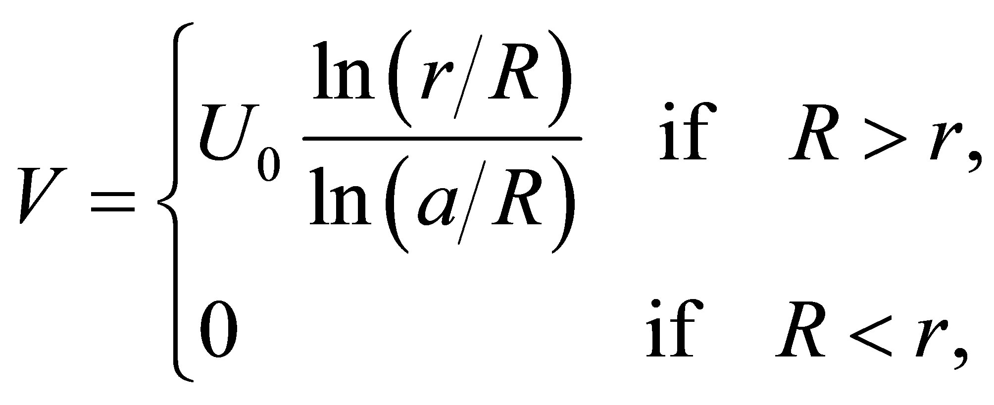
where R is the current radius of a cylinder, with its generators parallel to the punch axis, cutting the inner edge of the boundary It has been shown [8] that the velocity in the plate in the plastic domain may be obtained from Equation (A.10). By Equation (3.7), since B is a unit vector of constant direction, this equation, in the case of the circular plate and concentric circular punch of radius a, leads to the solution
 (4.2)
(4.2)
where V is now the (transverse) plate velocity in the plastic domain at radial distance r from the punch axis and  is the punch velocity, which is assumed, here, to remain constant.
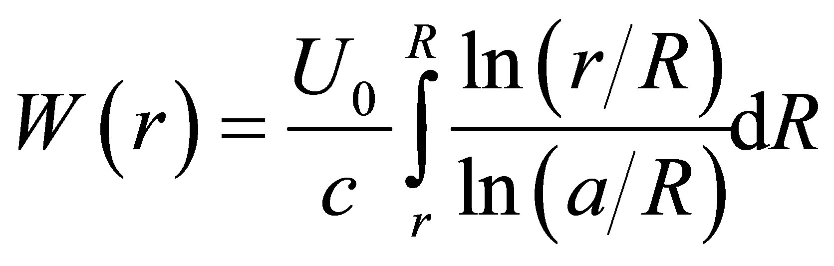
To obtain the plate profile at any time,  after impact we must integrate the right-hand members of Equation (4.2) over time, taking care to distinguish points within the plastic domain from those outside of it. Thus we get for the transverse deflection
  in the plate
 (4.3)
(4.3)
where the lower limit of integration is  because no deformation can occur at a point in the plate until the outer boundary passes that point. Writing
 (4.4)
(4.4)
we obtain
 (4.5)
(4.5)
and finally we make the substitution
 (4.6)
(4.6)
which leads to
 (4.7)
(4.7)
or
 (4.8)
(4.8)
Utilizing the Exponential Integral,
 (4.9)
(4.9)
we obtain
(4.10)
Differentiating this equation with respect to r leads to
 (4.11)
and therefore
 (4.12)
Differentiating once again we find that
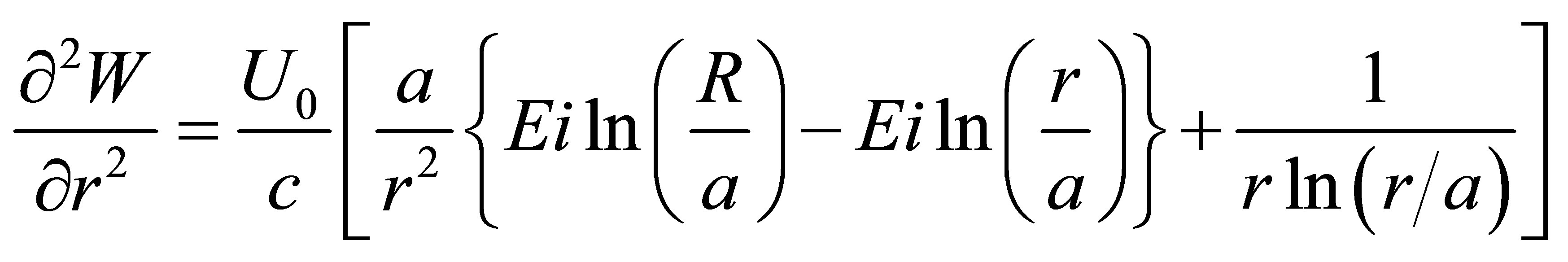
(4.13)
so that, at the travelling boundary,
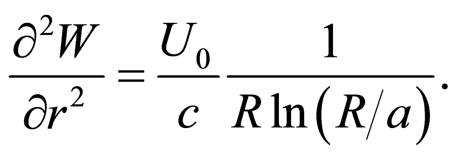 (4.14)
4.2. Principal Strains and Strain-Rates for the Free Circular Plate
A radial element of length,  in the circular flat plate, after deformation, assumes the new length
  as the plate deforms, becoming thinner and the principal strain along the t-lines therefore equals
 (4.15)
To obtain the principal strain-rates we differentiate this equation with respect to the time, using Equations (4.4) and (4.11). We then have
 (4.16)
 (4.17)
where, from Equation (4.11),
 (4.18)
From Figure 2
 (4.19)
leading to
 (4.20)
5. Inertial Forces and Principal Stresses
5.1. The Inertial Force
At contact an impulse  is delivered to the travelling punch by the static plate, where m is the mass of a disc in the plate equal in diameter to the punch. Subsequently the force acting on the punch may be found as follows.
From Equations (4.2) and (4.4)
 (5.1)
(5.1)
leading to
 (5.2)
(5.2)
Due to the total absence of radial deflections a ringshaped element of the plate of radii  has thickness parallel to the punch axis exactly equal to T, the initial plate thickness. The mass of this elementary ring is equal to
  where
where  is the mass density of the plate material and the inertial reaction force due to this elementary ring equals
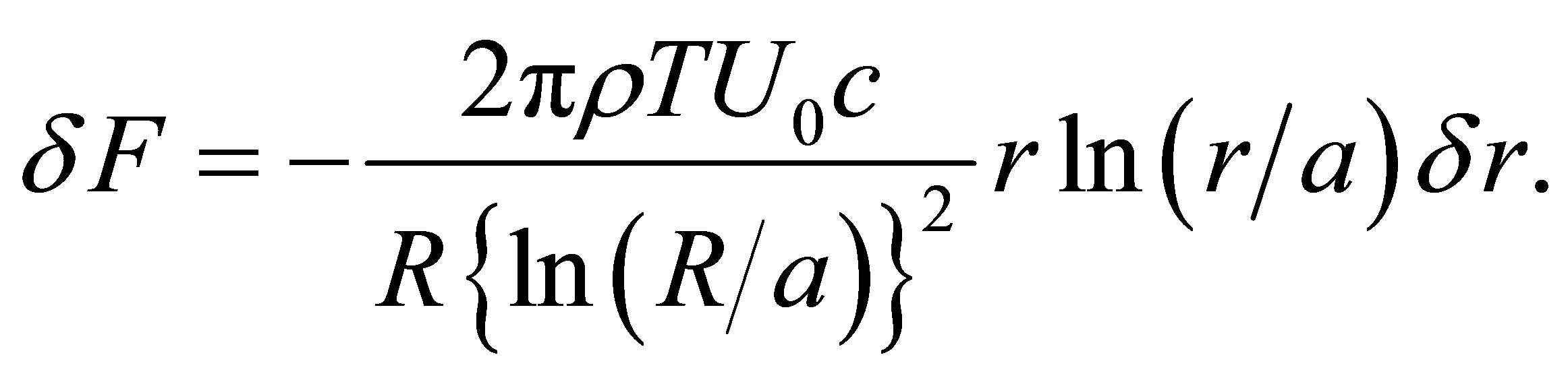 (5.3)
(5.3)
Writing  and integrating, we obtain for the total inertial force opposing the punch
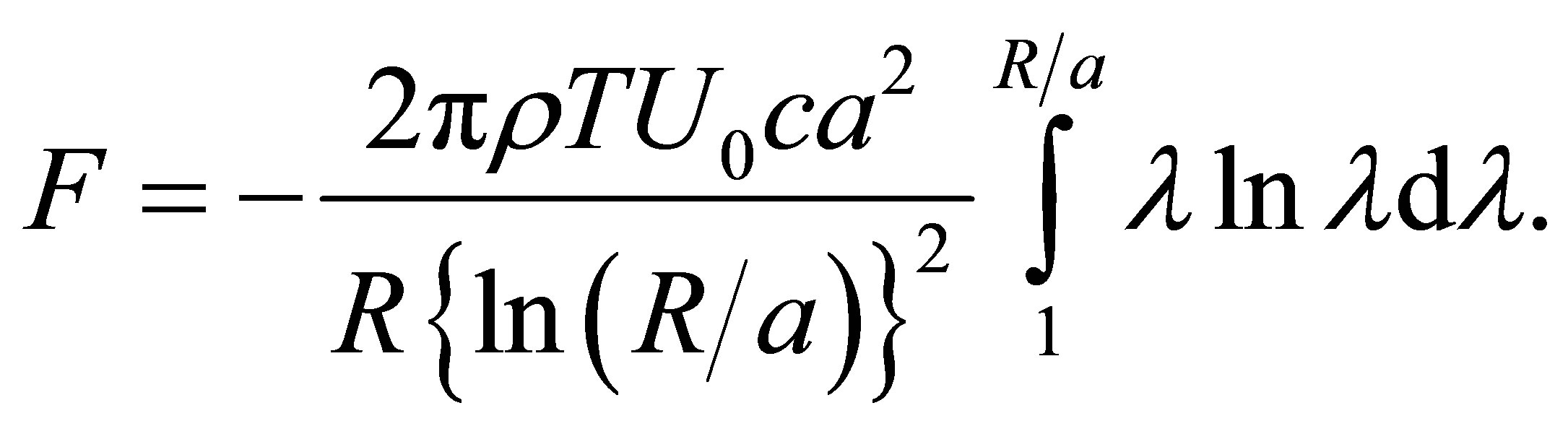 (5.4)
(5.4)
On carrying out the integration, the reaction force is found to equal
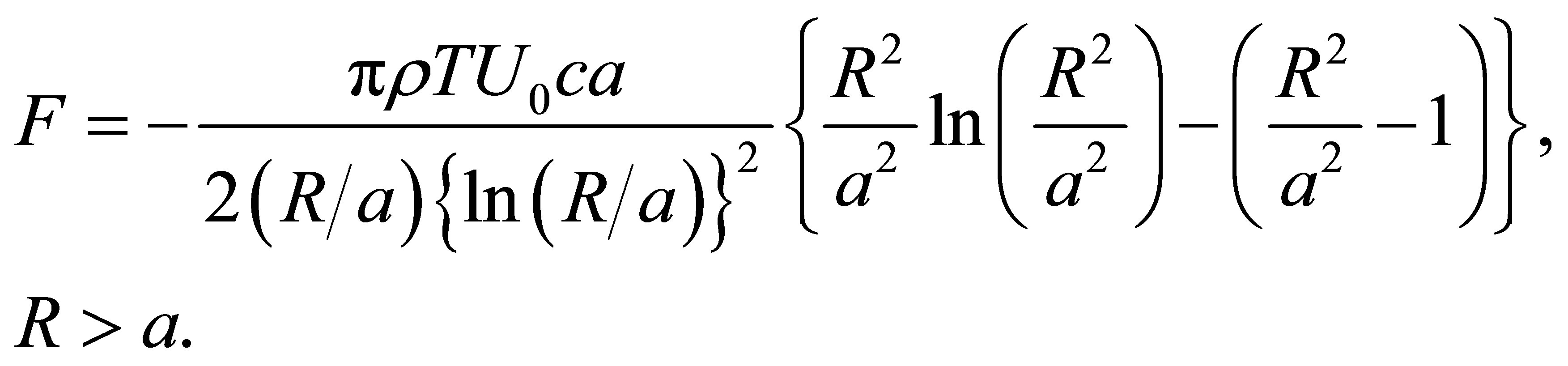 (5.5)
(5.5)
The value,  of this expression, subsequent to the initial impulse,
  can be obtained by means of L’Hopital’s rule for finding limits of expressions of the form 0/0. Thus we get
 (5.6)
(5.6)
leading to
 (5.7)
(5.7)
5.2. Stresses
The stresses in the plate at the propagating boundary are related to the first invariant of the stress tensor as follows.
(5.8)
 (5.9)
(5.9)
 (5.10)
Due to circular symmetry, Equation (B.6), of Appendix B, is automatically satisfied in the case of the thin circular plate. But from Equation (B.5), inserting the ncomponent of the inertial body force per unit volume obtainable from Equation (5.2), we get
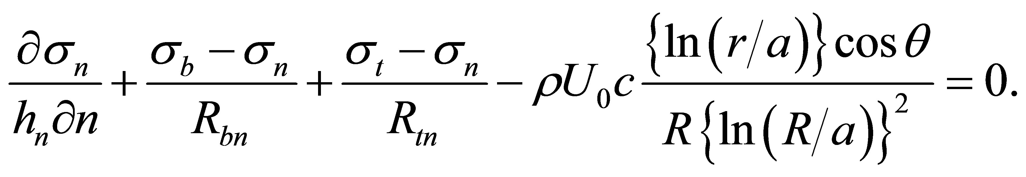
(5.11)
and for points at the propagating boundary, clearly,  so that, using Equations (4.12), (4.19) and (5.8) - (5.10) we get, from Equation (5.11),
 (5.12)
From Equation (B.8) we also have, writing r for 
 (5.13)
From Figure 2 we see that the increment in r corresponding to an increment in n with t fixed is given by
 (5.14)
and substituting into Equation (5.13) we then get
 (5.15)
For  we use the familiar formula found in works on the differential calculus,
 (5.16)
the sign being positive because the centre of curvature lies in the first quadrant of the  From Equations (4.11), (4.14), (4.19) and (5.16) we therefore finally obtain
 (5.17)
 (5.18)
The radii of curvature  have been calculated for
 , using Equations (5.15), (5.17) and (5.18), and are shown in Figure 3. Equations (5.12), (5.15) and (5.18) now lead to
 (5.19)
and substituting for  from Equation (5.17) we finally obtain
 (5.20)
From Equations (5.8) - (5.10) we then get for the principal stresses acting in the plate, at the boundary,
 (5.21)
6. Discussion and Conclusions
6.1. Discussion
In the above analysis, plasticity enters in the form of the solenoidal property of the strain-rate tensor [8-12], which is the mathematical expression of the new physical law regulating plastic deformation in solids that deform by means of the mechanism of extended slip. Combining this with the flow-rule associated with the Tresca yield criterion and introducing a hypothetical propagating boundary, an exact description, disregarding the very much smaller elastic deformation, can be made of the geometric form of the plate at any instant during its deformation. This analysis teaches us that, as with clamped and statically punched plates of mild-steel and ARMCO iron [9,12], as well as many cold-rolled sheet metals, the plate thickness measured parallel to the punch axis remains equal to the original thickness of the un-deformed plate.
From the analytic treatment an exact description can then be made of the transfer of momentum from the punch to the plate and it has been assumed that the plate is heavily over matched. Thus we obtain the force acting. Then the stress equilibrium equations, which contain the above inertial force, are introduced. These equations show us that at the propagating boundary, on its plastic side, the normal stress equals the product of the mass per unit volume of the plate and  where c is the boundary wave speed, which has been shown to equal one-half of the velocity of elastic waves of rotation in the solid.
The very high magnitudes of the stresses inside the propagating boundary are due to the fact that plastic flow remains impossible at any point of the plate until the boundary wave has passed that point. The dissipationrate in the plate is given by the first term in the righthand member of Equation (C.6), of Appendix C, and in the case of the circular plate this term is initially zero. A simple calculation reveals the overriding dominance
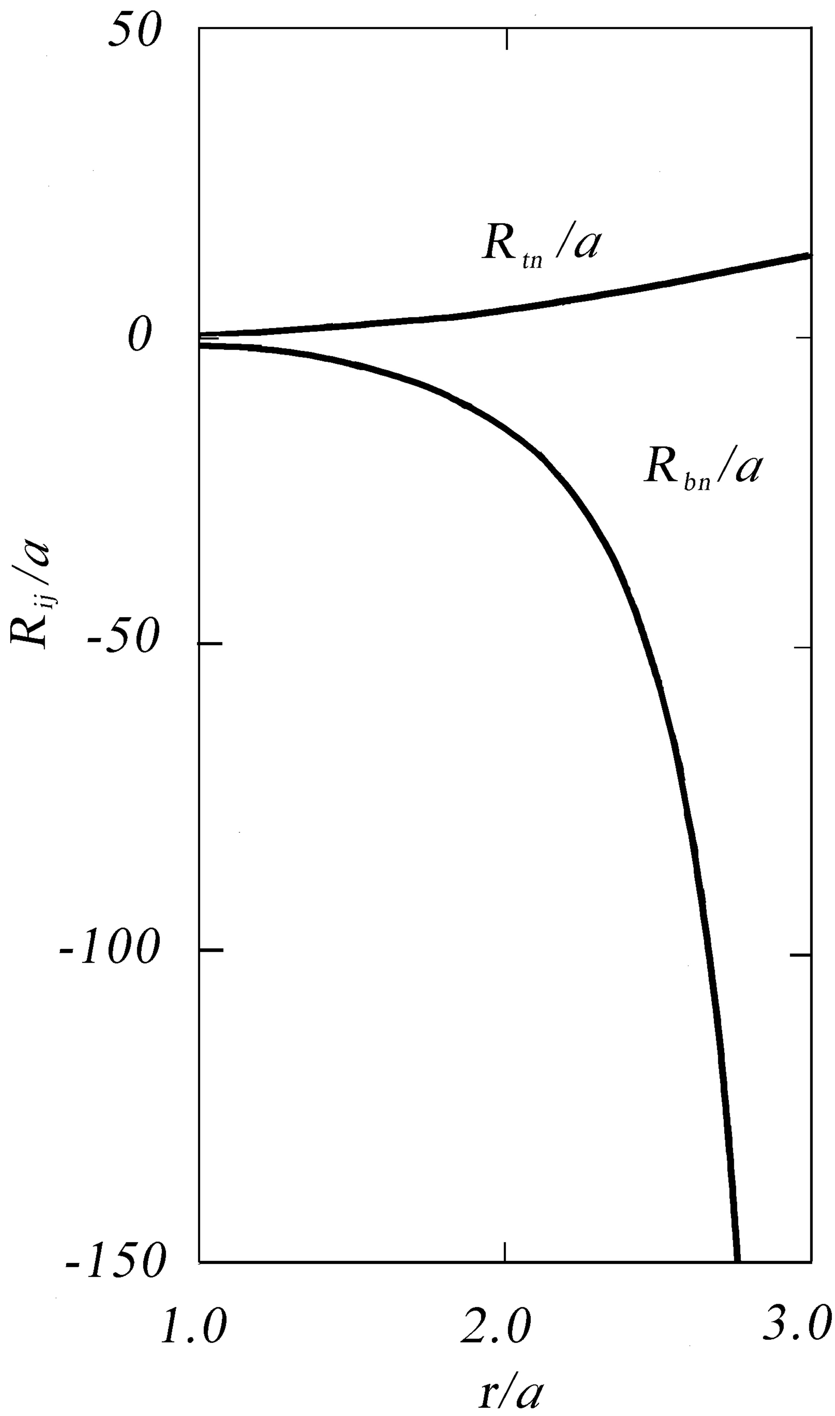
Figure 3. Radii of curvature in the two principal tangent planes that are normal to the plate surface. The calculated results are for 
of the Kinetic energy term when punch velocities are measured in hundreds of meters per second.
The theoretical deflection profile on a mild steel plate may be calculated using Equations (4.10)-(4.12). Figure 4 shows the profile produced in a free plate of mild steel by a rigid circular rod, 0.5 in (12.7 mm) in diameter, moving at  with
with  15 μs after contact (Young’s modulus equals
  the density of iron is 7.87
  and Poisson’s ratio for iron has the value 0.280) [21]. The calculations were performed using tables [22] of the exponential integral.
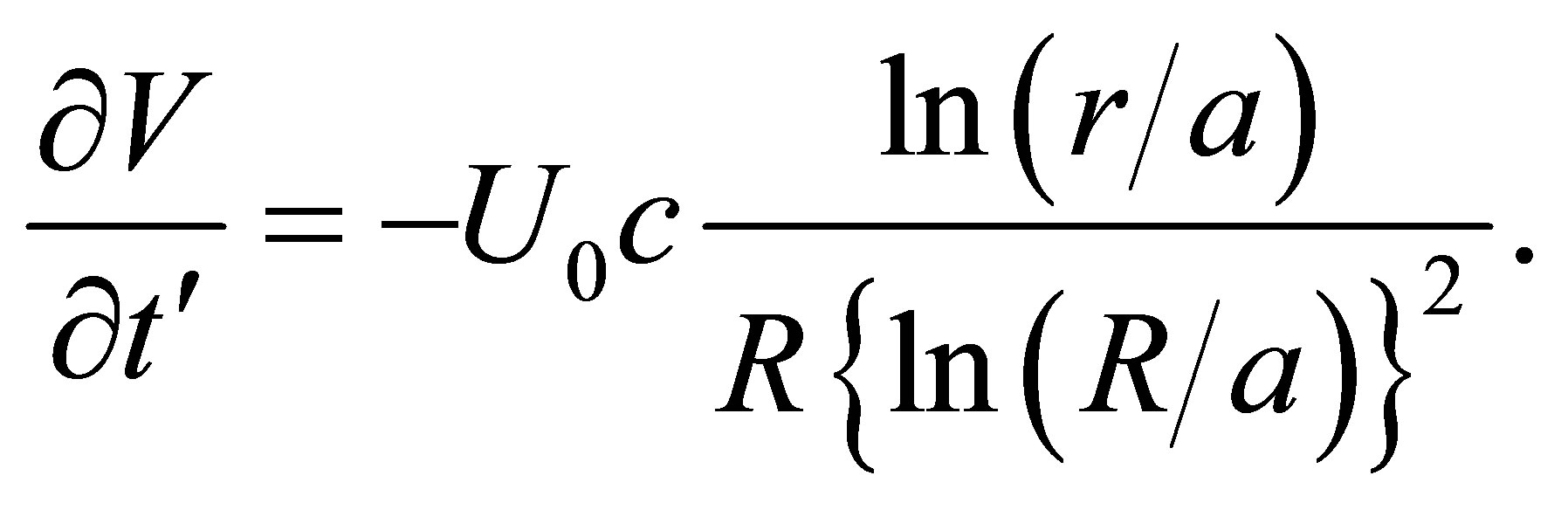
In connection with experimental testing it needs to be noted that the gradient in the plate deflection while vanishing at the propagating boundary remains small for some considerable distance inside this boundary. Moreover, the thickness, T, of the plate measured parallel to the punch axis equals the initial plate thickness and the true plate thickness, T', is given by  The testing of this formula constitutes a Metrological problem but provides a stringent test of the dynamic theory.
In the punching of clamped plates at low velocities, Wen and Jones [23] assume Equation (4.2) for clamped plates impacted at low velocities (R is in this case is the radius of the clamping circle) on an empirical basis. In the present analytical treatment, however, flow in the
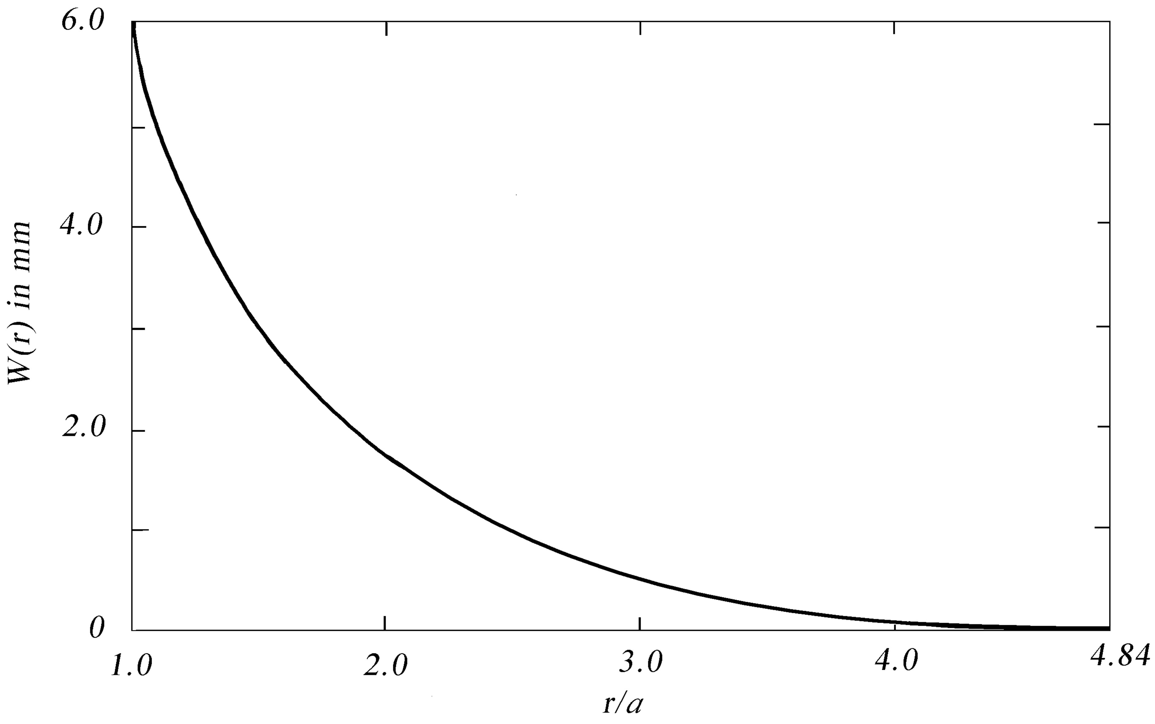
Figure 4. Calculated profile on a mild-steel plate struck at normal incidence by a rigid flat-ended circular rigid rod, of radius 12.7 mm, moving at 400  15 μs after initial contact.
plate occurs by extended slip so that Equations (A.7) and (A.10) and the physical law on which these equations depend are applicable; Equation (A.7) always holds for mild-steel. By Theorem 3.1 or, indeed, Equation (3.1) and the flow-rule expressed by Equations (A.1) and (A.2), it follows that the state of strain in the plate is completely bi-axial so that there are no radial deflections, even for indefinitely large punch deflections. This is also true for the quasi-static punching of clamped plates [9].
The results of experimental investigations [18] suggest that in metals the overstress is a function of strain-rate and many writers have assumed that the strain-rate causes the overstress. Yet the strain-rate is an effect, it is not a cause.
The physical law expressed by Equations (A.7) and Equations (A.10) and (4.2) derived from Equations (A.10) and (3.7), with the boundary wave hypothesis and the modified Tresca yield criterion (Equations (3.1)), lead directly and unequivocally to Equations (4.10) - (4.12), (5.5), (5.7), (5.15), (5.17), (5.18) and (5.21). It is proposed here therefore, on the basis of the analysis, that the factor that influences the overstress and associated strainrates can be no other than the limitation on dislocation velocity imposed by the finite speed of elastic rotational waves in the solid concerned. Furthermore the proposition is here set forth that it is this limit that gives rise to the propagating boundary, driven by the stress  which in turn confines plastically deforming material causing the high associated inertial stresses. In the case of any given material flowing plastically by means of the mechanism of extended slip, it is further postulated that it is this effect, not phonon drag, that causes the curve of stress versus strain-rate, to turn becoming parallel to the stress axis as the associated dislocation velocities approach the speed of elastic waves of rotation in the solid concerned.
Before we consider the conclusions that can be drawn from the analysis above, we should examine carefully the assumptions on which it rests. These are:
(1) Equation (A.7) continues to apply to a solid deforming by extended slip not only under static but also under dynamic loading conditions, i.e., the strain-rate tensor is always solenoidal if plastic flow occurs by means of extended slip.
(2) In the impact of a rod on a plate, an inertial body force, arising from the action of the propagating boundary, produces an overstress. The boundary propagates because dislocations are unable to move at velocities beyond the speed of elastic waves of rotation in the solid concerned.
(3) Under dynamic loading the Tresca yield criterion must be modified according to Equations (3.1). We note that at an edge on the static Tresca yield cylinder, the normal, which features in viscoplastic treatments, is not definable.
6.2. Conclusions
On the basis of the above assumptions it has been shown analytically that for a rigid flat ended rod impacting a thin free plate of mild-steel, at normal incidence and constant velocity:
(i) The boundary to the domain of extended slip in the plate propagates normal to itself, consistently with Huygens principle, at a velocity equal to one-half of that of elastic waves of rotation in mild-steel (Equation (2.1)). Lüders bands inside the plastic domain differ from those shown in Figure 1. The Lüders bands within the plastic domain are associated with biaxial strain. The strain along the b-lines circulates about the punch equaling zero.
(ii) No matter how great the transverse deflection in the plate is, the plate velocity vector field remains aligned precisely with the punch axis (Equation (3.7) and Theorem (3.1)). Consequently the plate thickness measured parallel to the punch axis remains precisely equal to the original true plate thickness and the velocities of points in the plate vary at their maximum rate along the N-direction (Figure 2).
(iii) The lines of equal deflection (level-lines) in the plate and those of steepest descent are principal lines, (Equations (3.10), (3.13) and (3.11) and (3.14), (A.1) and (A.2) and Theorem (3.2)).
(iv) The plate deflection within the domain of extended slip in a circular plate is given by Equation (4.10) (Figure 4).
(v) At the propagating boundary in the plate the gradient in deflection vanishes (Equation (4.12)) and the strain at the propagating boundary equals zero (Equation (4.15)).
(vi) The principal stresses acting along the lines of steepest descent in the plate (t-lines) and along the lines of equal deflection, circulating about the punch axis (b-lines), are essentially inertial for impact velocities measured in hundreds of meters per second.
(vii) The force opposing the punch following the contact impulse,  due to inertia of the plastic domain in the plate, is given by Equation (5.5).
(viii) The initial force on the punch, following the impulse  at contact, is given by Equation (5.7).
(ix) On the plastic side of the propagating boundary the principal stresses equal  (normal to the boundary) and
 (circumferential) (Equations (5.21).
The conclusions drawn above may be subjected to rigorous experimental tests in which freely supported plates are impacted by rods moving at velocities of several hundred meters per second. But in order to test the above equations and conclusions experimentally, it is necessary to note the fact that, by Equation (4.12), the gradient in plate deflection at the boundary to the plastic zone equals zero. The boundary is therefore not a travelling hinge as has been suggested by some writers, although it is predicted to travel at the speed of  in steel plates. Thus after a test, the boundary will not be detectable from measurements of deflection alone. To locate the boundary to the plastic domain after a test, differences in deflection after deformation but not the deflection itself need to be plotted against position in the plate. The position of the boundary then should be indicated by a cusp on the resulting curve of deflection differences versus radial distance from the punch axis. This suggested method for locating the boundary has been shown, in an earlier paper by the author [12], to serve in locating the junction between two adjacent plastic domains in a clamped plate of ARMCO iron deflected at its centre by a rigid sphere. Alternately a series of positions may be assumed for the boundary and the actual deflections on the plate compared with the predictions of Equation (4.10) until close agreement is obtained. The time of deformation is then the lip-height of the perforation rim on the plate divided by the punch velocity.
7. Acknowledgments
The author wishes to thank the reviewer(s) for their useful comments.
REFERENCES
- T. Karman and P. Duwez, “The Propagation of Plastic Deformation in Solids,” Journal of Applied Physics, Vol. 21, No. 10, 1950, pp. 987-994. http://dx.doi.org/10.1063/1.1699544
- K. A. Rakhmatulin, “Propagation of a Wave of Unloading,” Prikl. Mat. Melch., Vol. 9, 1945, pp. 449-462.
- L. Efron and L. E. Malvern, “Electromagnetic VelocityTransducer Studies of Plastic Waves in Aluminium Bars,” Experimental Mechanics, Vol. 9, No. 3, 1969, pp. 255- 262. http://dx.doi.org/10.1007/BF02325157
- G. I. Taylor, “The Plastic Wave in a Wire Extended by an Impact Load,” (The Scientific Papers of G. I. Taylor, Vol. I, Mechanics of Solids, Edited by G. K. Batchelor), Cambridge University Press, Cambridge, 1958.
- V. V. Sokolovsky, “Propagation of Elastic-Viscoplastic Waves in Bars,” Prikl. Mat. Mekh., Vol. 12, 1948, pp. 261-280.
- L. E. Malvern, “The Propagation of Longitudinal Waves of Plastic Deformation in a Bar of Material Exhibiting a Strain Rate Effect,” Journal of Applied Mechanics, Vol. 18, No. 2, 1951, pp. 203-208.
- P. Perzyna, “Fundamental Problems in Viscoplasticity,” Advances in Applied Mechanics, Vol. 9, Academic Press, New York, 1966.
- R. L. Bish, “Tri-Axial Deformation of a Plastic-Rigid Solid,” Acta Mechanica, Vol. 223, No. 3, 2012, pp. 655-668. http://dx.doi.org/10.1007/s00707-011-0580-1
- R. L. Bish, “Transverse Deflection of a Clamped MildSteel Plate,” Acta Mechanica, Vol. 223, No. 11, 2012, pp. 2411-2423. http://dx.doi.org/10.1007/s00707-012-0712-2
- R. L. Bish, “Plastic Shear Deformation of a Thin StrainHardening Disc: Variational Principles,” Philosophical Magazine, Vol. 91, No. 25-27, 2011, pp. 3343-3357. http://dx.doi.org/10.1080/14786435.2011.580285
- R. L. Bish, “Rotation-Rate Continuity in Bi-Axial Deformation,” Zeitschrift für Angewandte Mathematik und Mechanik, Vol. 84, No. 4, 2004, pp. 266-279. http://dx.doi.org/10.1002/zamm.200310098
- R. L. Bish, “Rotational Continuity in Thin Transversely Deflected Iron Plates,” International Journal of Mechanical Sciences, Vol. 43, No. 3, 2001, pp. 817-829. http://dx.doi.org/10.1016/S0020-7403(00)00028-X
- T. Børvik, O. S. Hopperstad, M. Langseth and K. A. Malo, “Effect of Target Thickness in Blunt Projectile Penetration of Weldox 460 E Plates,” International Journal of Impact Engineering, Vol. 28, No. 4, 2003, pp. 413-464. http://dx.doi.org/10.1016/S0734-743X(02)00072-6
- G. I. Taylor and H. Quinney, “The Plastic Distortion of Metals,” Proceedings of the Royal Society: London A, Vol. 230, 1931, pp. 323-362.
- A. H. Cottrell, “Theory of Dislocations,” Progress in Metal Physics, Vol. 4, Pergamon Press, London, 1953.
- J. J. Gilman, “The Plastic Resistance of Crystals,” Australian Journal of Physics, Vol. 13, No. 2, 1959, pp. 327-346. http://dx.doi.org/10.1071/PH600327a
- D. Hull, “Introduction to Dislocations,” 2nd Edition, Pergamon Press, Oxford, 1975.
- J. D. Campbell and W. G Ferguson, “The Temperature and Strain Rate Dependence of the Shear Strength of Mild-Steel,” Philosophical Magazine, Vol. 21, No. 169, 1970, pp. 63-82. http://dx.doi.org/10.1080/14786437008238397
- J. D. Campbell, “Dynamic Plasticity of Metals,” Springer Verlag, Wien, New York, 1972.
- R. L. Bish, “A Method of Revealing Deformation in Mild Steel,” Metallography, Vol. 11, No. 2, 1978, pp. 215-218. http://dx.doi.org/10.1016/0026-0800(78)90039-3
- G. W. C. Kaye and T. H. Laby, “Tables of Physical and Chemical Constants and Some Mathematical Functions,” 8th Edition, Longmans Green and Co., London, 1936.
- A. N. Lowan, “Tables of Sine, Cosine and Exponential Integrals,” Vol. 1, National Bureau of Standards (Edited by L. J. Briggs), 1940.
- H-M. Wen and N. Jones, “Low Velocity Perforation of Punch-Impact-Loaded Metal Plates,” Pressure Vessel Technology, Vol. 118, No. 2, 1996, pp. 181-187. http://dx.doi.org/10.1115/1.2842178
Appendix A
A.1. The Flow Rule
The flow rule for a solid deforming by extended slip may be expressed in the form,
 (A.1)
(A.1)
where E is the Cauchy strain-rate tensor, while the stress-deviator tensor, T, is defined in terms of the stress tensor, S, by
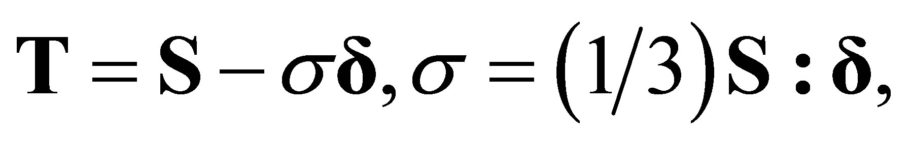 (A.2)
(A.2)
where
 (A.3)
(A.3)
and
 (A.4)
(A.4)
The vector notation is the same as in an earlier papers by the author [8,9].
From Equation (A.1) we have
 (A.5)
(A.5)
leading, by Equations (A.4), to
 (A.6)
(A.6)
A.2. Velocities
From the equation
 (A.7)
(A.7)
which characterizes flow by extended slip [8-12], and (see Equations (3.3))
 (A.8)
(A.8)
we obtain the differential equation regulating the transverse velocity in a plate. In fact, from the incompressibility condition
 (A.9)
(A.9)
and Equations (A.7) and (A.8), we get
 (A.10)
and by Theorem 3.1, because B is a constant vector, it follows that the scalar transverse velocity, V, is harmonic, i.e. It satisfies the Laplace equation. This means that if boundary values of V can be specified on the two boundaries in the plate then the velocity field within the plastic domain is uniquely determined.
Appendix B
If C is a closed surface surrounding a domain, D, of the plastic zone, we have by Newton’s second law
 (B.1)
(B.1)
where dv is an element of volume in D, n is the outward drawn unit vector normal to C and dA is an element of area on C, while  are, respectively, the mass density of the medium and the time, while S is the stress tensor and V denotes the velocity vector. Applying the Gauss divergence theorem, we obtain from Equation (B.1)
 (B.2)
(B.2)
and because D is arbitrary we therefore have
 (B.3)
(B.3)
Evaluating the divergence operator, as shown elsewhere [8], we obtain from Equation (B.3) the differential equations regulating the principal stresses,  These are
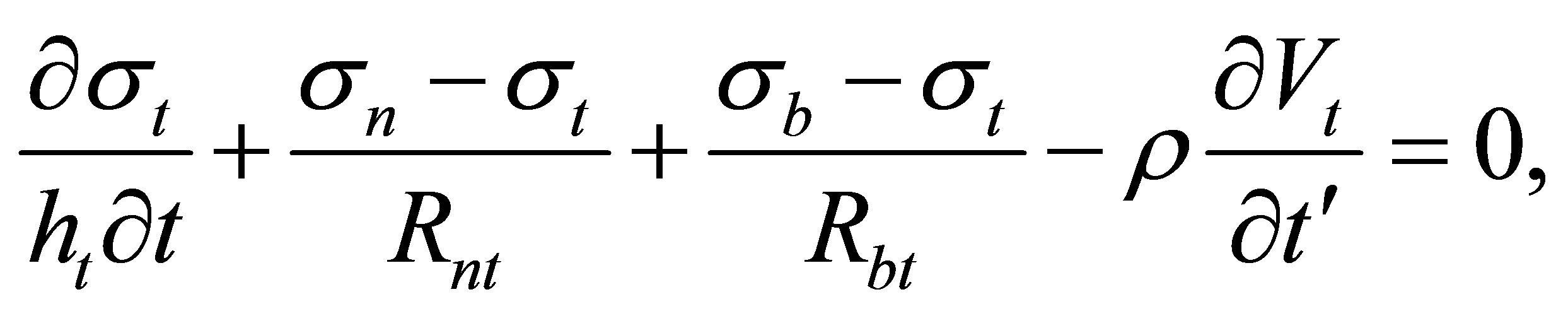 (B.4)
(B.4)
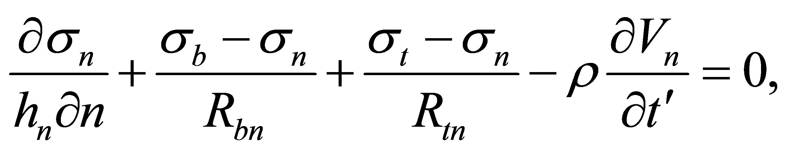 (B.5)
(B.5)
 (B.6)
(B.6)
where
(B.7)
(B.8)
(B.9)
are the curvatures of the principal lines in the local tangent planes to the  -curves. For instance
  is the radius of curvature of the n-line in the tangent plane formed by the local n and t vectors, while
  is the radius of curvature of the t-line in the same plane. A sign convention applies to Equations (B.7)-(B.9) stating that the curvature of a line in any given tangent plane is positive if its centre of curvature lies in the first quadrant and is negative if in the second quadrant.
Appendix C
Let a force, F, per unit area act over the surface C bounding a plastic domain D and let the element of area on C be dA and the element of volume in D be dv. Then
 (C.1)
(C.1)
where U is the velocity vector outside of C and V denotes the velocity vector field in D. This equation holds because the normal stresses and the normal velocities are continuous across C. Transforming the integral on the right by the Gauss divergence theorem we get
 (C.2)
(C.2)
But

(C.3))
by Equation (A.8) and the property  which follows from the equilibrium of moments of forces and Equations (A.1) and (A.2). From dynamic equilibrium Equation (B.3) with Equation (C.3) leads to
 (C.4)
(C.4)
and we therefore finally obtain, from Equation (C.2),
 (C.5)
(C.5)
It has therefore been shown that
 (C.6)
(C.6)
The first term in the right-hand member of this equation is the energy dissipation-rate within the plastic domain, while the second term represents the rate of increase of the kinetic energy delivered to the plastic domain. Calculation shows that the plastic dissipation-rate is negligible compared to the kinetic energy term in the case of a plate struck by a rod moving at velocities of several hundred meters per second.