World Journal of Mechanics
Vol.2 No.4(2012), Article ID:21538,6 pages DOI:10.4236/wjm.2012.24024
Oil Streak Visualization of Fluid Flow over Single D-Type Cylinder
Department of Mechanical Engineering, Faculty of Industrial Technology, Sepuluh Nopember Institute of Technology, Kampus Keputih, Surabaya, Indonesia
Email: astu@me.its.ac.id
Received May 29, 2012; revised June 26, 2012; accepted July 2, 2012
Keywords: Cut Angle; Drag Force; Visualization; Streamline
ABSTRACT
An experimental study on the effect of cut angle to the drag force on circular cylinders was performed. Six cylinders were cut at different angles of 0˚, 30˚, 45˚, 53˚, 55˚, and 75˚. The air flow impinges perpendicular to the cut surfaces of the cylinders. The shear layer visualization on the surface of the cylinders was conducted as well. The drag force was measured using a wind tunnel force balance and the wind speed was set in such a way that the corresponding Reynolds number of 5.3 × 10⁴ has been achieved. Visualization was carried out by covering the cylinder with paper wetted by mixture of oil and titanium dioxide powder.The experimental results show that the drag force has similar trend to that of previous experiment results. The minimum drag coefficient minimum is attained at the cut angle of 53˚. The streamline patterns of the flow past the cylinder could be reconstructed by judging the oil streak visualization.
1. Introduction
All objects submerged in a fluid flow experience aerodynamics forces due to the interaction between the objects and the flow. The forces can be generally categorized as drag and lift forces. Designing of airplane, car and ship bodies, building and industrial constructions, and rotor of turbomachineries require knowledge of these forces. Therefore, knowledge of the forces acting on the objects submerged in the fluid flow is a paramount importance [1,2].
Reduction of the existing forces act on an object can be done by controlling the boundary layer development on the object surface. There are many ways in controlling the boundary layer developed on the object surface. Object shape modification is one method that can be applied to handle it. Placing an object at upstream side of the mean object can also be used to modify the boundary layer development at the main object. These boundary layer controls can reduce the forces acting on the object.
There are many sphere shape objects that can be subjected to fluid stream, such as industrial gas tanks and sonar transducers to detect ocean depth. The reduction in drag by cutting the surface perpendicular to the incoming flow also works for a sphere placed in the fluid flow [3-5]. If the flow is not perpendicular to the cutting surface of the sphere, the flow will generate lift and change drag forces on the object [5].
Besides sphere shape, there are many other objects having circular cylinder shape submerged in fluid flow. These include electricity poles, bridge piles, industrial chimneys, tubes in heat exchangers, and supporting column for offshore constructions. If the circular cylinder shape object is cut on the portion up to a particular cut angle value, the drag on the object can be reduced [6-8] as shown by the result of Aiba and Watanabe [6] in Figure 1 (see graph for D type cylinder).
This paper is organized in four sections. The section of introduction is followed by the experimental apparatus and procedures section which explain the method of experimental i.e. the drag measurement and the oil streak visualization. The results of the drag measurement and oil flow visualization are discussed in Section 3 and then the whole work is concluded in Section 4.
2. Experimental Apparatus and Procedures
2.1. Drag Measurement
The experiment was performed in a subsonic wind tunnel with a test section of 30 cm × 30 cm. The free stream turbulence intensity, defined as ratio of root mean square (rms) of velocity fluctuation to the mean velocity at the centre of the test section, is about 0.8% at the all experiments. Six cylinders with diameter of 60 mm were used in the study and made of PVC. All cylinders have 100 mm length. One of these cylinders is a circular (without cut),
Figure 1. Plot of Cd as function of cut angle (q) for cylinder [6].
while the rests are cut at different angles on the front surface: 30˚, 45˚, 53˚, 55˚, and 75˚ (Figure 2). Surfaces of the cylinder were carefully smoothed to guarantee that the surfaces are aerodynamically smooth, and hence, the surface roughness effect can be neglected in this study. The upper view of the model test in the wind tunnel test section can be seen in Figure 3.
The drag force acting on the cylinder was measured using a force balance with uncertainty of 0.77% at measured drag force of 0.65 N and 2.47% at measured lift force of 0.202 N. The experiment was carried out at a wind tunnel Reynolds number of 5.3 × 10⁴ (based on fluid velocity V¥ and cylinder diameter D). This Reynolds number is chosen because at the range of Reynolds number 104 to 2 × 10⁵ for smooth cylinder the Cd is relatively constant [2]. Therefore if there is any velocity fluctuation of the freestream in that range of Reynolds number, there is no change in Cd. The change of Cd is only because of changing in body shape of the object. Interaction between tunnel wall boundary layer and the cylinder boundary layer is assumed to be negligibly small. Fluid velocity at the center part of the test section was measured using a Pitot static tube connected to an inclined manometer containing kerosene. Room temperature was measured using thermometer, and this temperature was used to calculate the fluid density.
2.2. Oil Streak Visualization
Shear layer over surface of the cylinder could be obtained by oil streak visualization method. The cylinders
Figure 2. Upper view of model test.
Figure 3. Model test in the wind tunnel test section.
were covered by paper wetted by mixture of oil and titanium dioxide powder (Figure 4) and attached in the test section of the wind tunnel. This model test is then exposed to the fluid stream with similar Reynolds number of drag force measurement. The fluid flow will form the streaks on the paper.
3. Result and Discussion
From the data of experiments at the q = 45˚ the error band of the drag force is ±0.0329 N. The value of drag coefficient (Cd) as a function of cut angle for Reynolds number of 5.3 × 10⁴ is depicted in Figure 5. From this picture, it can be seen that the value of Cd as a function of cut angle is similar to the one investigated by Aiba and Watanabe (Figure 1). The shear layer visualizations are shown in Figures 6 through 11. It could be investigated that the shear layer formed is symmetric between upper and lower sides of the cylinder.
If fluid stream impinges the cylinder without a cut (Figure 5), the Cd is still high because the separation occurs at an angular distance less than 90˚. This result is in accordance with visualization result of [9]. Such
Figure 4. Three dimensional view of a model test covered by paper wetted by mixture of oil and titanium dioxide powder.
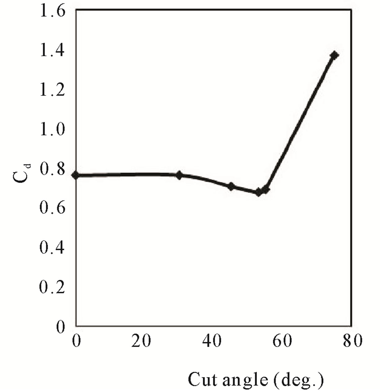
Figure 5. Variation of Cd with θ at Reynolds number of 5.3 × 10⁴.
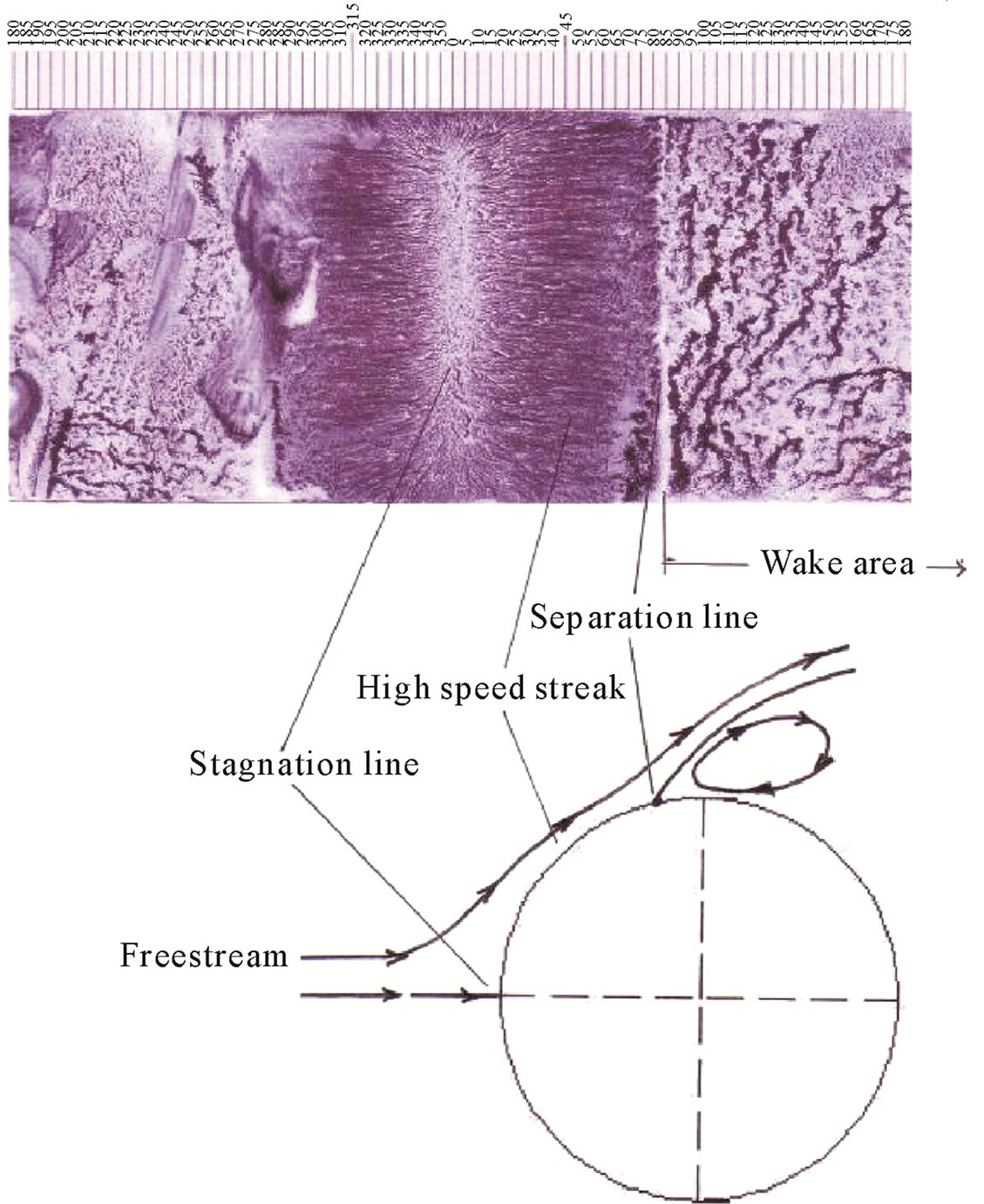
Figure 6. Shear layer visualization and reconstruction of streamlines pattern of the flow over cylinder without cutting.
separation is often referred to a laminar separation. Behind this separation line is wake area. From the streamlines pattern it can be seen that the wake area is very wide (Figure 6) and cause high drag.
If the flow impinges the cylinder with 30˚ cut angle, the value of Cd will decrease (Figure 5). It can be explained that the flow forms multi stagnation points on cut surface (Figure 7). The area of stagnation is slightly smaller than the area of cut surface. The flow at the upper side of this area will strongly be deflected more than that at the cylinder without cut. The fluid flows through converging stream tube. Hence the fluid moves with higher acceleration. This phenomenon is shown by the smoother high speed streak at oil flow picture. In this stream tube the flow is still laminar. The flow regime at the corner of cut surface will change from laminar to transition. After that it becomes turbulent, and the separation will be retarded due to turbulent flow is more capable to resist the adverse pressure gradient. The wake area and the drag is smaller than those of the cylinder without cutting.
The value of Cd for cylinder with 45˚ cut angle is smaller than that of 30˚ cut angle because the massive separation occurred at the surface of the cylinder is retarded due to formation of bubble separation at the corner of cut surface (Figure 8). So the wake area behind the
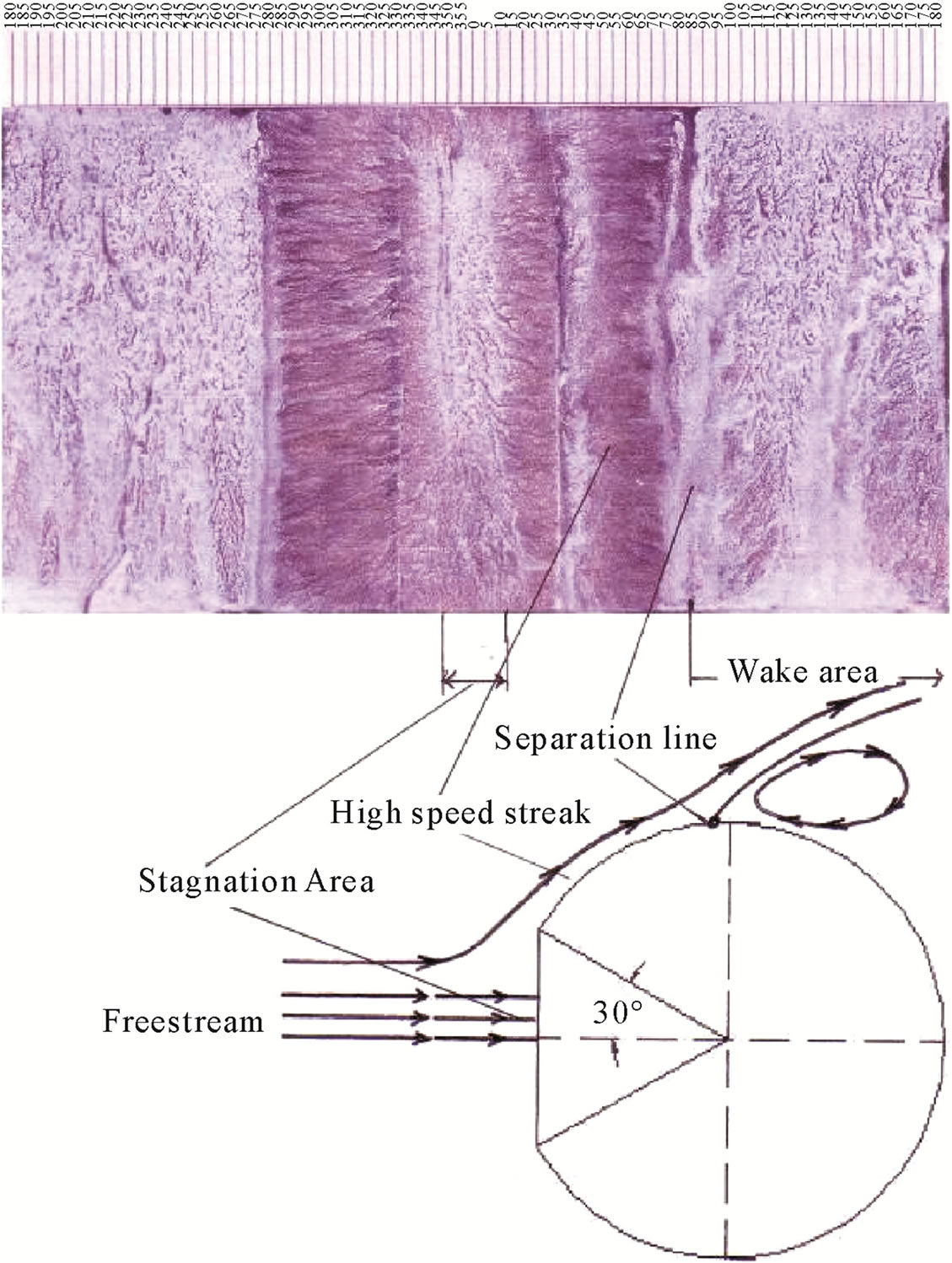
Figure 7. Shear layer visualization and reconstruction of streamlines pattern of the flow over 30˚ cut cylinder.
separation line becomes smaller.
Figure 5 shows that the minimum Cd is about 18.26% higher than result of Aiba and Watanabe [6], nevertheless these experiments conducted at higher Reynolds number. The phenomenon of the flow over 53˚ cut angle cylinder (Figure 9) is similar to the phenomenon of the flow over 45˚ cut angle (Figure 8). The distinction is that the surface behind the corner of cut surface is flatter than that of 45˚ cut angle. Hence the formed bubble is shorter, the reattachment area is longer, and the separation occurred is retarded.
At the cut angle more than 53˚, the flowing fluid impinges a wider plane surface causing the higher drag force contributed by the pressure drag (Figures 10 and 11). These phenomena are similar to those occurred in flowing fluid over cut spheres [3-5].
4. Conclusions
Generally, there is no lift force generated from the existence of fluid stream perpendicular to the cutting surface of cut cylinders. The drag force however, decreases gradually if the cutting angle is increased until some certain value (i.e. 53˚). Beyond this certain cutting angle, the drag force is increased again. The conclusions of the research are explained bellow:
1) If fluid impinges cut cylinder without turning angle (perpendicular to the cut surface) there is no lift force
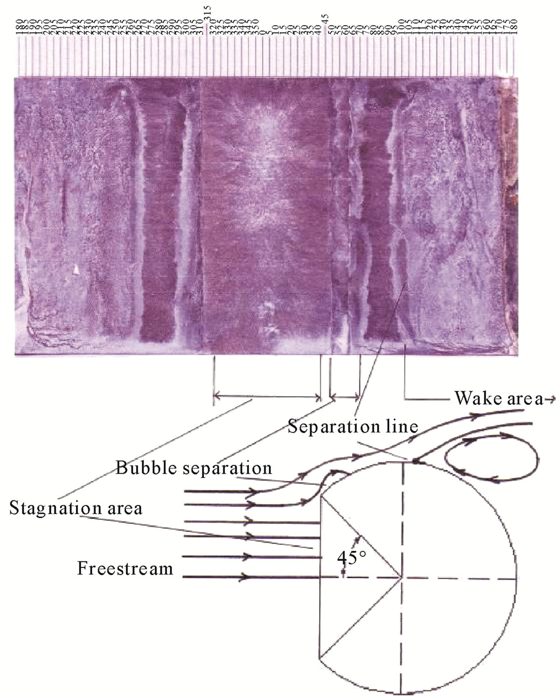
Figure 8. Shear layer visualization and reconstruction of streamlines pattern of the flow over 45˚ cut cylinder.
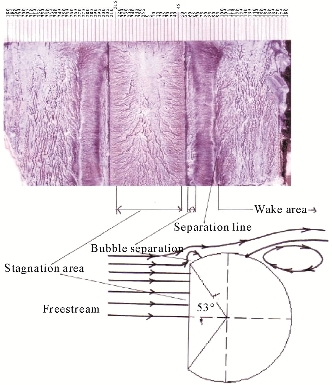
Figure 9. Shear layer visualization and reconstruction of streamlines pattern of the flow over 53˚ cut cylinder.
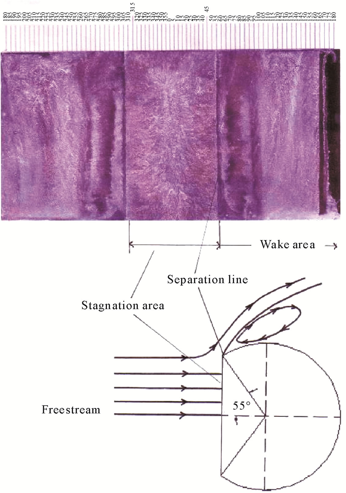
Figure 10. Shear layer visualization and reconstruction of streamlines pattern of the flow over 55˚ cut cylinder.
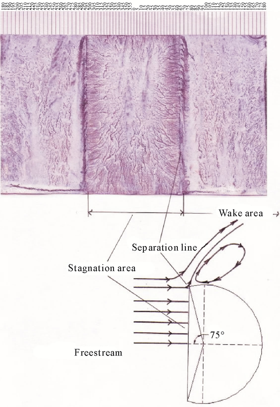
Figure 11. Shear layer visualization and reconstruction of streamlines pattern of the flow over 75˚ cut cylinder.
acting on the cylinder. The streamline pattern is symmetric between upper and lower sides.
2) The reduction of wake area at the downstream will reduce the drag force acting on the cylinder.
3) Present result shows that the Cd minimum is attained at cut angle of 53˚. This result is in accordance with the previous results [6,8]. The minimum Cd is about 18.26% higher than result of Aiba and Watanabe [6]. Nevertheless the present experiment was conducted at higher Reynolds number. So the drag forces generated are different, i.e. the higher Reynolds number generates higher drag force.
4) If the cut angle is more than 53˚ the drag force acting on cylinder becomes higher. This is caused by flow separation which suddenly occurs at the corner of cut surface.
5) Oil streak visualization could be used in reconstructtion of the streamlines pattern of flow over a body.
5. Acknowledgements
The author would like to thank his student, Burhan Adiguna for his assistance in this experiment. The support of the Fluid Mechanics Laboratory staff, Department of Mechanical Engineering, Sepuluh Nopember Institute of Technology (ITS) Indonesia is greatly acknowledged.
REFERENCES
- A. Roshko, “On the Drag and the Wake of Bluff Bodies,” Journal of Aeronautical Science, Vol. 22, 1955, pp. 124- 132.
- R. W. Fox, A. T. McDonald and P. J. Pritchard, “Introduction to Fluid Mechanics,” 6th Edition, Chapter 9, John Wiley and Sons, Inc., New York, 2004, pp. 409-466.
- S. Aiba, “Fluid Dynamic Drag of an Axially Symmetrical Bluff Body Consisting of a Plane Surface and Spherical Surface,” Journal of Fluids Engineering, Vol. 120, No. 4, 1998, pp. 851-853. doi:10.1115/1.2820750
- N. Adityawarman, “Experimental Study on the Effect of Variation Cutting Angles on Spheres to the Drag,” Bachelor Final Project, Department of Mechanical Engineering, Sepuluh Nopember Institute of Technology, Surabaya, 2000.
- A. Pudjanarsa, “Experimental Study on the Effect of Turning Angle on Drag and Lift Forces for Various Cut Angles on Spheres,” Journal of Mechanical Engineering Science, Vol. 221, No. 3, 2007, pp. 303-306. doi:10.1243/0954406JMES412
- S. Aiba and H. Watanabe, “Flow Characteristics of a Bluff Body Cut from a Circular Cylinder,” Journal of Fluids Engineering, Vol. 119, No. 2, 1997, pp. 453-454. doi:10.1115/1.2819155
- I. Andriyono, “Experimental Study on the Effect of Cut Angle on Cylinder to the Drag Force,” Bachelor Final Project, Department of Mechanical Engineering, Sepuluh Nopember Institute of Technology, Surabaya, 1999.
- R. Efendi, “Experimental Study on the Characteristic of Fluid Flow over D Type Single Cylinder,” Bachelor Final Project, Department of Mechanical Engineering, Sepuluh Nopember Institute of Technology, Surabaya, 2007.
- Y. Triyogi, D. Suprayogi and E. Spirda, “Reducing the Drag on Circular Cylinder by Upstream Installation of an I-Type Bluff Body as Passive Control,” Journal of Mechanical Engineering Science, Vol. 223, No. 10, 2009, pp. 2291-2295. doi:10.1243/09544062JMES1543
Appendix
Notation
Alphabet:
Cd: drag coefficient =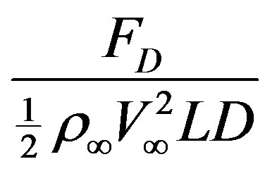 ;
;
Re: reynolds number = ;
;
L: cylinder length, m;
D: cylinder diameter, m;
FD: drag force, N;
 : freestream velocity, m/s.
Greek:
q:  = cutting angle;
 : dynamic viscosity of freestream, kg/m·s;
 : freestream density, kg/m3.