World Journal of Mechanics
Vol.2 No.3(2012), Article ID:19990,9 pages DOI:10.4236/wjm.2012.23017
Vibration Control of a Plate Subjected to Impulsive Force by Plate-Type Dynamic Vibration Absorbers
Laboratory of Modelling and Simulation in Engineering, Biomimetics and Prototype, Faculty of Sciences, University of Yaounde I, Yaounde, Cameroon
Email: *nananbendjo@yahoo.com
Received April 29, 2012; revised May 20, 2012; accepted May 28, 2012
Keywords: Plate; Impulsive Force; Vibration Control
ABSTRACT
This paper examines modelling of the dynamics of a plate by plate type dynamics vibration absorber subjected to a localized periodic impulsive excitation. An analytical solution of the modal equation is proposed and validated using direct numerical simulation of the basic equations. The basics equations are solve numerically using fourth order Runge Kutta algorithm. Various types of dynamic absorbing plate are tested to optimize the control efficiency. Particular attentions have been paid on the effects of localization of external forces on the dynamics response of the system under control. Ours findings demonstrate that a good achievement of control strategy should follow the above mentioned analysis.
1. Introduction
The problems of reduction of structural vibration induced by external force have constituted a great source of interest in recent years [1-4]. These excitations can be natural such as earthquakes, wind etc. or due to mechanical action. In both cases, this can lead to premature destruction of the system. One of the most famous examples illustrating these remarks is found in the Tacoma Narrows Bridge (USA, 1940) which was destroyed following an excitation by the wind. Several solutions have then been considered for this purpose. They range from simple archaic solutions such as destruction of these structures, to more modern solutions using techniques of vibration control which offer the advantage of being both less costly and more effective. Therefore, investigating vibration control of a plates become important in structures and mechanical systems design. To cope with these disturbances, many vibration control techniques have been developed such as sandwich control [5-8], electro-mechanical control [9-11], piezoelectric control [12,13], magneto rheological control [14], opto-electromechanical control [15,16].
In this paper, we are interested in the enhancement of viscoelastic control for a rectangular plate subjected to periodic impulsive excitation. The device is a three layers viscoelastic core subjected to localized periodic impulsive excitation. It is almost two rectangular plates of the same surfaces, hinged at both ends and possibly be made of different materials. The system is composed of two plates: One so-called main plate is subjected to impulsive external excitations located at point of contact, is coupled to another said dynamic absorbing plate by a viscoelastic coupling system consisting of identical springs and dampers with spring constant k and damping coefficient c respectively as shown in Figure 1. Therefore, several configurations of the coupling system can be used. We consider here the case of uniform distribution viscoelastic coupling.
In Ref. [17], Zhang et al. proposed to stabilize an elastic plate using viscoelastic boundary condition as feedback control. Hongpan et al. [18] investigated vibrations control of plate through electro-magnetic constrained layer damping which consists of, electromagnet layer, permanent layer and viscoelastic damping layer. Moreover, Aida et al. [6,7] have modelled the dynamic and optimized control by sandwich of a plate (and beam) under sinusoidal periodic excitation. They have shown

Figure 1. Main plate and dynamic absorbing plate with uniformly distributed connecting spring and dampers.
that the effectiveness of this control is more effective as the number of springs and shock absorbers becomes higher. However, model using periodic sinusoidal excitation does not relate enough to processes occurring in real time. Therefore, as a first approach to overcome this issue localized periodic impulsive excitations are considered. Additionally, we identify and define the characteristics of the dynamic absorbing plate over the dynamic responses of the main plate.
The second part of this paper deals with the derivation of the equations of motion of the main plate with hinged ends subjected to localized impulsive excitations. In the third part, analytical amplitudes of vibration are determined. Also, comparison between analytical and numerical amplitudes of vibration is provided. The fourth part is reserved to various configurations leading to the enhancement of the control process. We conclude our work in the last section.
2. Mathematical Modelling of the System
2.1. Modelling of Localized Periodic Impulsive Excitation
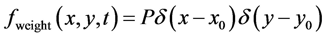
This type of load on a plate corresponds for example to the actions of generators or some robots. Both machines can be regarded as a mass device M, located on the plate by its coordinates . These devices in addition to their own weight per unit area
 , impose at the point
  of the plate, at regular time intervals equal to T, a surface force
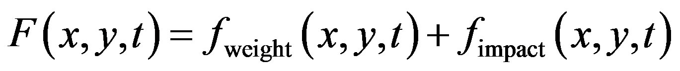
  whose intensity (I) may change over time. So, the external excitation
  is a combination of these two efforts :
 (1)
(1)
where,
 (2)
(2)
 while
while  is defined literally by several models.
In general, the impact force is modelled as a rectangular pulse or as a Gaussian function whose integral over the duration of the impact is equal to the impulse of impact. The duration of the impact depends on the nature of contact between the exciter and the plate, the material they are made off and their dimensions. Therefore, minimizing the impact force is equivalent to minimizing the impulse of impact [19]. The case of rectangular plate is address in this study.
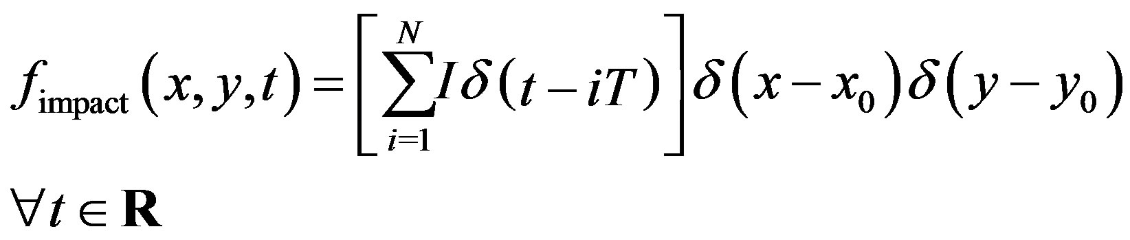
This model of excitation assume a force occurring at regular intervals of time equal to T and can be described as follows:
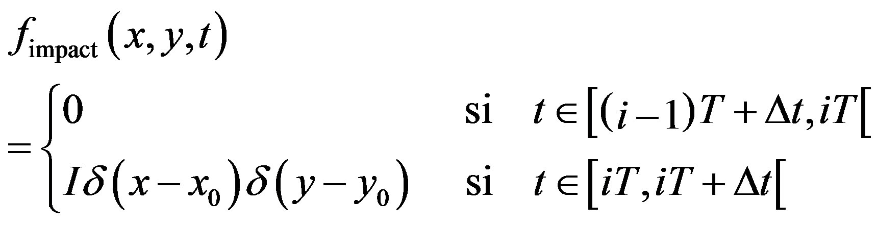 (3)
(3)
with .
.
N stand for the total number of impact while  represents the duration of the pulse.
The presence of the Dirac delta functions  and
and  denote the local character of the impulsive force. If the pulse duration
  becomes too small as to be neglected, this model can be replaced by the model of the Dirac delta function giving by :
 (4)
(4)
2.2. Equations of Motion of the Plate under Control
The main plate (see Figure 1) which is under the same boundary conditions with the dynamic absorbing plate is attached to this one by springs and dampers distributed uniformly (see Ref. [6]).
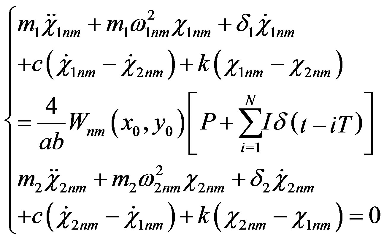
The equations of motion of flexural vibration for the main and dynamic absorbing plates with uniform flexural rigidity and uniform mass per unit area are expressed as
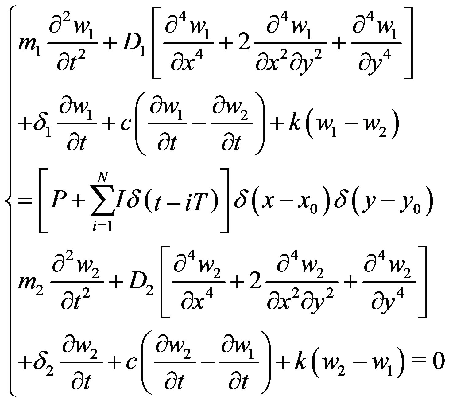 (5)
(5)
where the deflections of the main and dynamic absorbing plates are denoted by  and
and  respectively.
  and
and  are their mass per unit area,
  and
and  their damping coefficients,
  and
and  their flexural rigidity, k and c are the spring constant and the damping coefficient of connecting springs and dampers between the main and dynamic absorbing plates, respectively. I is the intensity of the periodic impulsive load, T the exciting period, P the weight per unit area of the device creating the impulsive load,
  is the Dirac delta function and
  coordinates of the load position.
Let’s denote  and
and  the densities,
  and
and  the thicknesses,
  and
and  the Young’s modulus,
  and
and  the Poisson’s ratios of the main and dynamic absorbing plates respectively. It comes whereas:
 ,
,  ,
,  , and
, and

While taking into account the boundaries conditions, the following approximate functions can be used for the solutions of equations of the system (5):
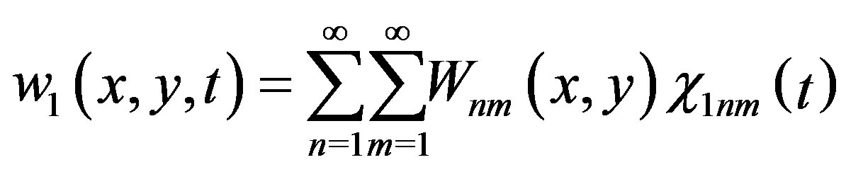 (6)
(6)
 (7)
(7)
in which  and
and  are unknown functions of the time of the main and dynamic absorbing plates respectively and
  the normalized eigenfunction of mode
  of the both plates given by :
 (8)
(8)
 is a natural mode with n and m nodal lines lying the xand y-directions, respectively, including the boundary as the nodal lines. Substituting Equations (7) and (8) into Equation (5), according to the orthogonality of the eigenfunction gives
 (9)
(9)
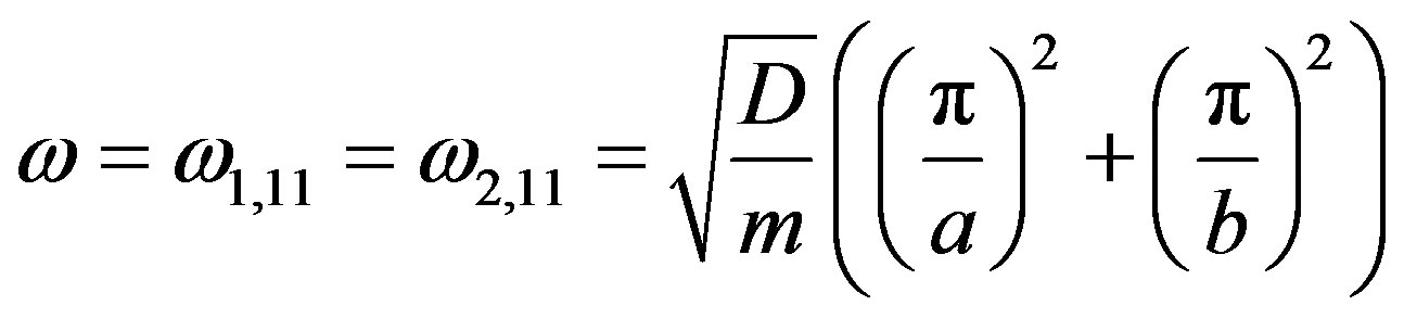
 and
and  are natural frequencies of modes (n,m) of the main and dynamic absorbing plates respectively and are derive as follows:
 (10)
(10)
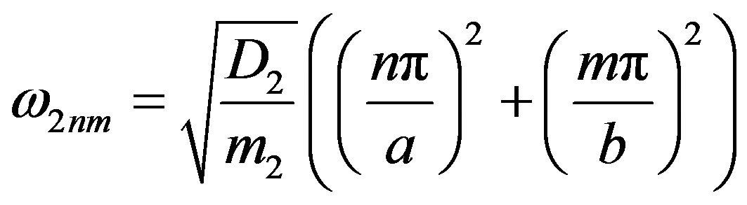 (11)
(11)
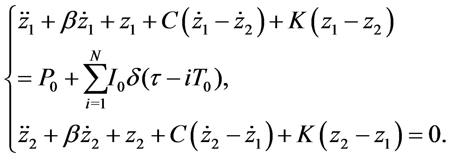
In non dimensional form, Equation (5) becomes,
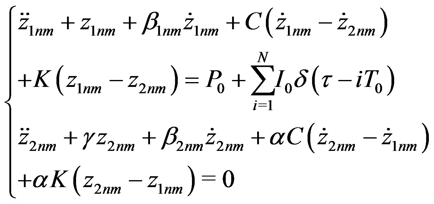 (12)
(12)
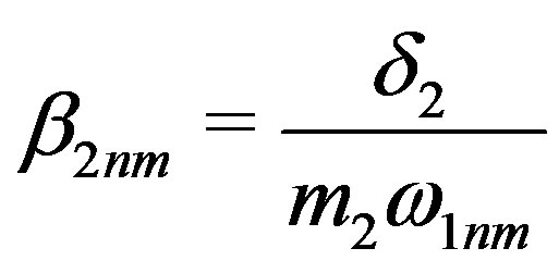
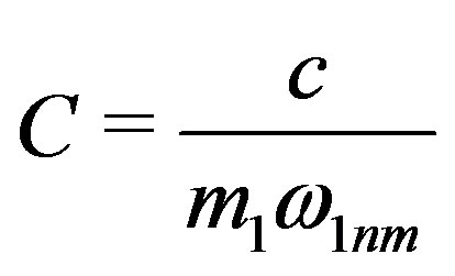
where
 ,
, ;
;
 ,
, ;
; ,
,
 ;
;
 ,
, ;
; ,
,
 ;
; ,
,
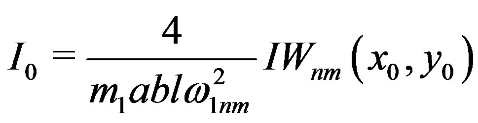
where l a reference length.
3. Analytical Solution of the Modal Equations
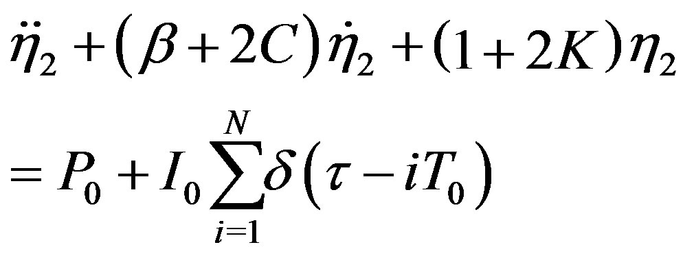
Sine the most path of the energy of the system is embedded in the first mode of vibration, from Equation (9) we then expressed
 (13)
(13)
where
 ;
; ;
;
 ;
;
 ;
;  and
and ;
; 
and ;
;
 and
and
 ;
;  and
and .
.
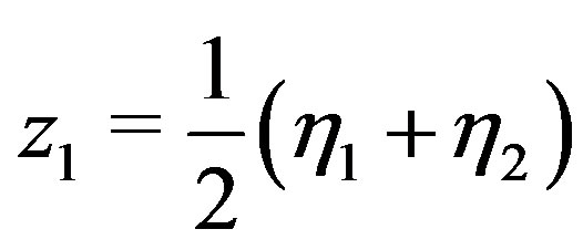
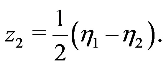
The resolution of Equation (13) is not straightforward. Hence to overcome such a situation, it useful to assume new variables as following:
 (14)
(14)
 (15)
(15)
Adding the two set of Equations (13) gives the following
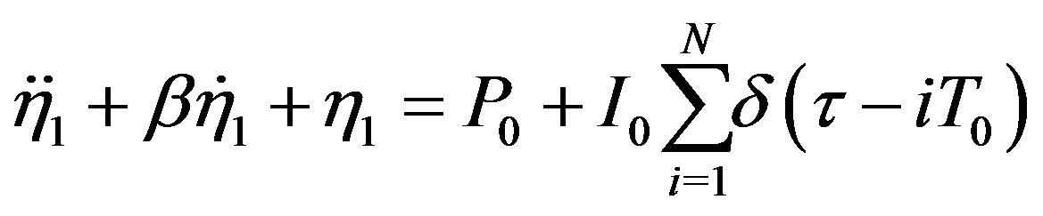 (16)
(16)
Subtracting the two set of Equations (13) yields to the following :
 (17)
(17)
The resolution of the two differential Equations (16) and (17) permits to find the solutions of (13) through the following expressions
 (18)
(18)
 (19)
(19)
Thus, Equations (16) and (17) can be rewritten as follows
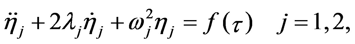 (20)
(20)
where
 ,
, ;
; ,
, 
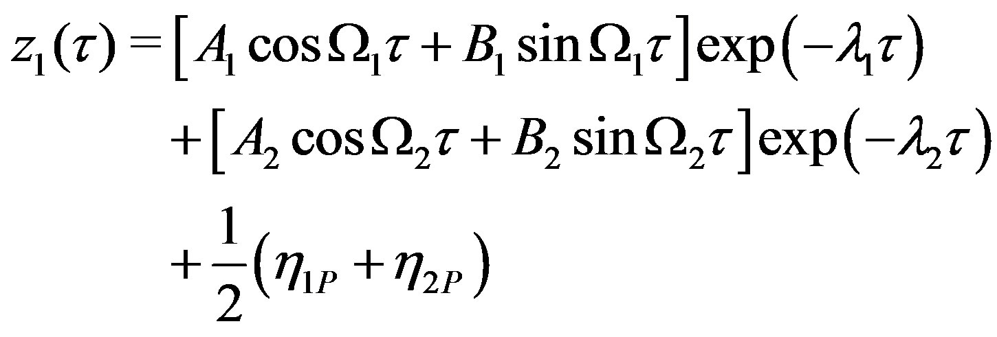
The solutions of Equation (20) are then derived and given by
 (21)
(21)
in which  and
and  represent the constants of integration,
  are the particular solutions of Equation (20), and
  are the vibration frequencies expressed as
 (22)
(22)
The shape of the external excitation  suggests a treatment at intervals in oder to determine the particular solutions
  [20]. So, while considering the realistic case of excitation for which the pulse is not actually instantaneous as advocated by the Dirac delta function, it seems worthy to consider the three following main in order to well characterize the dynamics of the plates.
• Phases I: 
(The dynamics responses are considered between the impacts of order  and
and )
)
Here, ; therefore :
 (23)
(23)
• Phases II: 
(The dynamics response are considered during the impacts of order )
)
Here, one rather has ; so :
 (24)
(24)
• Phase III: 
(The dynamics response are considered after all N impacts)
This phase of the process can be discerned as an element of the first phases for , corresponding to the dynamics of the plates between the impact of order N and the frictional impact of order
 . The particular solutions of this phase are given by Equation (23). Therefore, the solutions
  and
and  are finally obtained and given as
 (25)
(25)
 (26)
(26)
The particular solutions  and
and  are given by expressions (21) according to the state of vibration phase. The constants of integration
 ,
,  ,
,  and
and  are determined by the initial conditions of a current phase of the movement that are different from the final condition of the previous phase. Thus, the knowledge of the initial conditions of the first phase of the movement, that is also the initial conditions of the problem, permits to get closer to those of the other phases and therefore to determine the solutions of the problem at all times.
In the uncontrolled case ( ), it comes the following:


 .
.
The two plates then become uncoupled and the solutions are now given by
 (27)
(27)
 (28)
(28)
in which ,
,  ,
,  and
and  are the new constants of integration.
The control is efficient when the maximum value of  is lower that the one of
 . This criteria enable to foresee the effectiveness of the control strategy.
4. Numerical Analysis
4.1. Validation of the Analytical Results
We compare graphically, the analytical and numerical solutions for several values of parameters of the problem. As an example, we consider the main and dynamic absorbing plates identical made of steel with the following parameters :
Density of material 
Young’s modulus Poisson’s ratios
 Damping coefficient
 Width a = 0.9 mLength b = 1.5 mThickness h = 0.002 m.
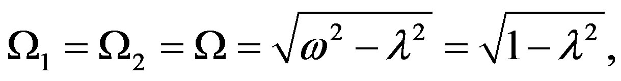
These quantities permit to find the dimensionless parameter  and the free frequencies of the two plates as
 .
.
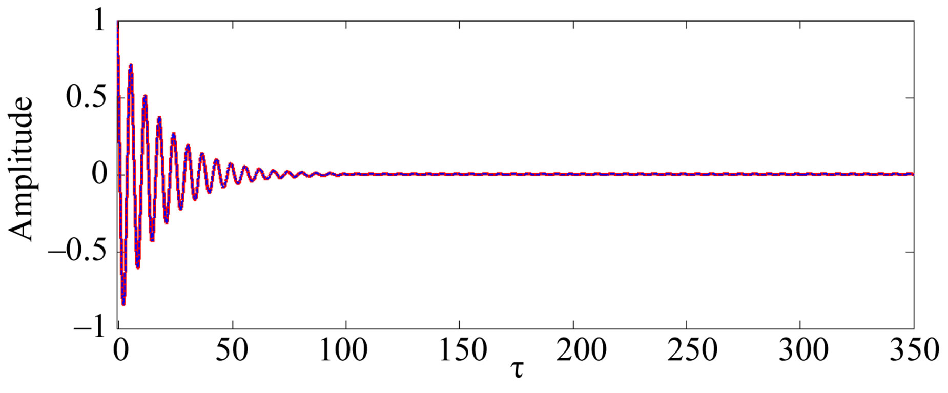
The fourth order Runge Kutta algorithm is used to computed the numerical solutions. Figures 2 and 3 display the time histories of the maximum amplitude of vibration in other to validate the result of analytical investigation. These figures show an excellent agreement between numerical and analytical results. The slight shifts observed for each impact are probably caused by sudden numerical fluctuations due to the discontinuity of the external excitation.
4.2. Enhancement of Control Process
Finding accurate condition that allows optimization of the control strategy is of interest. Thus we have at one’s disposal, several possibilities to choose the type of absorbing plate and among which the following:
• Steel plate:
 ,
, 
• Tungsten plate:
 ,
,  Kg/m3
Kg/m3
• Aluminium Plate (7075): 
 ,
, 
• Concrete plate (E20): 
 ,
, 
• Wood plate (plywood): 
 ,
, 
Each of these plates has thickness  and their coefficients of dissipation
 , chosen such that the dimensionless parameter β2 is always as β2 = β1 = 0.105. The initial conditions and the external force of excitation
 (a)
(a)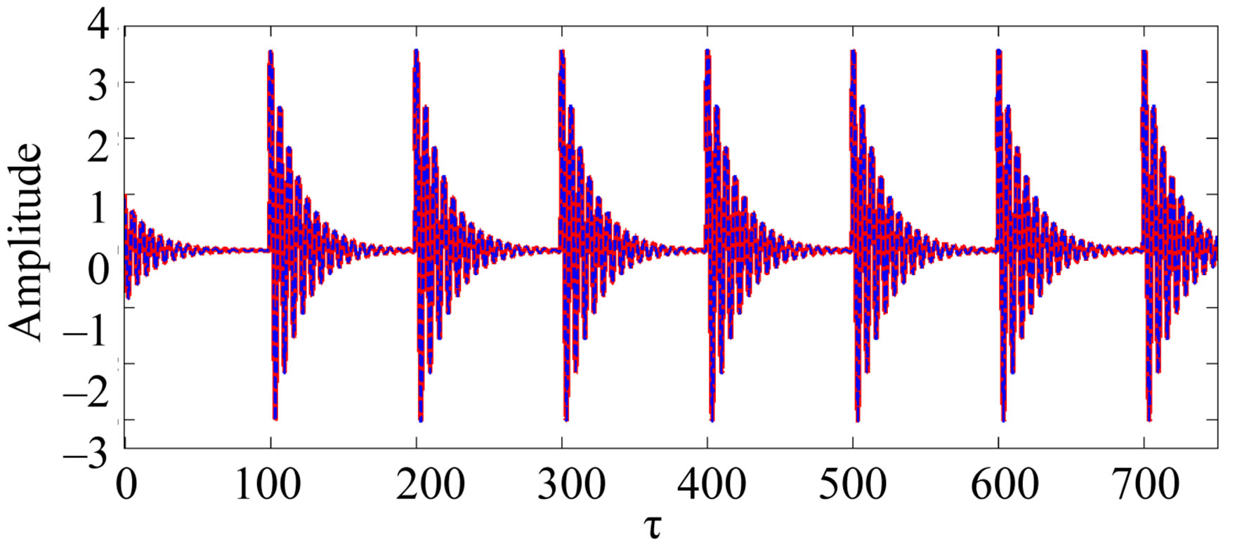 (b)
(b)
Figure 2. Times histories of maximum amplitudes of vibrations: Comparison between the analytical (red line) and numerical (discontinuous blue line) solutions; (a) I0 = 0, P0 = 0; (b) I0 = 4, P0 = 0.
 (a)
(a)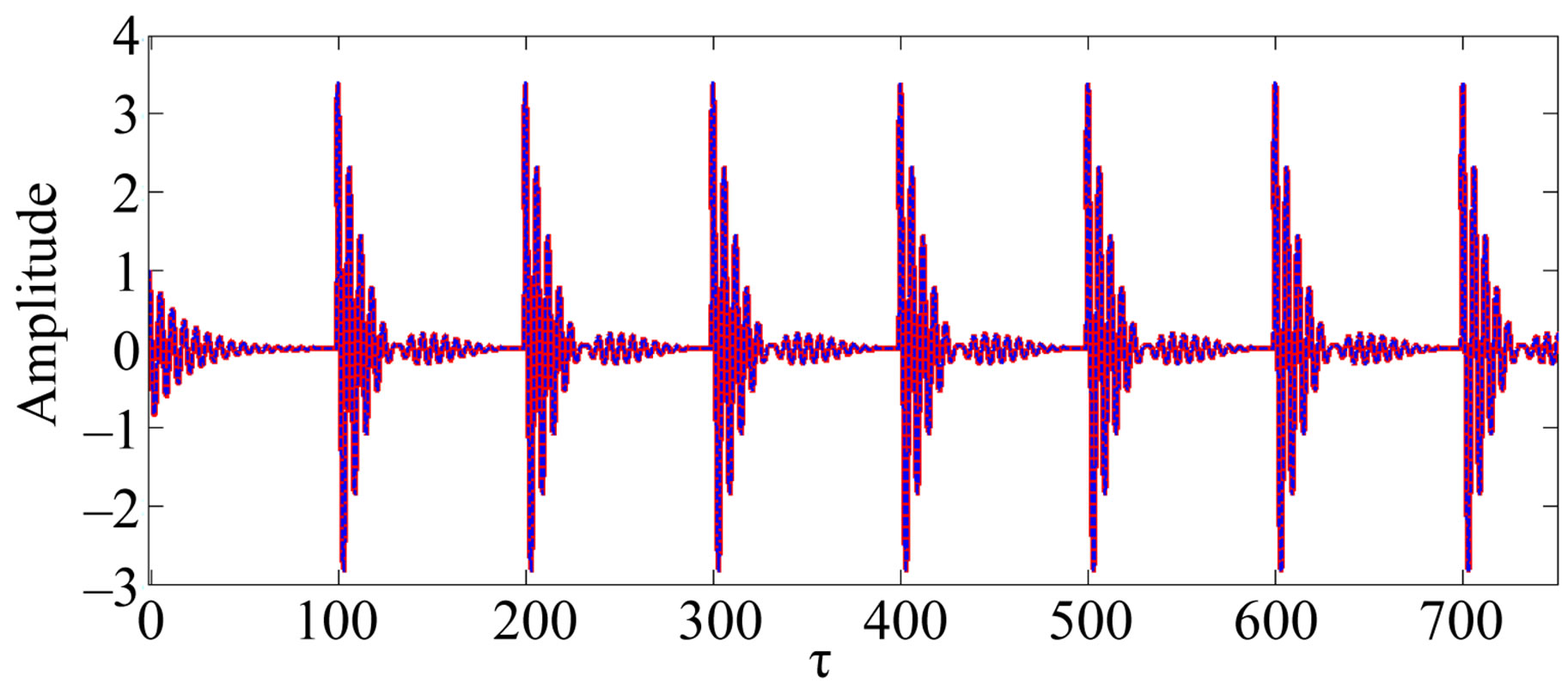 (b)
(b)
Figure 3. Times histories of the maximum amplitude of vibration: Comparison between the analytical (red line) and numerical (discontinuous blue line) solutions for I0 = 4 and P0 = 0; (a) K = 0, C = 0.5; (b) K = 0.1, C = 0.
are the same that in the section (4.1); but with  and
and 
4.2.1. Control Efficiency
The dynamic absorbing plate here is made of steel whose thickness is . The evolution of amplitude plotted in Figure 4 shows that the amplitude of vibration under control is lower than the one without control. Then control is indeed efficient for the control

Figure 4. Times histories of the maximum amplitude of vibration: Comparison between the amplitude responses of the main plate in uncontrolled case (gray line) and in controlled case (black line) for K = 0.1, C = 0.1.
parameters chosen. The possibility of the efficiency of the control being already pointed out for particular values of parameters of control. For that aim, we investigate separately their effects by considering other type plate having different physical characteristics compared to the one studied above.
4.2.2. Effect of the Control Parameters
Here, we analyze how much the nature of absorbing plate impacts the control process. All the absorbing plates used here are taken such that the thickness .
.
1) Effect of viscous coupling
Figure 5 shows that the control is efficient for all values of C since the amplitude of the control system is less than the one of the uncontrolled system (C = 0). This effect is particularly noticeable for higher values of C. In addition, this damping appears to depend on the material of the dynamic absorbing plate, and increases with the Young’s modulus.
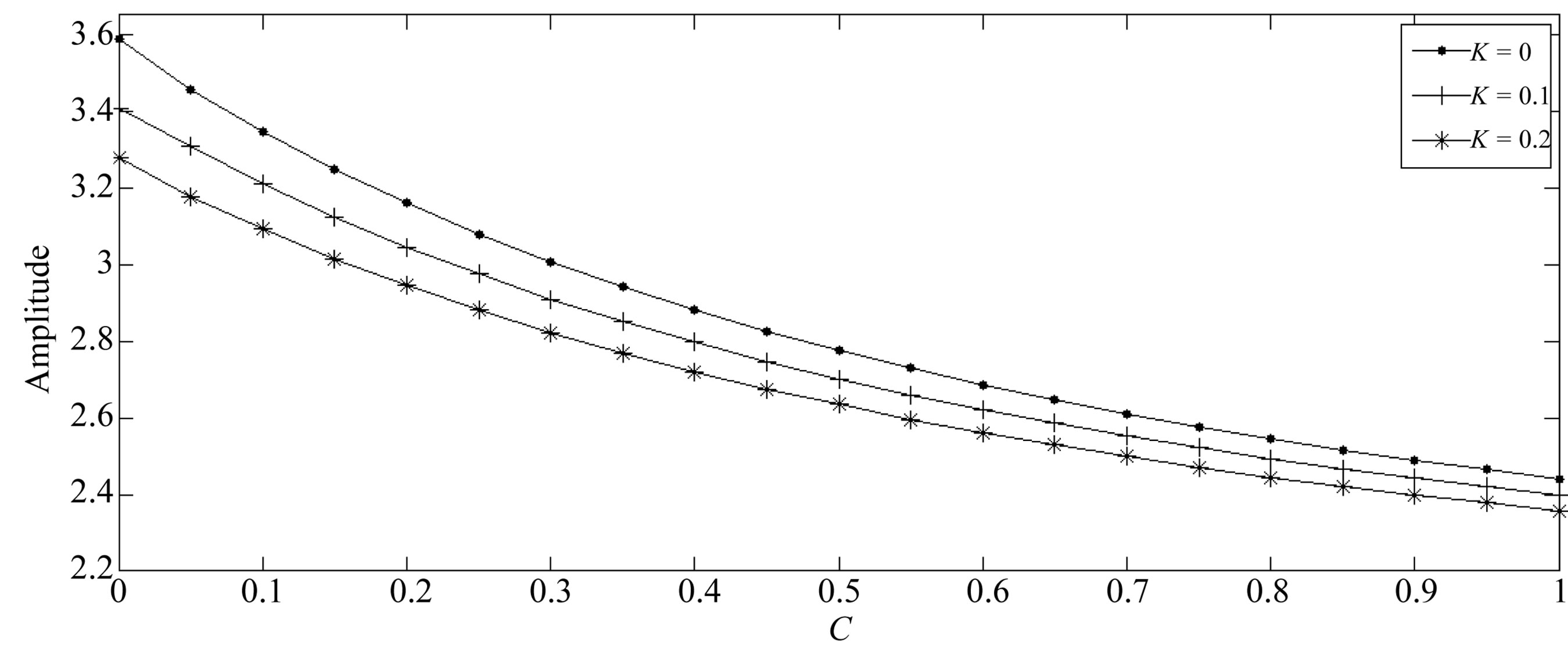
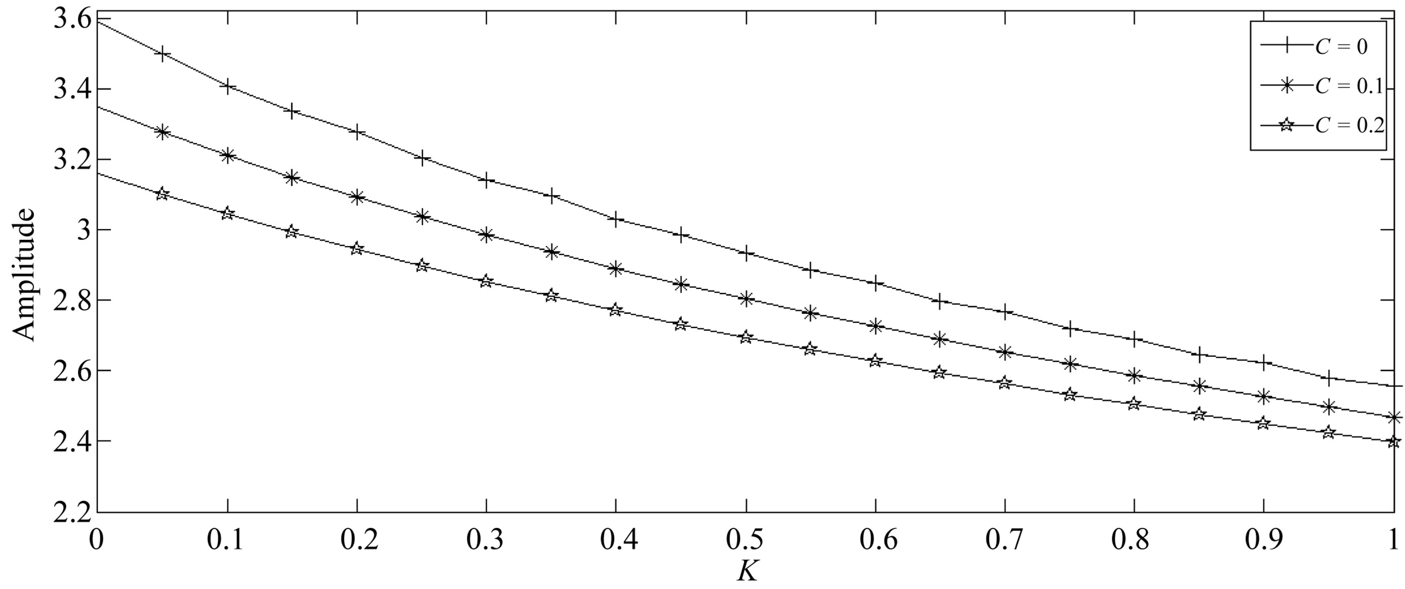
2) Effect of elastic coupling
As shown for the viscous control, the elastic control (see Figure 6" target="_self"> Figure 6) is also efficient for all values of K. Moreover, this efficiency increases as K becomes higher. In general, the absorbing plate made in steel gives more better protections compared to those made wood, concrete and aluminium.
3) Effect of viscoelastic coupling
A generalization shown in Figure 7 reinforce our previous analysis revealing that the amplitudes of the vibrations decrease when the coupling becomes more and more robust. In other words, this happen when the coefficient of dissipation of the shock absorbers and the constant of stiffness of the springs increase.
4.2.3. Effects of the Characteristics of the Dynamic Absorbing Plate
In this subsection, the influences of the thickness and the Young’s modulus of the dynamic absorbing plate on the amplitude of vibrations are investigated.
 (a)
(a)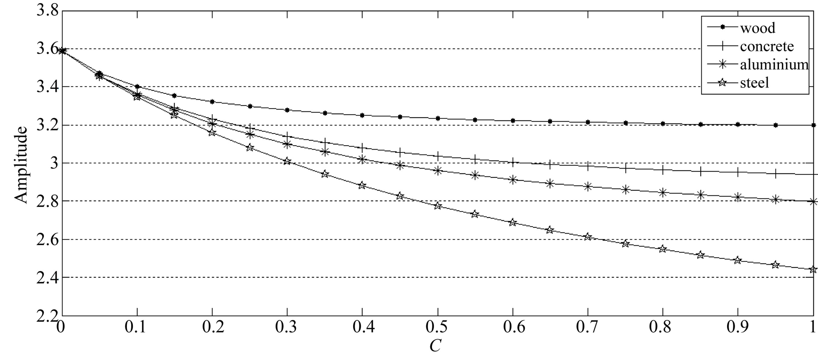 (b)
(b)
Figure 5. Effects of the viscous coupling on the amplitude response of the system: (a) For absorbing plate made of steel; (b) For absorbing plate made of wood, concrete, aluminium and steel.
 (a)
(a)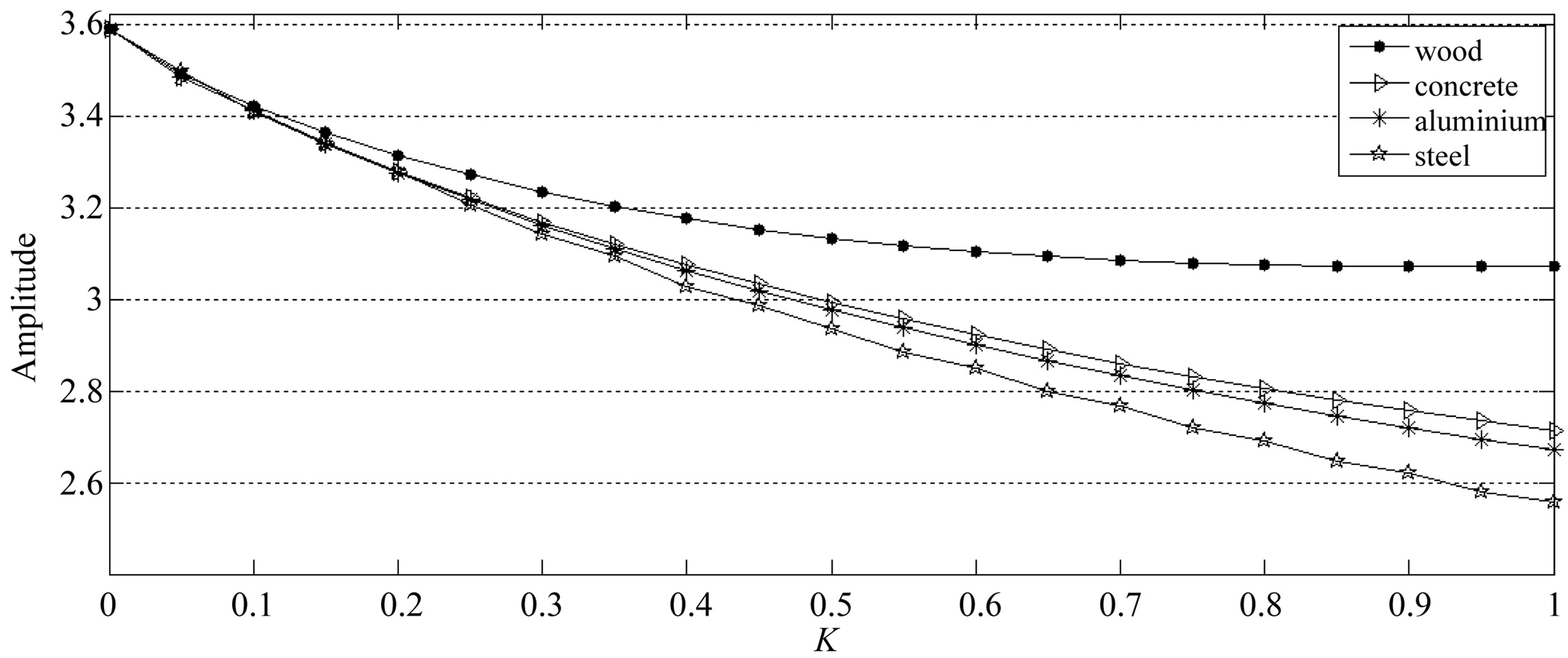 (b)
(b)
Figure 6. Effect of the elastic coupling on the response of the system: (a) For absorbing plate made of steel; (b) For absorbing plate made of wood, concrete, aluminium and steel.
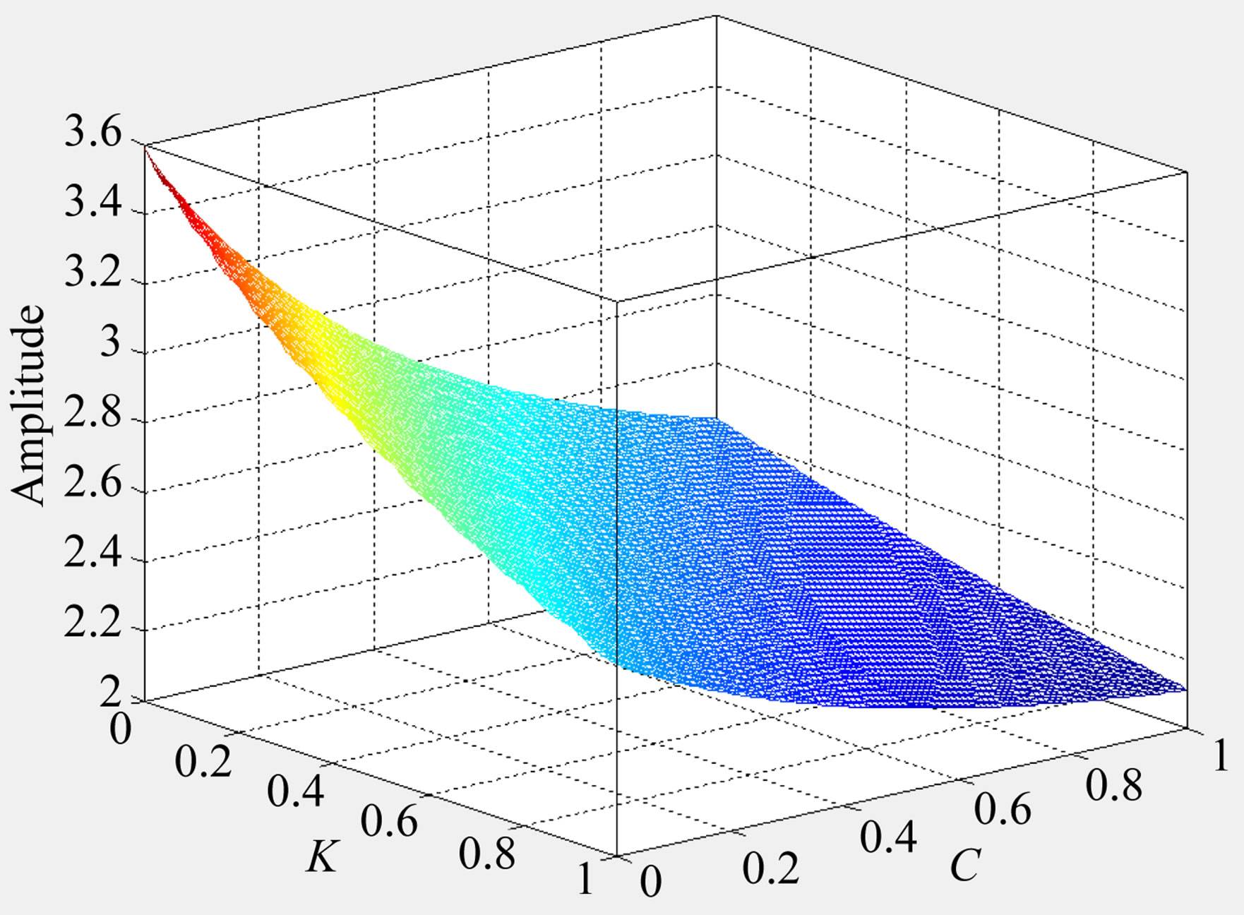
Figure 7. Effects of the viscoelastic coupling on the amplitude response of the system.
From Figure 8 it appears that the vibration amplitudes decrease with the thickness  and Young’s modulus
  of the dynamic absorbing plate and stretches toward an unique limit when
  increases considerably. Furthermore, the curves exhibit peaks for certain values of the ratio
 . The analysis of the position of this peak for the dynamic absorbing plate made in steel for which
 , predicts that such behavior is observed when the vibration frequencies of the two plates are equal. To test this hypothesis as well as the effect of Young’s modulus of dynamic absorbing plate, we plot the evolution of the amplitude of vibration of the main plate according to the vibration frequency of the dynamic absorbing plate for several values of its mass per unit area
  (see Figure 9).
The peak of amplitude occurs when the vibration frequencies are equal. In addition, the amplitude of vibration decreases with the vibration frequency  of the dynamic absorbing plate and with
  for which it has a linear dependency.
4.2.4. Effect of the Position of the Excitation
One interesting situation is the influence of the position of excitation on the main plate. For that aim, it has been plotted as shown in Figure 10, the three dimensional graph representing the maximum amplitude of vibration as function of coordinates position  of external force. It appears generally with and without control that, the amplitudes of vibration gradually decrease when the excitation device goes from the center of the plate to the edges. As a consequence, one way to reduce the amplitude of vibration could be the choice of localize position of the excitation.
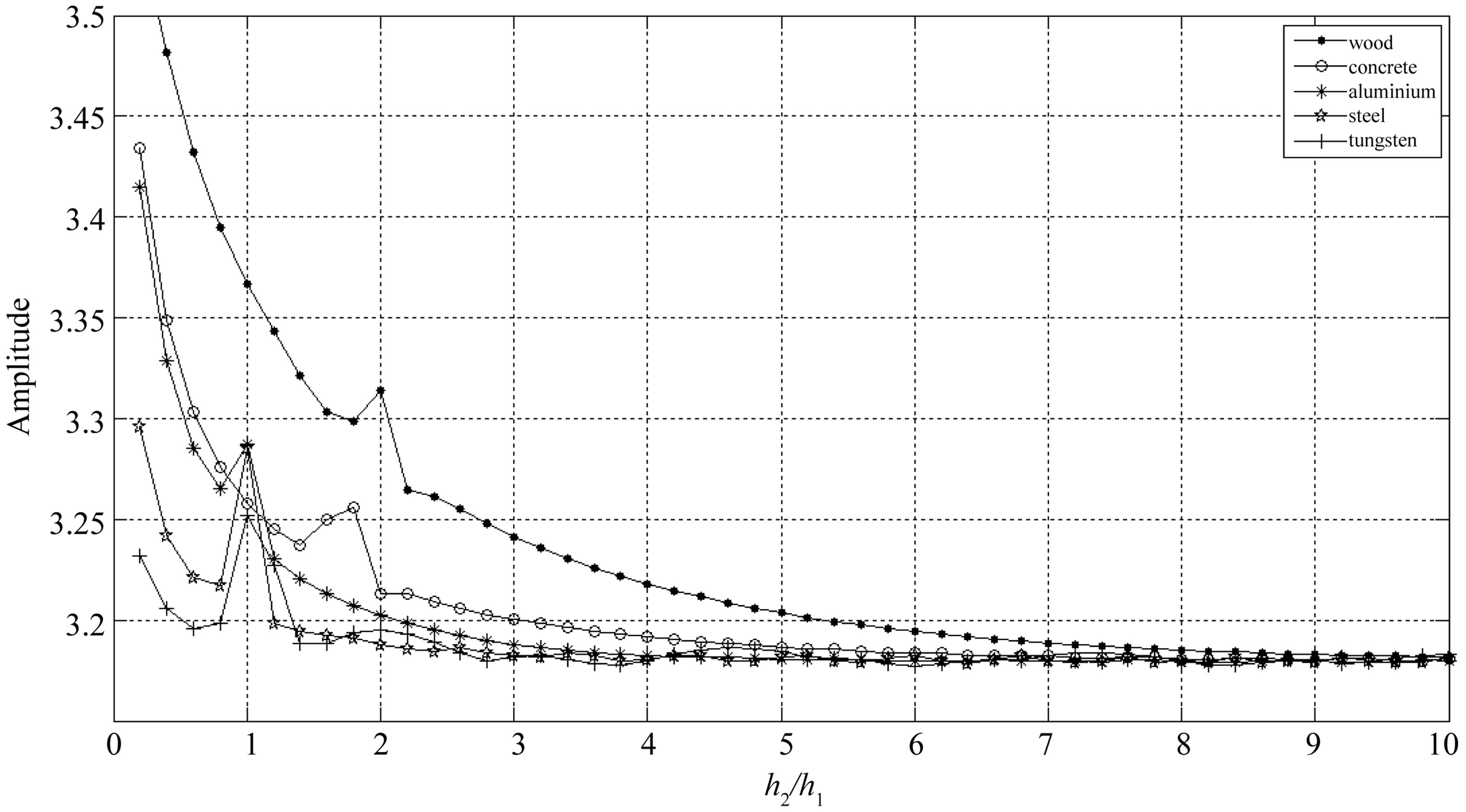
Figure 8. Maximal amplitudes of vibrations versus to the thickness of the dynamic absorbing plates with various characteristics.
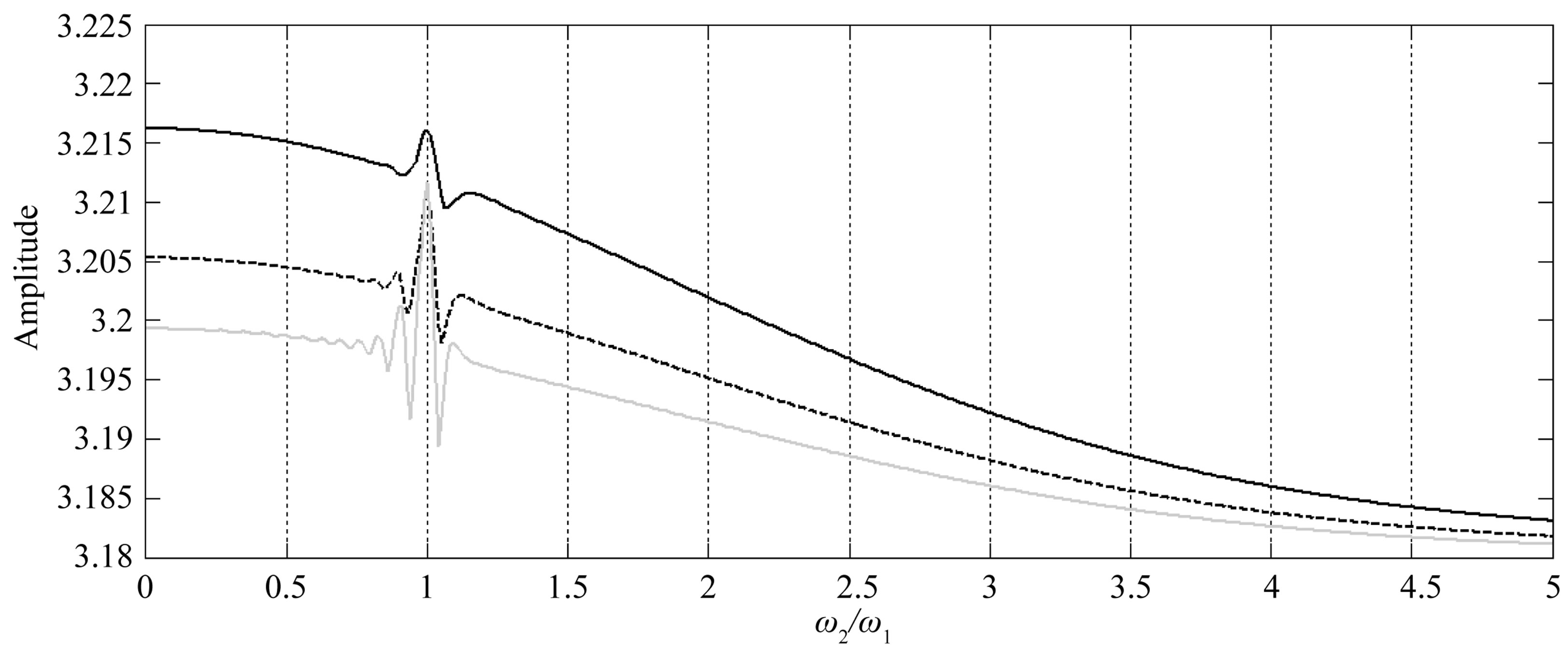
Figure 9. Maximal amplitudes of vibrations versus the frequency of the absorbing plate for m2 < m1 (continuous black line), m2 = m1 (discontinuous black line), m2 > m1 (gray line).
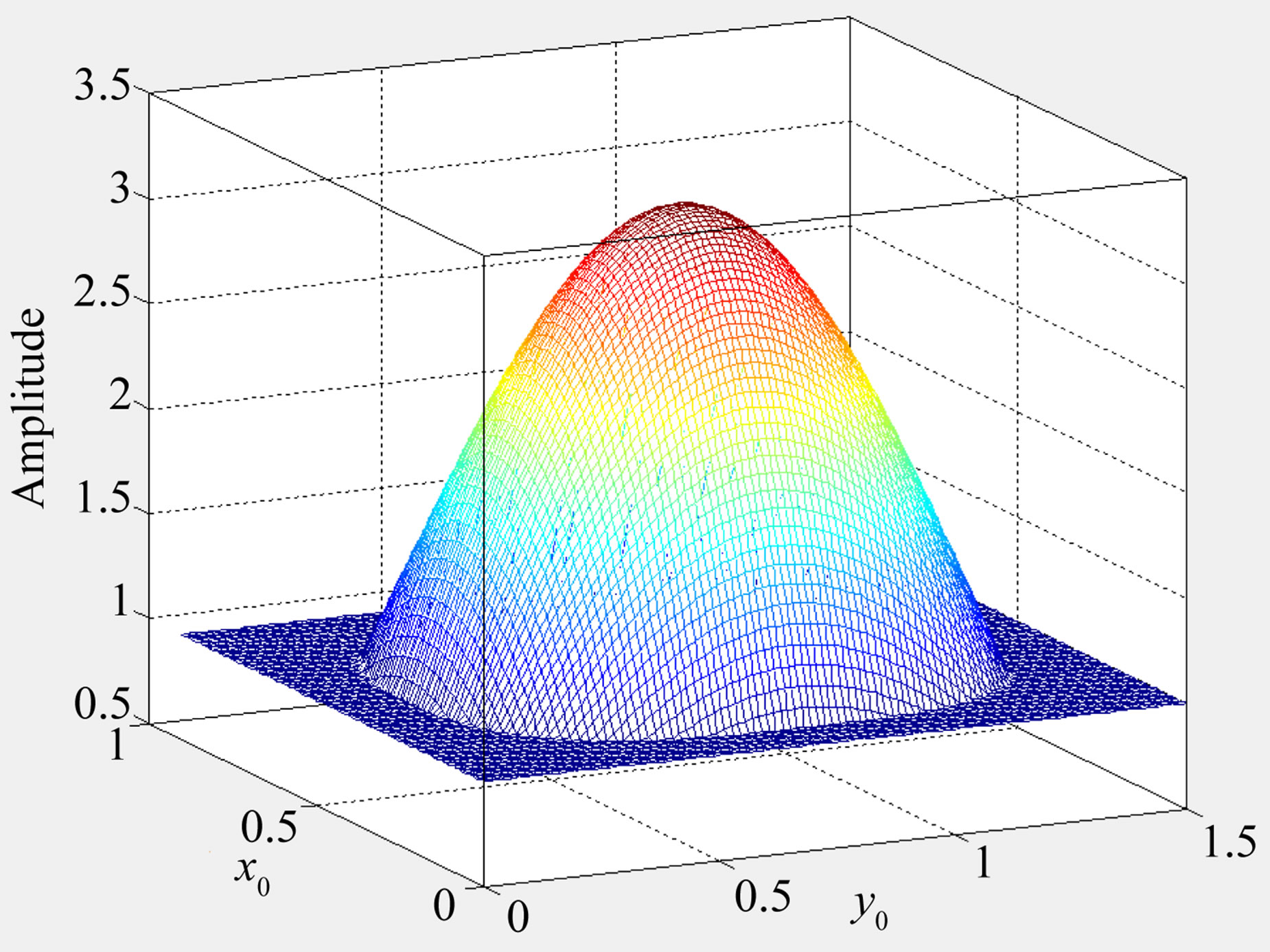
Figure 10. Amplitude of vibrations versus the position of the external forces.
5. Conclusion
The viscoelastic control has been proved to reduce or suppress amplitude of vibration of a rectangular plate under a localized periodic impulsive excitation. We started by modelling the impact force as a rectangular pulse which consider in this form enabled to subsequently model the dynamics of the plate under control for uniform distributions of the viscoelastic coupling. The modal equations derived from this modelling have been solved analytically and verified numerically. Considering the condition for the efficiency of control technics, we found that the control is effective whatever the values of the control parameters chosen. Moreover, the effectiveness of the control increases as the values of the control parameters becomes higher. We have also shown that the frequency of vibration of the dynamic absorbing plate has a positive effect on the control when it is greater than the one of the main plate. Regarding the effect of external excitation location on the plate, we have found that this position has particular effects on the intensities of amplitude of vibration and could influence considerably the dynamics response of the system.
6. Acknowledgements
Part of this work was completed during a research visit of Dr Nana Nbendjo at the Steel and Composite Structures Team of the University of Kassel in Germany. He is grateful to TWAS (The Academy of Science for the Developing World) and DFG (German Research Foundation) for financial support.
REFERENCES
- T. T. Song and W. F. Chen, “Active Structural Control: Theory and Practice,” Wiley, New York, 1990.
- C. R. Fuller, S. J. Eliot and P. A. Nelson, “Active Control of Vibration,” Academic Press, London, 1997.
- S. H. Kim, S. B. Choi, S. R. Hang and M. S. Han, “Vibration Control of Fexible Structure Using a Hybrid Mounts,” International Journal of Mechanical Sciences, Vol. 46, No. 1, 2004, pp. 143-157. doi:10.1016/j.ijmecsci.2004.02.011
- L. Jezequel, “Active Control in Mechanical Engineering,” Hermes, New Castle, 1995.
- B. R. Nana Nbendjo and P. Woafo, “Modelling, Control by Sandwich of the Dynamics and Optimization in a Strongly Nonlinear Beam,” Far East Journal of Dynamical Systems, Vol. 8, 2006, pp. 267-283.
- T. Aida, K. Kawazoe and S. Toda, “Vibration Control of Plates by Plate-Type Dynamics Vibration Absorber,” Journal of Vibration and Acoustics, Vol. 117, No. 3, 1995, pp. 332-338. doi:10.1115/1.2874455
- T. Aida, S. Toda, S. N. Ogowa and Y. Simada, “Vibration Control of Beams by Beam Type Dynamics Vibrations Absorber,” ASCE Journal of Engineering Mechanics, Vol. 118, No. 2, 1992, pp. 163-175. doi:10.1061/(ASCE)0733-9399(1992)118:2(248)
- B. R. Nana Nbendjo and P. Woafo, “Modeling and Optimal Active Control with Delay of the Dynamics of a Strongly Nonlinear Beam,” Journal of Advanced Research in Dynamical and Control Systems, Vol. 1, 2009, pp. 57-74.
- C. A. Kitio Kwuimy, B. R. Nana Nbendjo and P. Woafo, “Optimization of Electromechanical Control of Beam Dynamics: Analytical Method and Finite Differences Simulation,” Journal of Sound and Vibration, Vol. 298, No. 1-2, 2006, pp. 180-193. doi:10.1016/j.jsv.2006.05.019
- A. A. Nanha Djanan, B. R. Nana Nbendjo and P. Woafo, “Control of Vibration on a Hinged-Hinged Beam under a Non-Ideal Excitation Using RLC Circuit with Variable Capacitance,” Nonlinear Dynamics, Vol. 63, No. 3, 2011, pp. 477-489. doi:10.1007/s11071-010-9816-1
- J. L. P. Felix and J. M. Balthazar, “Comments on a Nonlinear and Non-Ideal Electromechanical Damping Vibration Absorber, Sommerfeld Effect and Energy Transfer,” Nonlinear Dynamics, Vol. 55, No. 1-2, 2009, pp. 1-11. doi:10.1007/s11071-008-9340-8
- R. A. Morgan and R. W. Wang, “An Active Passive Piezoelectric Absorber for Structural Vibration Control under Harmonic Excitations with Time-Varying Frequency, part1: Algorithm Development and Analysis,” Journal of Vibration and Acoustics, Vol. 124, No. 1, 2002, pp. 77-83. doi:10.1115/1.1419201
- M. S. Tsai and K. W. Wang, “On the Structural Damping Characteristics of Active Piezoelectric Actuator with Passive Shunt,” Journal of Sound and Vibration, Vol. 221, No. 1, 1999, pp. 1-22. doi:10.1006/jsvi.1998.1841
- I. Bica, “Damper with Magnetorheological Suspension,” Journal of Magnetism and Magnetic Materials, Vol. 241, No. 2-3, 2002, pp. 196-200. doi:10.1016/S0304-8853(02)00009-4
- B. Liu and H. S. Tzou, “Distributed Photostrictive Actuator and Optopiezothermoelasticity Applied to Vibration Control of Plates,” Journal of Vibration and Acoustics, Vol. 120, No. 4, 1998, pp. 936-943. doi:10.1115/1.2893923
- H.-R. Shih, H.-S. Tzou and M. Saypuri, “Structural Vibration Control Using Spacially, Configured Opto-Electromechanical Actuators,” Journal of Sound and Vibration, Vol. 284, No. 1-2, 2005, pp. 361-378. doi:10.1016/j.jsv.2004.06.013
- Q. Zhang and B. Z. Guo, “Stabilization of an Elastic Plate with Viscoelastic Boundary Conditions,” Journal of Optimization Theory and Application, Vol. 122, No. 3, 2004, pp. 669-690. doi:10.1023/B:JOTA.0000042600.95607.f9
- H. P. Niu, Y. H. Zhang, X. H. Zhang and S. L. Xie, “Active Vibration Control of Plates Using Electro-Magnetic Constrained Layer Damping,” International Journal of Applied Electromagnetics and Mechanics, Vol. 33, No. 1, 2010, pp. 831-837.
- S. Lenci and G. Rega, “Periodic Solutions and Bifurcations in an Impact Inverted Pendulum under Impulsive Excitation,” Chaos, Solitons and Fractals, Vol. 11, No. 15, 2000, pp. 2453-2472. doi:10.1016/S0960-0779(00)00030-8
- D. Zwillinger, “Handbook of Differential Equations,” 3rd Edition, Academic Press, Cambridge, 1997.
NOTES
*Corresponding author.