World Journal of Nano Science and Engineering
Vol.4 No.1(2014), Article ID:43742,5 pages DOI:10.4236/wjnse.2014.41003
High Performance Polymer Light-Emitting Devices
Vivek Kant Jogi
School of Studies in Electronics, Pt. Ravi Shankar Shukla University, Raipur, India
Email: vivekkantjogi@gmail.com
Copyright © 2014 by author and Scientific Research Publishing Inc.
This work is licensed under the Creative Commons Attribution International License (CC BY).
http://creativecommons.org/licenses/by/4.0/


Received 24 October 2013; revised 25 November 2013; accepted 2 December 2013
Abstract
In order to improve the performance of polymer light-emitting devices, driving voltages, current efficiency, luminance and power efficiency of different cathode metals such as Ca/Al, CsF/Al, LiF/Al and LiF/Ca/Ag were compared. The results show that cathode metals CsF/Al contain the highest current efficiency, maximum luminance and power efficiency. Therefore, we can choose the CsF/Al to be the cathode for improving the performance of polymer light-emitting devices.
Keywords
PLED; Current Efficiency; Power Efficiency; Current Density

1. Introduction
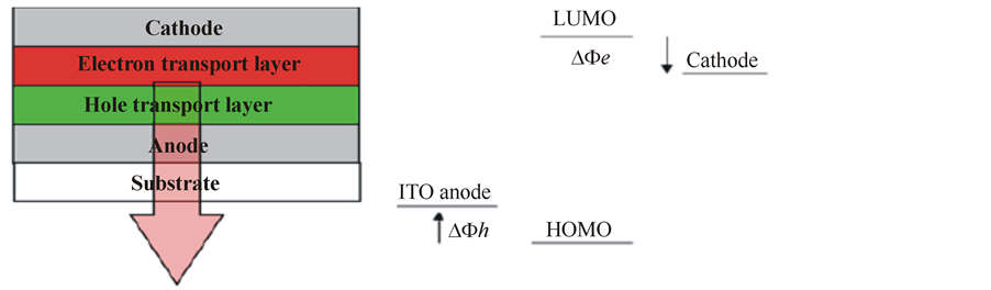
A PLED consists of very thin layers of polymer films sandwiched by two electrodes [1] . In a typical PLED structure, there are two polymer layers, one of which functions as the hole transporting layer and the other functions as the light-emission layer as shown in Figure 1(a). An indium tin oxide (ITO) layer is generally used as the transparent anode, which allows the light generated within the diode to leave the device [1] . The metal cathode is conveniently deposited on top of the polymer by thermal evaporation [1] . The devices’ performance strongly depends on effective charge injection from the electrodes to the organic medium and charge transport in the organic materials.
In an ideal physical process in which the chemical reactions at the interface are ignored, the energy diagram can be represented as shown in Figure 1(b). Here ΔΦh and ΔΦe respectively define the energy barriers for holes and electrons by the Mott-Schottky rule of vacuum level alignment [2] . Although this picture is simple and ideal for the interfacial effect on charge injection, it can nevertheless be successfully used to evaluate the metal electrode’s work functions and the positions of the HOMO and the LUMO of the polymer.
 (a) (b)
2. Devices Fabrication Characteristic
Commercial available indium-tin oxide (ITO) from Sigma Aldrich is used as anode of the PLEDs because of its not only transparent but also high conductivity. Besides, its ionization potential is just about 4.8 eV that is easy to transport the holes into the PEDOT (HTL) layer. The ITO glass obtains 30 Ω/□ resistances. Moreover, it was rinsed by the de-ionized water for removing the dusts & the other particles on the surface and baked at about 120˚C for an hour to evaporate the water vapor. After that, the UV-ozone treatment was used to enrich the oxygen and reduce the oxygen vacancies. That can improve the conductivity of the ITO layer for helping the transport of hole easily [3] .
The poly (3,4-ethylene dioxythiophene), PEDOT solution was spin-coated onto the ITO layer at about 20 seconds. Control the spinning speed of the spin-coating machine is of importance. The first 5 seconds must use a slow spinning speed about 400 rpm after that the spinning speed wasturned to 2000 rpm to provide the homogeneous and high quality layer. Finally, the PEDOT layer was dried by the infrared lamp. The electron transport layer and emissive layer was spin coated by the poly (9,9-dioctylfluorene) (PFO) solution below 400 rpm spinning speed at the first 5 seconds to control the homogeneous layer. Then, the spinning speed of the spin-coating machine was increased to 1000 rpm for 40 seconds and baked by the infra-red lamp for the evaporating minimum 10 minutes.
For deposition of the metal cathode the thermal evaporation machine (Vacuum coating systems Model 12A4D) is used to deposit the thin-film metal layers on the dried PFO layer with the deposition rate of 1.5 nm/s. During the deposition, the pressure of the chamber must need to be controlled to about 5 × 10⁻⁶ mbar for the successful thermal evaporation. Besides, the thickness of thin metal layers is 100 nm each (involving the protective metal layer).The different fabricated specimens are
Device A: ITO/PEDOT/PFO/Ca/Al,
Device B: ITO/PEDOT/PFO/CsF/Al,
Device C: ITO/PEDOT/PFO/LiF/Al,
Device D: ITO/PEDOT/PFO/LiF/Ca/Ag.
The current, voltage, luminance and electroluminescence (EL) of the devices are measured using spectrophotometer.
3. Results and Discussion
PFO layer was used to be the emissive layer so the EL spectrums of these four devices have two blue emission peaks that are 440 nm and 460 nm. Figures 2-5 show the comparison of luminance vs. voltage, Current Efficiency, Power Efficiency and Current Density of Device A, B, C and D respectively.
From Figure 2, Device A (Blue) like to tend in steady that mean it would not have a higher amount luminance appear even though the voltage was increased. Device C (Purple) initial luminance occurred at the about 3.6 V which is higher than other specimens as well as it also tendentious to steady so it maximum luminance would not be higher and its power consumption is the largest. The Device B (Red) is the best performance compared with the other curves. Device B (Red) achieved the higher luminance at the lower voltages. For example, if the designed luminance is 700 cd/m2, the driving voltage of CsF/Al just 6.5 V. Comparing with the other
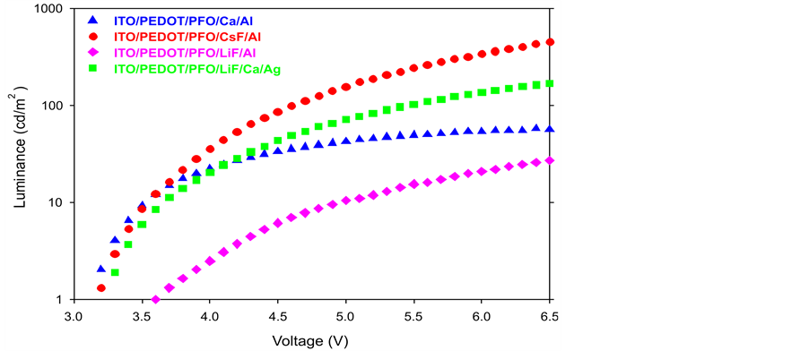
Figure 2. Comparison of luminance vs. voltage.
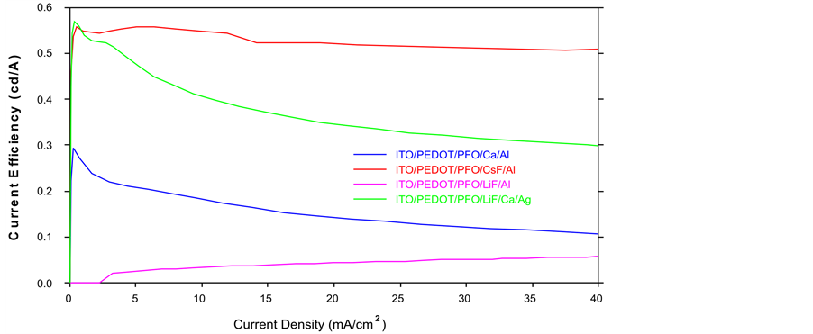
Figure 3. Comparison of current efficiency.
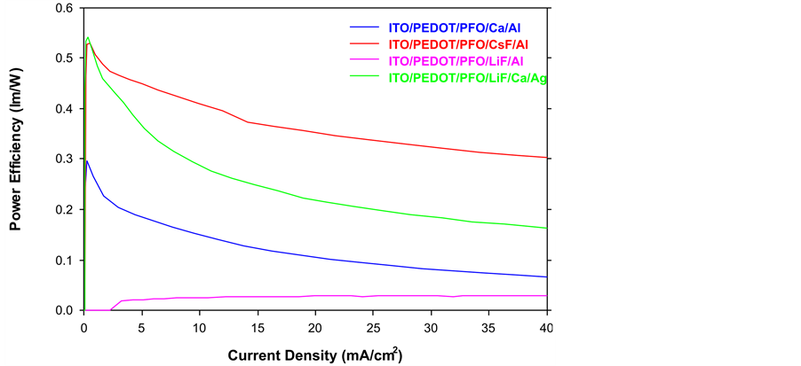
Figure 4. Comparison of power efficiency.
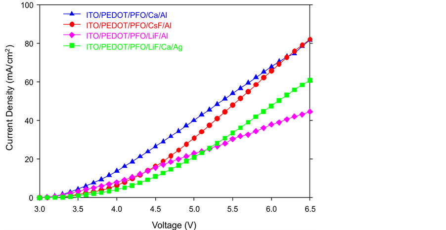
Figure 5. Comparison of current density.
specimens, the maximum luminance at the same voltage of CsF/Al is the highest. Therefore, we can reduce the driving voltage and increase the luminance through the changing the cathode materials such as LiF/Ca/Ag or CsF/Al. From Figure 3, only the Device B (Red) (CsF/Al) keeps steady, which is the most stable curve out of these four specimens. Furthermore, CsF/Al also is the highest curve of the graph that means it has the highest current efficiency. For example, if the current density is 40 mA/cm2, the current efficiency of CsF/Al is 0.51 cd/A which is the highest one mean it has lowest power consumption. Therefore CsF/Al and LiF/Al are the lowest and highest power consumption respectively. From Figure 4, when the current density is 40 mA/cm2, the power efficiency of CsF/Al is 0.3 lm/W which is highest. The power efficiency of CsF/Al and LiF/Ca/Ag are the better choice of the cathode for providing the higher power efficiency and lower power consumption of PLEDs. From Figure 5, Device B (Red) CsF/Al has the most of rapid increases, achieved the highest level of current density. For example, when the applied voltage is 6.5 V, the CsF/Al curve can achieve the highest current density 8.2 mA/cm2. It expresses that CsF/Al can generate the highest brightness when the driving voltage is 6.5 V. Besides, its curve increases rapidly that mean it is easy to achieve the designed brightness level. Therefore, it is high sensitive and low reaction time lap. Comparison of the total performance of these four specimens from Table 1, we got the results that CsF/Al is the best materials because it’s performance such as the best of current efficiency, power efficiency, current density and maximum luminance. That means, it does not only provide the higher luminance with lower driving voltage but also reduce the power consumption. Furthermore, CsF/Al is easy to achieve the turn on voltage to provide the luminance quickly due to its properties of current density (low reaction time lap). By the consideration of the above factors, LiF/Ca/Ag also can be used to replace the Ca/Al as a cathode of PLEDs though its performance is worse than CsF/Al. Compared with the normal materials (Ca/Al); LiF/Ca/Ag really has a large improvement. Besides, the LiF/Al is the worst specimens out of the other three samples.

4. Conclusion
In order to improve PLED performance, multi-layer structures were studied. Four types of cathode materials were tested and compared. Those are Ca/Al, CsF/Al, LiF/Al and LiF/Ca/Ag. Lower work function is good for the electron injection from the cathode to emissive layer, so the cathode should be low work function. By comparison of those four specimens, LiF/Al has the worst performance, and CsF/Al has the best performance out of the other specimens. The cathode materials can be replaced by the CsF/Al to achieve lower power consumption, driving voltage and turn-on voltage. Moreover, CsF/Al does not only increase the devices’ luminance

Table 1. Total performance of the devices.
but also reduce the response time lap. As the supporting results of this research, the total performance of the PLEDs can be improved by selecting the appropriate cathode materials as CsF/Al.
References
- Deng, X.-Y. (2011) Light-Emitting Devices with Conjugated Polymers. International Journal of Molecular Sciences, 12, 1575-1594. http://dx.doi.org/10.3390/ijms12031575
- Pope, M. and Swenberg, C.E. (1982) Electronic Processes in Organic Crystals and Polymers. Oxford University Press, New York.
- Bernius, M.T., Inbasekaran, M., O’Brien, J. and Wu, W.S. (2000) Progress with Light-Emitting Polymers. Advanced Materials, 12, 1737-1750. http://dx.doi.org/10.1109/9.402235