International Journal of Geosciences
Vol.5 No.9(2014), Article
ID:48939,17
pages
DOI:10.4236/ijg.2014.59079
Analytical and Numerical Study of the Reflection/Transmission Coefficients in Slight Viscoelastic Medium
Fateh Bouchaala1, Claude Guennou2
1Petroleum Institute of Abu-Dhabi, Abu Dhabi, UAE
2Domaines Oceaniques Laboratory, Brest, France
Email: fbouchaala@pi.ac.ae
Copyright © 2014 by authors and Scientific Research Publishing Inc.
This work is licensed under the Creative Commons Attribution International License (CC BY).
http://creativecommons.org/licenses/by/4.0/


Received 29 March 2014; revised 25 April 2014; accepted 18 May 2014
ABSTRACT
The study done in this paper brings out the effect of the viscoelasticity on the reflection/transmission coefficients. The knowledge of this effect can be useful for several applications, such as enhancing the resolution of the seismic sections, fluid and fracture detection. It can also have other applications different from the geophysical domain, as the study of the bonding between the materials in the civil engineering domain. We use the complex Lame coefficients in the continuity equations at the boundary layers to get the analytical expressions of the reflection/transmission coefficients in viscoelastic media. The coefficients can be divided into two parts, the first part is independent from the quality factor, and it corresponds to the elastic reflection/transmission coefficients. The second part is dependent on the quality factor contrast and it represents the contribution of the viscoelasticity on the reflection/transmission coefficients. From the numerical study it appears that the effect of the viscoelasticity is significant near to the critical angles. This effect is not clear and it is difficult to interpret and we do not know if it has a physical meaning or it is only a mathematical artifact that is why it is better to be far from the critical angles for seismic investigation.
Keywords:Viscoelasticity, Quality Factor, Reflection/Transmission

1. Introduction
The estimation of the reflection/transmission coefficients of the seismic waves is paramount for the investigation of the natural medium and to know their geometrical proprieties. In a perfect elastic medium, these coefficients are computed from the impedance contrast between two neighbouring layers [1] -[3] . In the viscoelastic media in addition to the impedance contrast, the viscoelasticity contrast between the two neighbouring layers should be taken into account. Usually the viscoelasticity of the medium is quantified by using the quality factor , which is inversely proportional to the energy loss
 of the seismic wave:
 (1)
(1)
Buchen [4] has studied the propagation of the seismic wave SH in a layered and slight viscoelastic media. He used complex wave number to compute the reflection/transmission coefficients; the imaginary part of the wave number takes account the viscoelastic functionality. He noted that the difference between the reflection/transmission coefficients in the elastic and viscoelastic media is important when the quality factor contrast between two neighbouring layers is significant. Krebes [5] , has done the same study as Buchen [4] , but he considered the medium was highly viscoelastic. He noted that even by considering the medium highly viscoelastic, the equality of the quality factor between two neighbouring layers implies the independence of the reflection/transmission coefficients from the viscosity of the medium. The results of Buchen and Krebes, were confirmed by Carcione [6] , who studied also the effect of the anisotropy on the reflection/transmission coefficients.
In this paper, first we do an analytical study of the reflection/transmission coefficients in the slight viscoelastic medium. From this study we provide the analytical expressions of these coefficients for all possible incident wave (SH, P and SV), which allows to see clearly the contribution of the viscoelasticity on the reflection/ transmission coefficients. This analytical study is followed by a numerical example; through it we apply the analytical expressions on synthetic data. So far no study about the reflection/transmission coefficients in slight viscoelastic media has been more complete than this one.
2. Analytical Study
Reflection/transmission of plane seismic waves is a local phenomenon, involving local physical proprieties of two medium (1) and (2) at the discontinuity point . Locally, in the vicinity of the point
 , we can consider that the interface is plane and having normal
![]() (Figure 1). At the point
(Figure 1). At the point
 the seismic energy can be divided on reflected and transmitted, and it can generate two waves: reflected and transmitted.
An incident P wave as an incident SV wave can generate reflected P or SV wave and transmitted P or SV wave. However, an incident SH wave can generates only reflected or transmitted SH wave. The reflected or transmitted waves which are different from the incident wave, they are called converted waves, such P-SV reflection for example.
In this study the incident wave is indicated by the subscript![]() , the reflected wave by the subscript
, the reflected wave by the subscript
 and the transmitted wave by the subscript
 . The viscoelastic reflection/transmission coefficient are designed by the variables
 .
.
In this section we put just the main equations leading to the
 coefficients. More details are given in the thesis of Bouchaala [7] .
3. Displacement Continuity
The displacement of the wave particles at the instant
 and the position
 can be expressed as [8] ,
 (2)
(2)
where
![]() is the source term,
is the source term,
 is the circular frequency,
![]() is the amplitude vector at the position
is the amplitude vector at the position . In the orthonormal basis
![]() (Figure 2) the amplitude vector
(Figure 2) the amplitude vector
![]() has the components
has the components
![]() and can be written as,
and can be written as,
![]() (3)
(3)
![]() is the slowness, which can be computed from the velocity
is the slowness, which can be computed from the velocity![]() , the propagation direction
, the propagation direction
 and the quality factor
 by:
by:

Figure 1. Incident, reflected and transmitted waves in a medium composed from two layers (1) and (2), I is the intersection point between the incident wave and the interface, N is the unit vector normal to the interface at the point I.
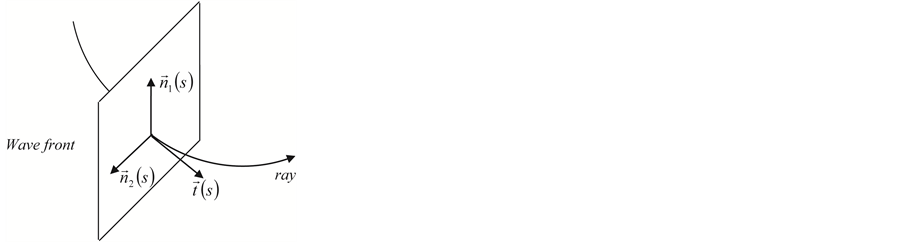
Figure 2. The direct orthonormal basis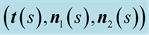 . The unit vector
 is the first Fresnel vector, tangent to the ray, the unit vectors,
 and
and
 are orthogonal between themselves.
 (4)
(4)
In the elastic case the slowness vector is real and independent form ,
, .
.
The continuity of the displacement vector at the point
 (Figure 3) is expressed as:
 (5)
(5)
The displacement at the point
 in the medium (1) is due to the incident and reflected waves:
 (6)
(6)
The displacement at the point
 in the medium (2) is due only to the transmitted wave:
 (7)
(7)
We use the expressions of the displacement given in the Equations (6) and (7) in the continuity Equation (5) and we obtain:
 (8)
(8)
The projection of the Equation (8) on the unit vector
 (Figure 3) gives:
 (9)
(9)
Figure 3. The direct orthonormal basis , the vector
 is perpendicular to the figure.
And in the incident plane
![]() (Figure 3) it gives:
(Figure 3) it gives:
 (10)
(10)
4. Stress Continuity
The continuity condition of stress vector at the point , is expressed by the following equation:
 (11)
(11)
where
 is the stress vector at the point
 , generated by the incident and the reflected waves (propagating in the medium (1)), and applied on the elementary surface having a normal vector
![]() .
.
 is the stress vector at the point
 generated by the transmitted wave (propagating in the medium (2)), and applied on the elementary surface having a normal vector
![]() .
.
In the isotropic media, the generalized Hook’s law can be simplified as:
 (12)
(12)
where
![]() and
and
![]() are the complex Lame coefficients, their imaginary parts contain the viscoelastic functionality of the medium. In the elastic case these coefficients are real.
are the complex Lame coefficients, their imaginary parts contain the viscoelastic functionality of the medium. In the elastic case these coefficients are real.
The projection of the Equation (12) in the orthonormal basis
![]() (Figure 3), leads to the following expression of stress vector
(Figure 3), leads to the following expression of stress vector :
:
 (13)
(13)
where
 ,
,
 is the incident angle (14)
So, by using the Equation (14), the continuity condition (12) in theorthonormal basis![]() , we get a system of three equations:
, we get a system of three equations:
 (15)
(15)
From the Equation (2) the derivation of the components of the vector displacement can be given as,
 (16)
(16)
The system of Equation (15) contains one equation involving only the second component![]() , corresponding to the displacement of the wave SH and also two other equations, involving the first and the third components,
, corresponding to the displacement of the wave SH and also two other equations, involving the first and the third components,
 and
and , corresponding to the displacement of P and SV waves, respectively. This means, that the reflection/transmission problem can be divided in two sub-problems: P-SV and SH.
 (17)
(17)
 (18)
(18)
 and
and
 indicate the matrix of the reflection and transmission coefficients, respectively.
We use the derivation in the Equation (16) to get the projection in the orthonormal basis
![]() of displacement and stress vectors due to the incident, reflected and transmitted waves of SH, SV and P waves, which are given in the Tables 1-4.
of displacement and stress vectors due to the incident, reflected and transmitted waves of SH, SV and P waves, which are given in the Tables 1-4.

Table 1. Component in the basis
 of displacement vectors at the point
 for incident, reflected and transmitted waves (SH Reflection/Transmission).
Table 2. Component in the basis
 of the stress vector
 at point
 Due to incident, reflected and transmitted waves (Reflection/Transmission SH).
Table 3. Component in the basis
 of the displacement vector at point
 for incident, reflected and transmitted waves (Reflection/Transmission P-SV).
Table 4. Component in the basis
 of stress vector at
 due to incident, reflected, and transmitted waves (Reflection/Transmission P-SV).
Before starting our analytical development, we remind the following results:
 (19)
(19)
where
![]() and
and
 are the complex
![]() and
and
 wave velocities which can be expressed from the real velocities
 and
and
 and the quality factors
 and
and
 (see Appendix).
5. SH Problem
We assume SH incident wave, with the amplitude vector, . The continuity Equations (9) and (15) at the interface show that the incident SH wave, generates only SH waves, reflected or transmitted.
After using the projection of the stress vector in the basis
![]() given in the Table 2 and replacing
given in the Table 2 and replacing
![]() by its expression in Equation (19), the Equation (15) becomes,
by its expression in Equation (19), the Equation (15) becomes,
 (20)
(20)
After using the Equation (9), the Equation (20) can be written as,
 (21)
(21)
or
 (22)
(22)
The
 coefficients are defined as,
 (23)
(23)
After dividing the Equations (21) and (22) by![]() , we obtain expression of
, we obtain expression of
 coefficients
 (24)
(24)
 (25)
(25)
We replace the parameters indicated by an asterisk in Equations (24) and (25) by their expressions shown in the Appendix, to obtain the final expressions of the
 coefficients,
 (26)
(26)
 (27)
(27)
where
 and
and .
.
The terms
![]() and
and
![]() in the Equations (26) and (27), corresponds respectively to the reflection and transmission coefficients of the elastic media which are dependent on the impedance contrast
in the Equations (26) and (27), corresponds respectively to the reflection and transmission coefficients of the elastic media which are dependent on the impedance contrast
 between the two media. The second term of the equations is due to the viscosity effect on the
 coefficients, it is proportional to the quality factor contrast,
 between the two media. This means that with a zero contrast in the quality factor, the
 coefficients are similar to those of the elastic case.
6. P-SV Problem
P and SV incident waves can generate reflected or transmitted P and SV waves. After using the projection of the displacement and stress vector in the basis
![]() given in the Table 3 and Table 4, we replace
given in the Table 3 and Table 4, we replace
![]() and
and
![]() by their expressions in Equation (19), thecontinuity Equations (9) and (15) can be written respectively asFor P incident wave
by their expressions in Equation (19), thecontinuity Equations (9) and (15) can be written respectively asFor P incident wave
 (27)
(27)
 (28)
(28)
For SV incident wave,
 (29)
(29)
 (30)
(30)
The
 coefficients are defined asFor P incident wave,
 (31)
(31)
For S incident wave,
 (32)
(32)
By combining the Equations (27) to (32),
 coefficients can be expressed in matrix formFor P incident wave,
 (33)
(33)
For SV incident wave,
 (34)
(34)
 (35)
(35)
We invert the matrix
 in the Equations (33) and (34), then we obtain the analytical expressions of all possible reflection and transmission coefficients from P and SV incident waves, under the assumption that
 :
:
 (36)
(36)
Such the SH incident wave case, the above equations can be divided in two terms, the first one corresponds respectively to the reflection and transmission coefficients of the elastic media and the second one corresponds to the contribution of the viscosity. The contribution is proportional to the contrast of the viscosity therefore if the quality factor contrast equals zero, we get back at the elastic case.
The exact expressions of the second terms in Equation (36) are given in the Appendix.
7. Numerical Study
Synthetic Data
To have further insight about the effect of the viscoelasticity on the
 coefficients, we apply the above expressions of the coefficients on a synthetic data. We assume two cases, in the first case we assume a low impedance contrast between the medium (1) and the medium (2), and in the second case we assume a big impedance contrast between the two media (Table 5). The medium (1) in the first case has similar characteristic as a sandstone formation and as marlstone formation in the second case. The medium (2) has similar characteristic as a limestone formation in the two cases [9] .
We should respect the slight viscosity assumption, for the choice of the quality factor values . For each case and each reflection or transmission, we choose:
 and
and , in the first time then the inverse:
 and
and . The curves of the
 coefficients versus incidence angles for the chosen values of the quality factor, are compared to the elastic case
 .
.
8. Results
The curves (Figures 4-13) of the
 coefficients from all possible incident waves (P-SV, SH), show that the viscoelasticity of the medium disturbs there flection/transmission-coefficients around the critical angles (Table 6 and Table 7). The difference between the elastic
 coefficients, indicated by the black color
Table 5 . Synthetic data.
Table 6. Critical angles (Incident wave P).
Table 7. Critical angles (Incident wave S).
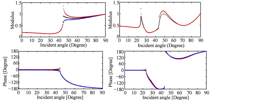
Figure 4. Modulus and phase of the reflection
 versus the incidence angle for:
 and
and
 (dashed red lines),
 and
and
 (dashed blues lines),
 (dashed black lines). Low contrast case (left) and high contrast (right).
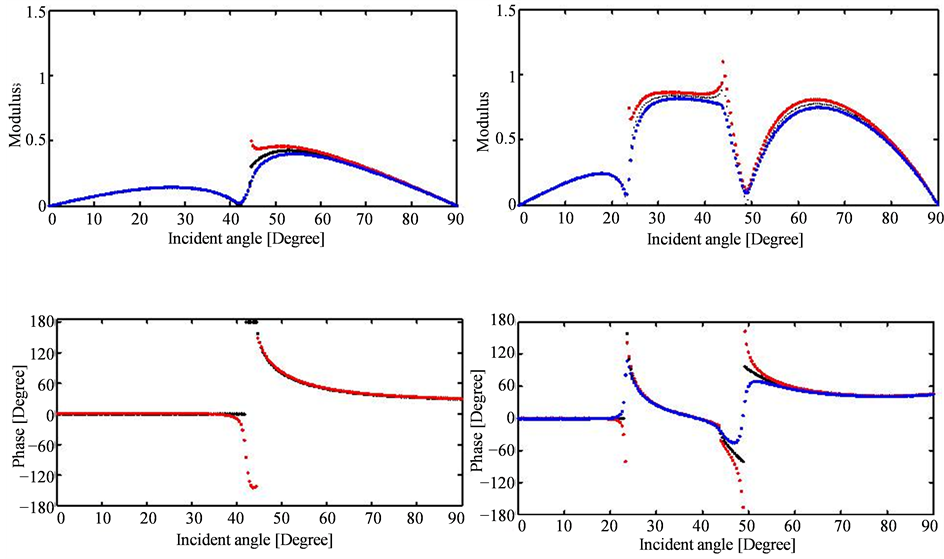
Figure 5. Modulus and phase of the reflection
 versus the incidence angle for:
 and
and
 (dashed red lines),
 and
and
 (dashed blues lines),
 (dashed black lines). Low contrast case (left) and high contrast (right).
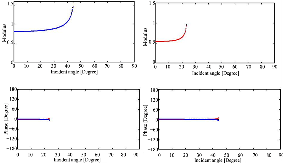
Figure 6. Modulus and phase of the transmission
 versus the incidence angle for:
 and
and
 (dashed red lines),
 and
and
 (dashed blue lines),
 (dashed black lines). Low contrast case (left) and high contrast (right).
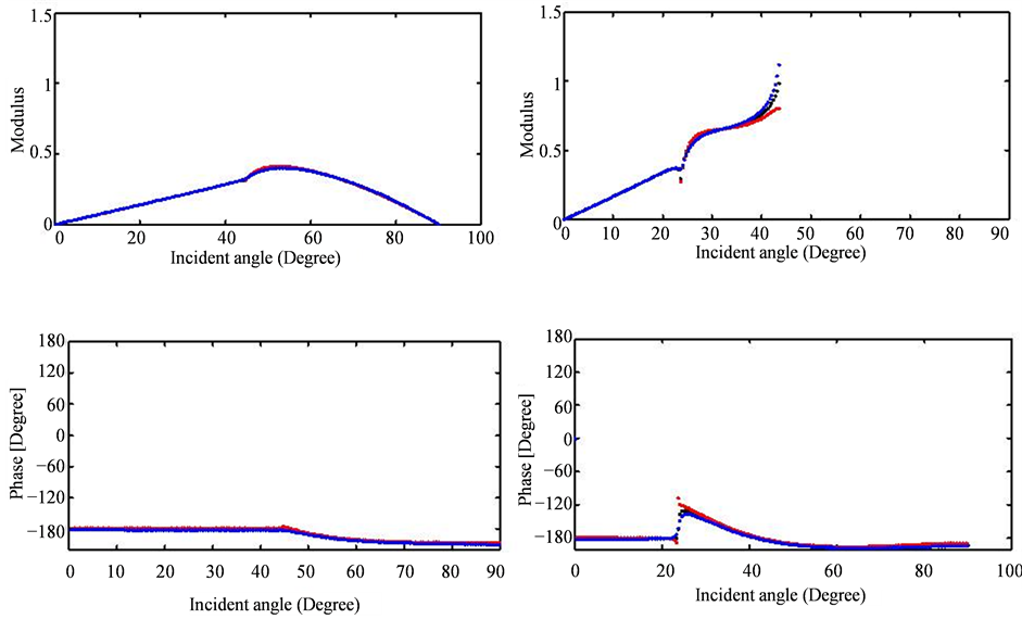
Figure 7. Modulus and phase of the transmission
 versus the incidence angle for:
 and
and
 (dashed red lines),
 and
and
 (dashed blue lines),
 (dashed black lines). Low contrast case (left) and high contrast (right).
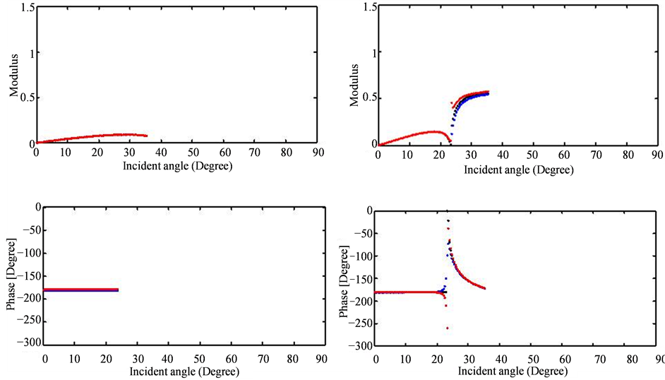
Figure 8. Modulus and phase of the transmission
 versus the incidence angle for:
 and
and
 (dashed red lines),
 and
and
 (dashed blue lines),
 (dashed black lines). Low contrast case (left) and high contrast (right).
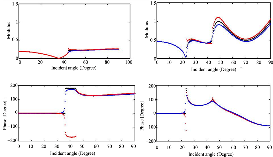
Figure 9. Modulus and phase of the transmission
 versus the incidence angle for:
 and
and
 (dashed red lines),
 and
and
 (dashed blue lines),
 (dashed black lines). Low contrast case (left) and high contrast (right).
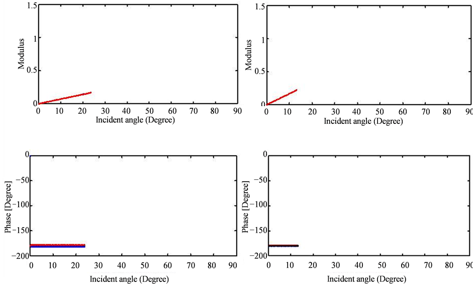
Figure 10. Modulus and phase of the transmission
 versus the incidence angle for:
 and
and
 (dashed red lines),
 and
and
 (dashed blue lines),
 (dashed black lines). Low contrast case (left) and high contrast (right).
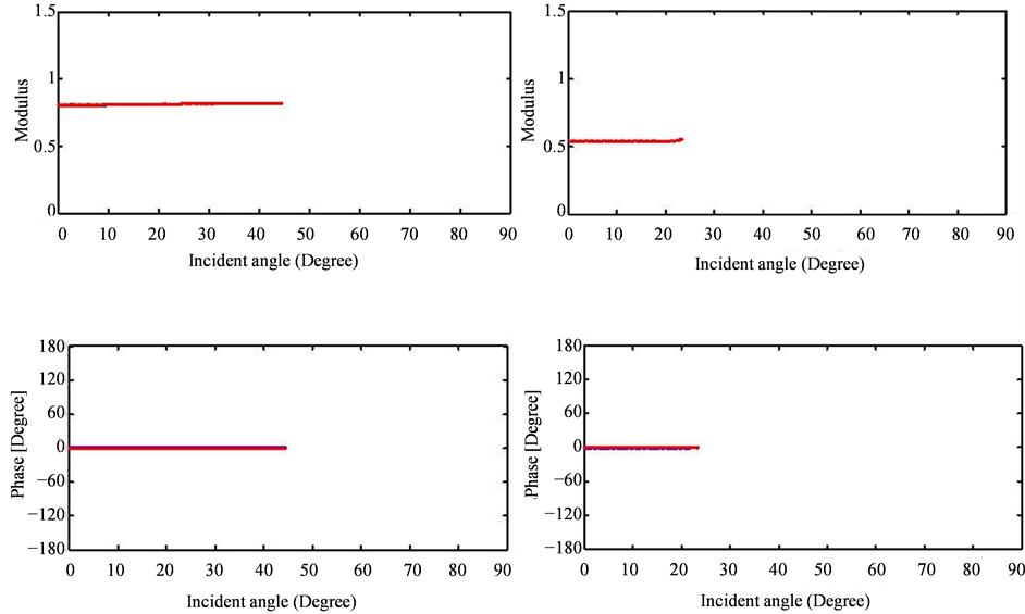
Figure 11. Modulus and phase of the transmission
 versus the incidence angle for:
 and
and
 (dashed red lines),
 and
and
 (dashed blue lines),
 (dashed black lines). Low contrast case (left) and high contrast (right).
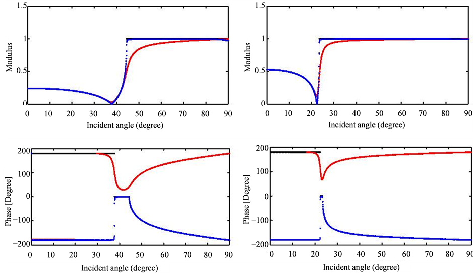
Figure 12. Modulus and phase of the transmission
 versus the incidence angle for:
 and
and
 (dashed red lines),
 and
and
 (dashed blue lines),
 (dashed black lines). Low contrast case (left) and high contrast (right).
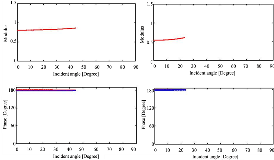
Figure 13. Modulus and phase of the transmission
 versus the incidence angle for:
 and
and
 (dashed red lines),
 and
and
 (dashed blue lines),
 (dashed black lines). Low contrast case (left) and high contrast (right).
in the figures and the viscoelastic coefficients indicated by the blue and red colors can be significant. As we can note in the first case, where the modulus viscoelastic reflection coefficient around the critical angle reach 1.4, bigger than 1 because of the changing in the phase also, while in the elastic case the modulus is equal to 0.9.
The Figures 4-13 show also that when the number of the critical angles is high, as in the case 2, the
 coefficients are more affected by the viscoelasticity of the medium.
9. Conclusions
The above results show that in the viscoelastic media,
 coefficients between two neighboring layers depend on the contrast of their quality factor. The effect of the contrast is effective around the critical angles, which depends on the incidence angle and the velocities of each layer. The number of the critical angles increases when the velocity contrast is large and in this case the
 coefficients are more disturbed by the viscoelasticity of the medium. We noted that when the upper layer has bigger attenuation than the lower layer
 , the curves display a discontinuity at the critical angle.
The interpretation of the above observations is difficult to interpret and we do not know if it has a physical meaning or just a mathematical artefact. More understanding of the reflection/transmission mechanism in the viscoelastic media is necessary to interpret these results.
References
- Aki, K. and Richards, P. (1980) Quantitative Seismology. Theory and Methods. Freeman, San Francisco.
- Shuey, R.T. (1985) A Simplification of the Zoeppritz Equations. Geophysics, 50, 609-614. http://dx.doi.org/10.1190/1.1441936
- Tao, W.P., Dong, S-H. and Yang, L. (2008) Forward Modeling to Improve Seismic Reflection Energy of a Protective Coal Seam Based on Zoeppritz Equation. Geophysics, 18, 46-49.
- Krebes, E.S. (1983) The Viscoelastic Reflection/Transmission Problem: Two Special Cases. Bulletin of the Seismological Society of America, 73, 1673-1683.
- Buchen, P.W. (1971) Reflection and Diffraction of SH-Waves in Linear Viscoelastic Solids. Geophysics, 25, 97-113.
- Carcione, J.M. and Tinevella, U. (2000) Bottom-Simulating Reflectors: Seismic Velocities and AVO Effects. Geophysics, 65, 54-67. http://dx.doi.org/10.1190/1.1444725
- Bouchaala, F. (2008) Modelisation de la propagation des ondes sismiques dans les milieuviscoelastiques: Application a la determination de l’attenuation des milieux sedimentaires. Ph.D. Dissertation, University of Western Brittany, Brest.
- Cerveny, V. (2001) Seismic Ray Theory. Cambridge University Press, Cambridge. http://dx.doi.org/10.1017/CBO9780511529399
- Lavergne, M. (1986) Methodes Sismiques. Technip, Paris.
Appendix

Expression of the reflection-transmission coefficients (P-SV) in isotropic, inhomogeneous and viscoelastic medium

with:


and
![]()
![]()
![]()

After doing the below substitution in the above expressions of reflection-transmission coefficients,

 for
for
![]()

and
 for P incident wave and
 for S incident wave we obtain:


And also,

Now we compute
 and
and


With


Table A1. Component in the basis
 of stress vector at
 due to incident, reflected, and transmitted waves (Reflection/Transmission P-SV).