Journal of Flow Control, Measurement & Visualization
Vol.03 No.01(2015), Article ID:53255,12 pages
10.4236/jfcmv.2015.31003
Plasma Virtual Actuators for Flow Control
Kwing-So Choi1*, Timothy N. Jukes2, Richard D. Whalley3, Lihao Feng4, Jinjun Wang4, Takayuki Matsunuma5, Takehiko Segawa5
1Faculty of Engineering, University of Nottingham, Nottingham, UK
2Dyson Technology Ltd., Malmesbury, UK
3School of Engineering, University of Liverpool, Liverpool, UK
4Fluid Mechanics Key Laboratory of Education Ministry, Beihang University, Beijing, China
5Energy Technology Research Institute, AIST, Tsukuba, Japan
Email: *kwing-so.choi@nottingham.ac.uk
Copyright © 2015 by authors and Scientific Research Publishing Inc.
This work is licensed under the Creative Commons Attribution International License (CC BY).
http://creativecommons.org/licenses/by/4.0/


Received 30 October 2014; accepted 23 December 2014; published 15 January 2015
ABSTRACT
Dielectric-barrier-discharge (DBD) plasma actuators are all-electric devices with no moving parts. They are made of a simple construction, consisting only of a pair of electrodes sandwiching a dielectric sheet. When AC voltage is applied, air surrounding the upper electrode is ionized, which is attracted towards the charged dielectric surface to form a wall jet. Control of flow over land and air vehicles as well as rotational machinery can be carried out using this jet flow on demand. Here we review recent developments in plasma virtual actuators for flow control that can replace conventional actuators for better aerodynamic performance.
Keywords:
Flow Control, DBD Plasma, Actuators, Aerodynamics, Drag Reduction, Turbulence

1. Introduction
Dielectric-barrier-discharge (DBD) plasma actuators are unique devices that are useful for flow control applications. They are all-electric devices with a simple construction, consisting only of a pair of electrodes sandwiching a dielectric sheet. When AC voltage is applied, air surrounding the upper electrode is ionized, which is attracted towards the charged dielectric surface to form a wall jet [1] - [3] . Figure 1 shows a typical configuration of an asymmetric DBD plasma actuator, showing the region of the plasma and the direction of induced flow (to the right in this figure). The flow velocity could reach to 10 m/s. The induced flow will develop into a wall jet during a continuous operation of plasma actuators, as shown in Figure 2 [4] . Strong entrainment towards the

Figure 1. A typical configuration of DBD plasma actuator [4] .
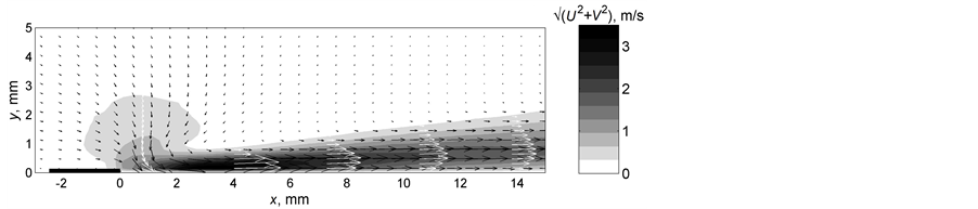
Figure 2. Development of wall jet from a DBD plasma actuator [4] .
wall is clearly seen around the actuator, while the wall-jet velocity profile becomes similar to that created from a two-dimensional nozzle.
Unlike conventional actuators, such as pneumatic, hydraulic and electromagnetic actuators, DBD plasma actuators do not require any moving parts, such as valves, diaphragms, cylinders or gears, in order to activate them. For example, it is possible to replace conventional “mechanical” vortex generators with DBD plasma actuators, called plasma vortex generators (VGs). Here, the profile drag penalty that is associated with mechanical vortex generators can be avoided by activating DBD plasma actuators on demand when and as required. DBD plasma actuators can be used to actively control the flow around vehicles, easily adapting to their operating conditions. They are much faster acting than any actuators currently available, which can be integrated well with hybrid and electric motor vehicles as well as future all-electric aircraft.
In this review paper, we introduce a number of examples where plasma actuators can be used for flow control purposes in place of conventional actuators. Our examples include plasma vortex generators, plasma Gurney flaps, plasma travelling wave makers and plasma tip-clearance seals, although there are many more potential plasma virtual actuators.
2. Plasma Vortex Generators
By tailoring the direction of the wall jet from a DBD plasma actuator it is possible to create strong longitudinal vortices, similar to those created by vane-type vortex generators (VGs). A typical DBD plasma VG is configured with a single plasma actuator aligned along the primary air flow direction. The electro-hydrodynamic body force and resulting wall jet are directed into the spanwise direction, perpendicular to the incoming flow. The wall jet consequently becomes twisted into the streamwise direction by the oncoming boundary layer [4] . This forms a streamwise vortex from the plasma actuator tip by the twisting and folding of spanwise vorticity in the boundary layer into the outer shear layer of the wall jet, as drawn schematically in Figure 3. The wall jet then continually adds vorticity to increase the circulation along the length of the actuator. In addition to creating longitudinal vortices like conventional VGs, there is extra wall-ward suction due to entrainment into the DBD plasma [4] . Of course the DBD plasma VGs can be rapidly switched on and off as required without adding profile drag because it is a flush mounted device.
DBD plasma VGs have been studied singly [4] [5] , where it was found that the streamwise vortex circulation increases with wall jet-to-freestream velocity ratio. The circulation also increases with the actuator length and is maximized when the actuator is placed parallel to the freestream direction (i.e. with no yaw angle). Thus stronger vortices are created by long, stream wise-oriented DBD plasma VGs at high voltage and/or frequency. For practical use, however, DBD plasma VGs can be easily configured into VG arrays [5] [6] . Different types of array may be produced by simply changing the configuration of the lower electrode (see Figure 4). Streamwise vortices created from two different types of VG arrays are shown for example in Figure 5. DBD plasma VGs

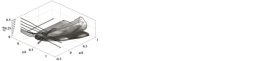
Figure 3. Streamwise vortex formation mechanism (left) and vorticity iso-surface Ωxδ/U∞ = ±3.5 at VG tip (right) [4] .
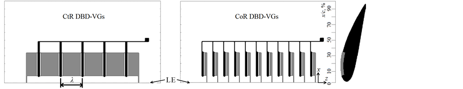
Figure 4. Counter-rotating (left) and co-rotating (right) DBD plasma VG arrays on an airfoil [6] . 125 micron Polyimide actuator sheets bonded onto NACA 4418 airfoil of 100 mm chord and 200 mm span. Exposed plasma electrodes (black) are 2.5 mm wide and 35 micron thick. Plasma formation with 4.8 & 6.0 kV p-p sinusoidal ac voltage at 7 kHz.
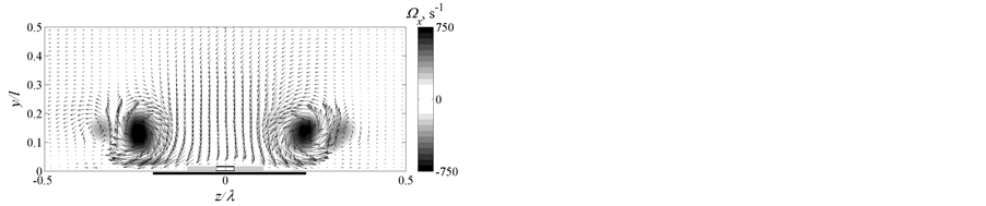
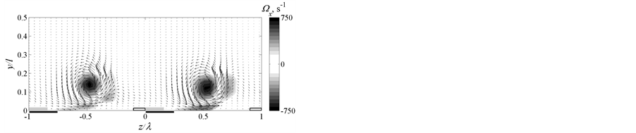
Figure 5. Velocity and vorticity distribution of streamwise vortices created by counter-rotating (left) and co- rotating (right) DBD plasma VGs arrays [5] .
with continuous lower electrodes produce wall jets on both sides of the upper electrodes, thus forming pairs of counter-rotating vortices with common-flow towards the wall. DBD plasma VGs with staggered lower electrodes produce wall jets only on one side of each upper electrode, forming arrays of co-rotating vortices. Generally counter-rotating DBD plasma VGs are more effective for flow separation control due to larger wall-ward velocity component, but care should be taken to choose the correct spacing to prevent unfavorable interactions between adjacent vortices whilst maintaining sufficient coverage for effective flow control [5] [6] .
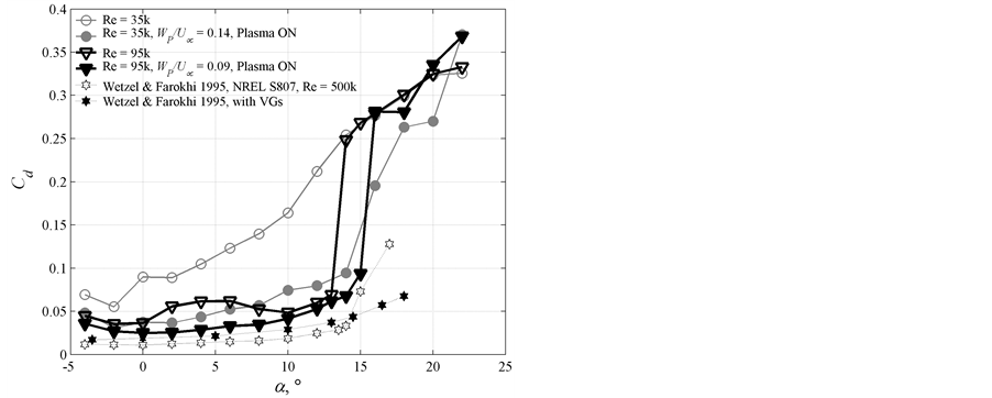
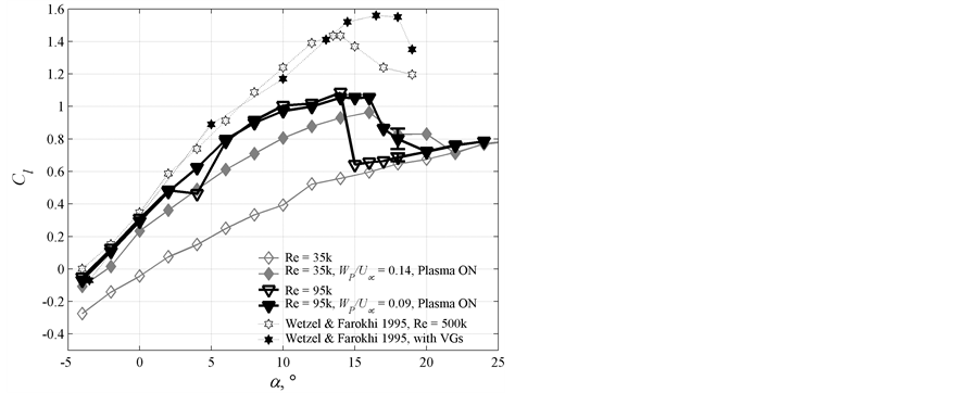
The DBD plasma VG arrays have been applied near the leading edge of a NACA 4418 airfoil for flow separation control [6] . These mitigated separation at wall jet-to-freestream velocity ratio Wp/U∞ = 14% for all angles of attack less than 22˚ at Rec = 3.5 × 10⁴. This resulted in up to 65% reduction in drag coefficient and an increase in lift coefficient by ΔCl = 0.4, as shown in Figure 6. These actuators were also effective at Rec = 9.5 × 10⁴, where a separation bubble could be eliminated at low angles of attack (2˚ < α < 8˚), and leading-edge stall delayed until α = 16˚. This stall delay is very similar behavior to conventional VGs [7] , except that conventional VGs cause a significant drag increase whereas plasma VGs do not (see Figure 6(a)). A counter-rotating array of DBD plasma VGs was also successfully used on a NACA 0015 airfoil at Rec = 1.6 × 10⁵, as shown in Figure 7. Here, a trailing-edge flow separation was controlled and stall prevented up to α = 14.8˚ [8] . DBD plasma VG arrays have also been used to mitigate stall on a 20˚ backward facing ramp for Wp/U∞ > 7% (U∞ < 15 m/s) [5] .
DBD plasma VGs can be more versatile and effective than plasma actuators aligned across the span, largely because plasma VGs can act over a large streamwise domain. As such there is potential for DBD plasma VGs in rotating stall applications, for example on a wind turbine. Figure 8 shows phase-averaged velocity measurements
 (a) (b)
Figure 6. Drag (a) and lift coefficient enhancement (b) with counter-rotating DBD-VGs on a NACA 4418 airfoil [6] .
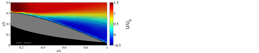
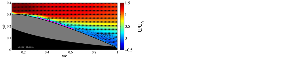
Figure 7. Flow separation control over a NACA 0015 airfoil with CtR DBD plasma VGs. Without actuation (on the left) and with actuation (right) at Rec = 1.6 × 10⁵ at an angle of attack α = 14.2˚ [8] .
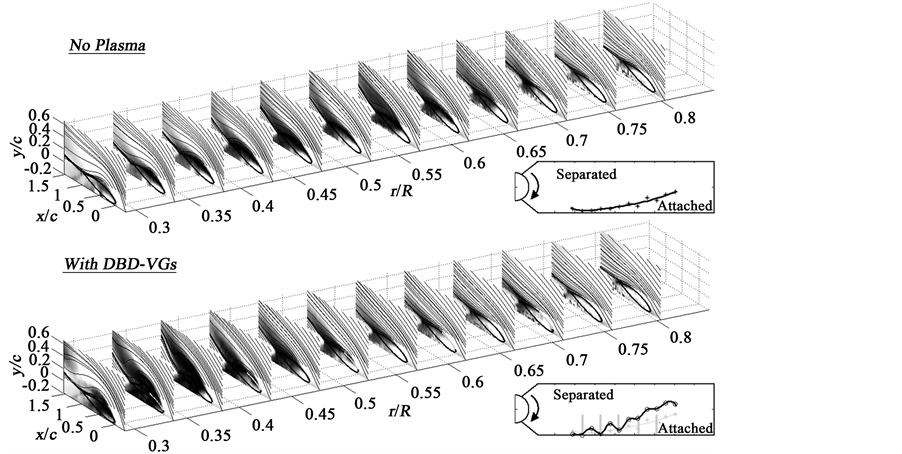
Figure 8. Flow separation control over a rotating wind turbine blade (NREL S822) with DBD plasma VGs. Phase-averaged velocity without (top) and with actuation (bottom) at tip Rec = 40 × 103 and tip-speed-ratio UR/U∞ = 3.7.
at numerous radial stations over a rotating NREL S822 wind turbine blade. Identical counter-rotating DBD plasma VGs were used as on the left of in Figure 4 over radial location 0.34 < r/R < 0.71, where R is the blade tip radius. Without plasma, a zone of flow separation spreads from the inboard of the blade as the tip-speed-ratio reduces. With plasma, rotating stall was delayed which causes a shift in the flow separation zone back towards the hub. This can be clearly seen in Figure 8, where the dark stalled region (low velocity) moves from around 0.35 < r/R < 0.7 to 0.3 < r/R < 0.5 when DBD plasma VGs are turned on. Since it is the outer part of the blade that generates the majority of the power, this should have a significant improvement on the turbine power output in unfavorable wind conditions such as during start-up and with wind shear. The plasma can also respond very quickly to enhance power generation in gusty wind conditions, potentially through feedback control [9] .
3. Plasma Gurney Flaps
Gurney flaps consist of a small vertical plate of a few percent chord attached over the pressure side of an airfoil at the trailing edge. Despite its size and simplicity of its design, the lift coefficient can be greatly increased by Gurney flaps with only a small increase in drag coefficient [10] . The lift enhancement by Gurney flaps comes from two sources. The first is a low-speed separation bubble formed in front of the flap, creating a high pressure region. This increases the pressure difference across the airfoil to help increase the lift coefficient. The second is a recirculation region formed in the downstream of the flap, which acts to increase the airfoil camber to help attach the separating flow near the trailing edge.
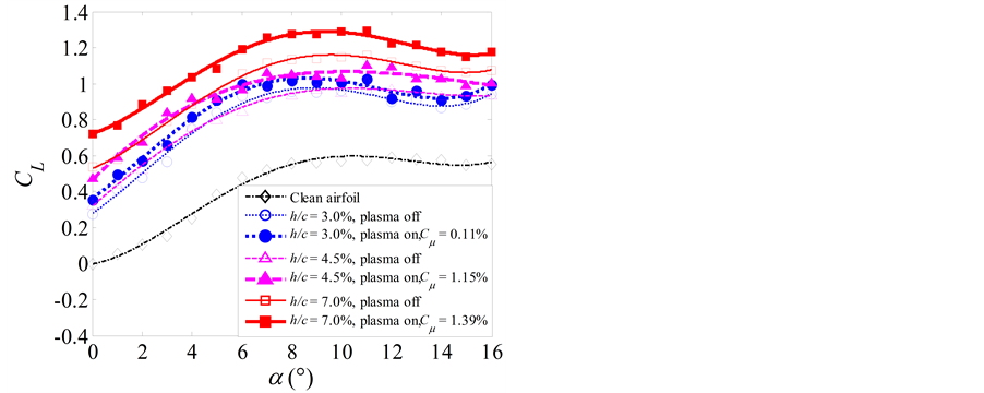
Zhang et al. set a plasma actuator on the blunt trailing edge of a NACA 0012 airfoil [11] , demonstrating that the plasma control could increase the lift coefficient in a similar way as a mechanical Gurney flap. Here, the Kutta condition at the airfoil trailing-edge was altered by the plasma-induced wall jet to give an observed lift enhancement [12] . Feng et al. [13] placed a plasma actuator on the downstream surface of a mechanical Gurney flap as shown in Figure 9(a). Three different Gurney flaps with different height h/c = 3.0%, 4.5% and 7.0% were tested with the momentum coefficient of plasma jet Cμ = 0.11%, 1.15%, and 1.39%, respectively. The result is given in Figure 9(b), showing that the lift coefficient of the airfoil is increased with an increase in the Gurney flap height. When the plasma actuator is activated, a further increase in the lift coefficient was observed for all angles of attack tested. The result also suggests that 1% increase in momentum coefficient Cμ of the plasma forcing corresponds to an effective Gurney flap height increment of 1%.
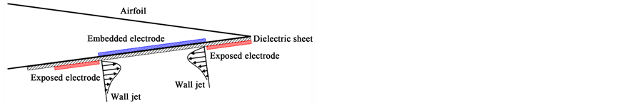
Feng et al. [14] proposed a new concept in designing virtual Gurney flaps by placing DBD plasma actuators onto the bottom surface of the airfoil near the trailing edge. The first configuration of the virtual Gurney flap consisted of two
 (a) (b)
Figure 9. Sketch of the NACA 0012 airfoil with the Gurney flap and plasma actuator proposed by Feng et al. [13] (a) and their effects on the lift coefficient of a NACA 0012 airfoil (b).
 (a) (b)
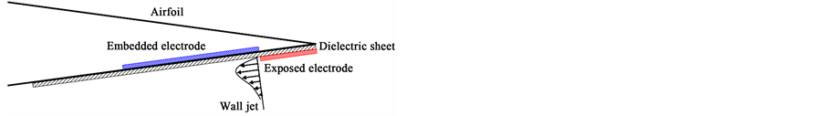
 (c) (d)
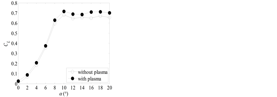
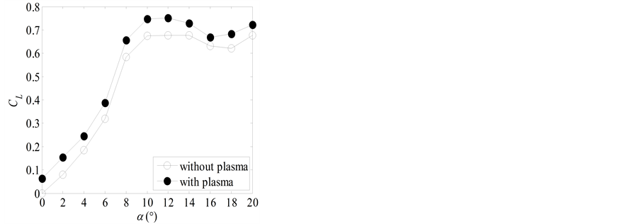
Figure 10. Sketch of configurations 1 (a) and 2 (c) of the plasma Gurney flap proposed by Feng et al. [14] and their effects on the lift coefficient of a NACA 0012 airfoil ((b), (d)).
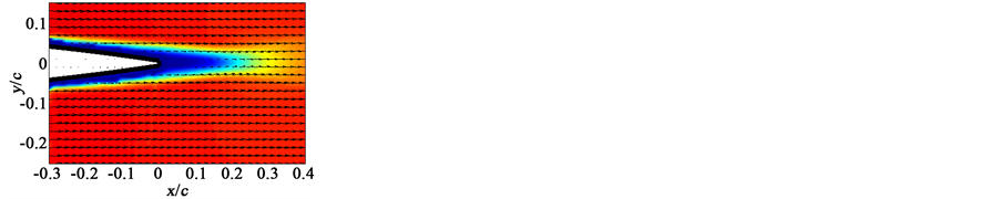
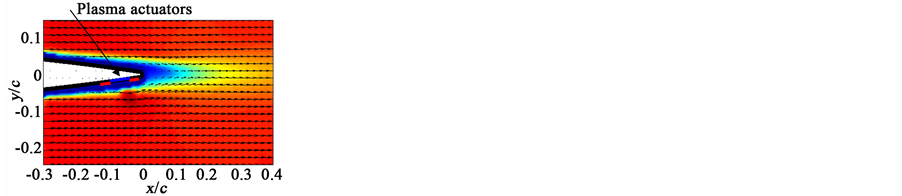
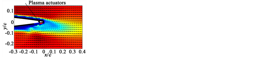
Without plasma, there is a recirculation region downstream of the airfoil trailing edge, which is extended to x/c = 0.12 at the angle of attack α = 0˚ (Figure 11(a)). With plasma control by configuration 1, the size of the recirculation region downstream of the airfoil trailing edge is reduced with the downstream edge located at x/c = 0.04 (Figure 11(b)). There is a high-speed region near the plasma actuators, which is formed by the interaction between the plasma-induced jet and the free stream. On the other hand, there is no difference in the flow field by plasma over the upper surface of the airfoil. When the plasma actuator with configuration 2 is applied, the interaction between the plasma-induced jet and the free stream results in a formation of a recirculation region near the plasma actuator over the pressure surface (Figure 11(c)). This recirculation region draws air from the suction side of the airfoil to increase the velocity, increasing suction on the upper surface. At the same time, a stagnation region with higher pressure is created in the upstream of the recirculation region. Further, the wake region downstream of the airfoil is decreased in size and is shifted downwards (in negative y direction), suggesting that the plasma control increases the equivalent camber of the airfoil. Therefore, the mechanism of the lift enhancement by the virtual Gurney flap is very similar to that of a mechanical Gurney flap but with no profile drag associated with it, just like for DBD plasma VGs.
4. Plasma Travelling Wave Makers
Skin-friction drag reduction by transverse wall motions have been studied extensively in recent years: see Karniadakis and Choi [15] for a review. One particular type of transverse wall motion is achieved by using the spanwise travelling-wave technique, which was first studied by Du and Karniadakis [16] using a direct numerical simulation (DNS). They implemented the spanwise travelling waves at the wall of a turbulent channel flow using a Lorentz force with the following form,
 (a) (b)
 (c)
(c)
Figure 11. Time-averaged velocity superposed with velocity vector for the natural case (a) and plasma control cases with configurations 1 (b) and 2 (c) shown in Figure 10 at α = 0˚ [14] .
 (1)
(1)
Here, Fz is the spanwise force, I is the forcing amplitude, ∆ is the penetration depth, λz = 2π/kz is the spanwise wavelength (kz is the spanwise wave number), T = 2π/ω is the period of forcing (ω is the angular frequency) and t is time. The coordinate system x, y and z are in the streamwise, wall-normal and spanwise direction, respectively. Du et al. [17] demonstrated that the spanwise travelling-wave technique can yield a drag reduction of up to 30% once I, ∆, λz and ω were optimized. The spanwise travelling waves had a profound effect on the near- wall turbulence: they amalgamated the sublayer streaks into wide ribbons of low-speed fluid, which caused significant disruption to the turbulence regeneration cycle. Experimental investigations of spanwise travelling waves with electromagnetic actuation soon followed [18] [19] , where Xu and Choi [19] observed the formation of the wide ribbons of low-speed fluid within the viscous sublayer and measured a 30% reduction in skin-fric- tion drag.
Spanwise travelling waves were also implemented with out-of-plane motions of a flexible wall. In their DNS, Zhao et al. [20] observed a skin-friction drag reduction of 30% due to the change in boundary-vorticity flux that was generated by the acceleration of the deforming wall. Itoh et al. [21] and Itoh and Tamano [22] studied experimentally the out-of-plane motion of a flexible wall in a turbulent boundary layer. They observed a skin-friction drag reduction of the order of 10%, which was attributed to the reduction in sweep intensity and the increase in the contribution of Reynolds stress by inward-wall interactions. Until recently, spanwise travelling waves have only been created by either a Lorentz force or by a deformable wall. Yet these approaches have drawbacks: Lorentz force actuation works only in a liquid flow, while deformable walls have difficulties in practical implementation. For these reasons, Whalley and Choi [23] conducted an experimental investigation into the use of a plasma travelling wave in air in order to make this innovative flow control technique more applicable to the aerospace sector.
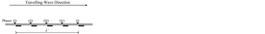
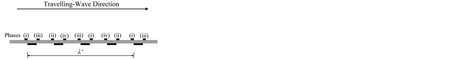
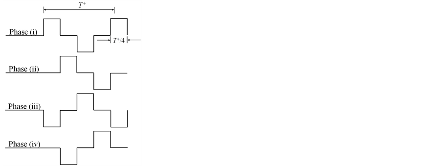
The boundary-layer measurements of Whalley and Choi [23] were performed at a free-stream velocity of U∞ = 1.8 m/s, in a boundary layer with thickness of δ = 90 mm, giving the Reynolds number of Reτ = δuτ/ν = 435, where uτ is the friction velocity and ν is the kinematic viscosity. The plasma travelling waves were generated over a four-phase forcing cycle with either a unidirectional or bidirectional forcing configuration: see Figure 12(a) and Figure 12(b), respectively. For each forcing configuration, the plasma actuators were operated in sequence from phase (i) through to phase (iv) for a duration of T+ (=Tuτ2/ν) each: see Figure 12(c) and Figure 12(d). The unidirectional and bidirectional plasma travelling waves operated either by a single plasma actuator in a spanwise direction, or two plasma actuators in opposing spanwise directions during each phase of forcing,
 (a) (b)
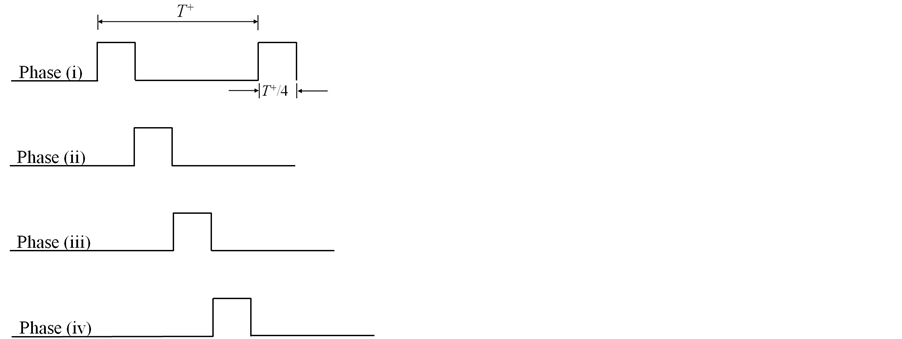
 (c) (d)
Figure 12. Schematic of plasma travelling-wave excitation for (a) unidirectional plasma travelling waves and (b) bidirectional plasma travelling waves; (c) plasma forcing with unidirectional plasma travelling waves and (d) plasma forcing with bidirectional plasma travelling waves. λ+ = 500 (100 mm) and T+ = 82 (208 ms) [23] .
respectively. Both plasma travelling wave configurations implemented the travelling waves over a spanwise wavelength of λ+ = λuτ/ν = 500 in a period of T+ = 82.
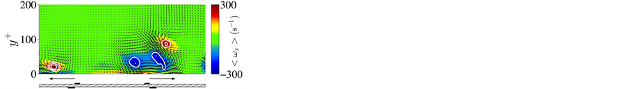
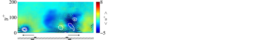
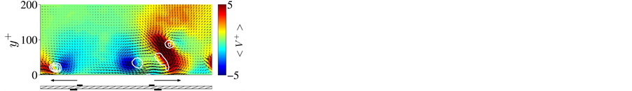
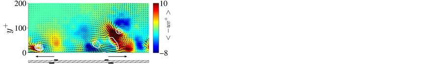
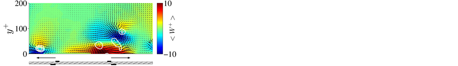
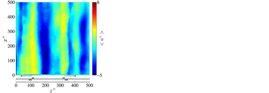
Changes to the structure of the turbulent boundary layer with plasma travelling waves are shown in Figure 13. These data have been obtained with 2D PIV in the x-z plane and stereoscopic PIV in the y-z plane and have been phase-averaged over 51 forcing periods. The locations of the plasma actuators are indicated under each image. The plasma travelling waves created streamwise vortices in sequence, which amalgamated the longitudinal vortices within the turbulent boundary layer: see Figure 13(a) and Figure 13(g), which show the streamwise vorticity (ωx) throughout the turbulent boundary layer with the locations of the streamwise vortical flow structures identified by the white contours of the λ2 technique [24] . The positive and negative streamwise vortices generated by the bidirectional plasma travelling waves were a consequence of two plasma actuators operating in opposing spanwise directions during each phase of forcing. The streamwise vortices generated during the plasma travelling-wave control entrained low-speed streamwise velocity (u+) from the near-wall region into their cores and around their peripheries, Figure 13(b) and Figure 13(h), whilst simultaneously creating upwash (V+) and downwash (V+) by vortex induction, Figure 13(c) and Figure 13(i), and thus the production of Reynolds shear stress (−uv+) throughout the boundary layer, Figure 13(d) and Figure 13(j). The plasma actuators generated spanwise velocities (W+) along the wall of the boundary layer, Figure 13(e) and Figure 13(k), which extended to a wall-normal distance of y+ = 50, the location of the cores of the plasma-induced streamwise vortices. Above the location of the vortex cores, the spanwise velocities were created by vortex induction. The regions of downwash coincided with the locations of the plasma actuators and the regions of high-speed streamwise velocity in the near-wall region: see Figure 13(f) and Figure 13(l). Moreover, the formations of wide ribbons of low streamwise velocity were seen upstream of the streamwise vortices which were travelling in the positive spanwise direction.
The amalgamation of the sublayer streaks into wide ribbons of low-speed fluid is a prominent and recurring observation of spanwise travelling-wave control whether implemented with a Lorentz or plasma forcing. Therefore, the formations of the wide ribbons of low streamwise velocity within the viscous sublayer are thought to play an important role in the drag reduction mechanism [16] [17] [23] . Whalley and Choi [23] were able to show using the quadrant analysis that it is the second quadrant (Q-II) and the third quadrant (Q-III) turbulence events

 (a) (g)
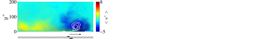
 (b) (h)
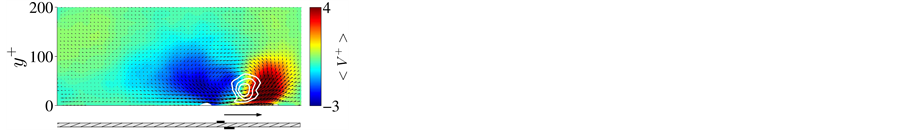
 (c) (i)
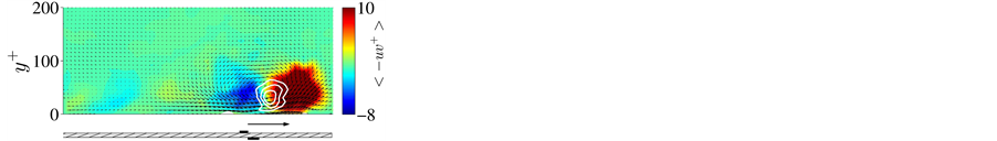
 (d) (j)
 (e) (k)
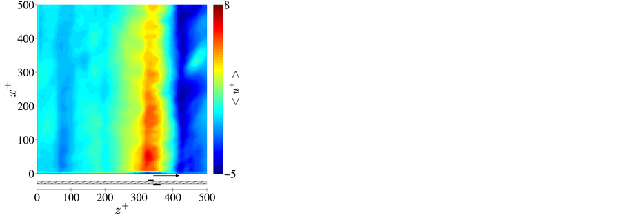
 (f) (l)
Figure 13. A comparison of data in the y-z plane and x-z plane of the turbulent boundary layer with unidirectional plasma travelling waves ((a)-(f)) and bidirectional plasma travelling waves ((g)-(l)) at 3/4T+ showing ((a), (g)) streamwise vorticity (ωx; y-z plane); ((b), (h)) fluctuating streamwise velocity (u+; y-z plane); ((c), (i)) wall-normal velocity (V+; y-z plane); ((d), (j)) Reynolds shear stress (−uv+; y-z plane); ((e), (k)) spanwise velocity (W+; y-z plane); ((f), (l)) fluctuating streamwise velocity (u+; x-z plane). All results are scaled with canonical uτ. The white contours of negative λ2 illustrate the locations of vortical flow structures [24] .
created by the plasma-induced streamwise vortices that are directly responsible for the formation of the wide- ribbons of low-speed fluid within the viscous sublayer with plasma travelling-wave control.
5. Plasma Tip-Clearance Seals
Since Roth et al. [25] demonstrated their potential, conventional two-dimensional, sheet-type DBD plasma actuators (see Figure 1) were used in a number of flow control applications. However, there are many technical problems in attaching DBD plasma actuators on three-dimensional metallic (electrically conducting) surfaces. One of the solutions is to use new string-type DBD plasma actuators (Patent WO2014/024590 pending) being developed at AIST [26] [27] . Figure 14 shows a schematic view of a string-type DBD plasma actuator, consisting of a flexible metallic wire coated with an insulating (dielectric) material, instead of an encapsulated, sheet electrode. When string-type DBD plasma actuators are attached to a metallic surface, the exposed electrode is unnecessary because the metallic (electrically conductive) surface can be used as an exposed electrode for plasma discharge. If elastic materials such as polytetrafluoroethylene (PTFE) or silicone resin are chosen for the wire insulation material for string-type DBD plasma actuators, it is also possible to attach these actuators over three-dimensional surfaces. String-type DBD plasma actuators also offer an advantage over conventional sheet- type DBD plasma actuators that damaged actuators can be easily replaced.
With regard to tip clearance flow control of turbines, Van Ness et al. [28] investigated the effect of active control using blade-tip-mounted plasma actuators. Saddoughi et al. [29] also investigated the tip clearance flow control using plasma actuators upstream of the rotor leading edge of a transonic compressor. Here, tip clearance loss of a turbine blade can account for as much as 40% of the total energy loss [30] , therefore, this topic has been intensively studied over the years. For a comprehensive review of tip clearance flow and its effects on the performance of turbo-machineries, readers are referred to Sjolander [31] .
String-type DBD plasma actuators can be used to mitigate of tip clearance flow in turbo-machineries such as gas turbines and turbochargers, by simply applying high voltages at radio frequencies. Our strategy in using string-type DBD plasma actuators is quite simple, which is illustrated in Figure 15. Here, the turbine blades, casing wall, and other surface conductive materials are connected to ground for safety. On the other hand, metal wires, for which high voltages are applied, are covered by insulating materials and embedded in the casing wall. DBD plasma is formed selectively in the regions where the turbine blade tips come close to the casing wall during the rotation of turbine blades.
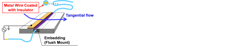
Figure 14. String-type DBD plasma actuator.
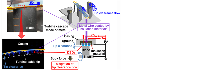
Figure 15. Ring-type DBD plasma actuators applied to a gas turbine casing to mitigate tip clearance.
Figure 16 shows the flow field of hot-wire measurements [32] . The axial distance of the measurement plane is 10.3 mm from the rotor trailing edge. This is 60% of the axial chord length of the turbine blade at the tip (Cax,tip) downstream (in z-direction) from the trailing edge, i.e. z/Cax,tip = 1.60. Figure 17 shows the turbulence intensity distributions at the rotor exit for various input voltages. Here, the turbulence intensity was normalized by the main flow velocity at the rotor exit. At the baseline condition (Figure 17(a)), a high turbulence intensity region exists near the tip endwall, due to the tip leakage flow (tip leakage vortex). No significant change was observed at the lower input voltages (Figure 17(b) and Figure 17(c)) when the plasma is applied to string-type actuators; however, at the higher input voltages (Figure 17(d) and Figure 17(e)), the high turbulence intensity region is gradually reduced. The peak of turbulence intensity, at VAC = ±6.0 kV, is 0.18, which represents a 22% reduction compared to the peak at the baseline (0.23). The reduction in turbulence intensity confirms the successful reduction of tip leakage flow by this type of plasma actuator.
6. Conclusion
DBD plasma actuators have been demonstrated as virtual vortex generators, virtual Gurney flaps, travelling wave makers and tip-clearance seals, where significant improvements in aerodynamic and flow control performance could be made. As such, DBD plasma actuators offer advantages over conventional actuators in such applications. The main issue for an industrial application of DBD plasma actuators is their authority at higher speeds. This requires further development of the power supply as well as actuator materials and construction, which are, however, feasible with the existing technology. The design of these plasma virtual actuators does not require as high jet velocity as some of other actuator concepts; therefore, they are readily available for application to automobiles and UAVs (unmanned aerial vehicles).
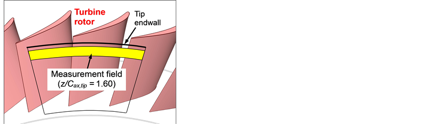
Figure 16. Hot-wire measurement region at the turbine rotor exit [32] .
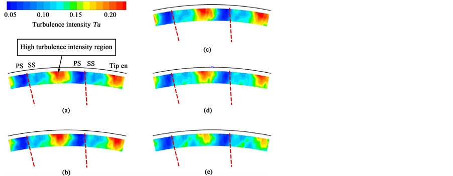
Figure 17. Turbulence intensity profile at the turbine rotor exit with various input voltages [32] . PS and SS indicate the pressure side and suction side of the turbine blade, respectively. (a) Baseline; (b) Flow control (VAC = ±3.0 kV); (c) Flow control (VAC = ±4.0 kV); (d) Flow control (VAC = ±5.0 kV); (e) Flow control (VAC = ±6.0 kV).
Acknowledgements
Gratitude is due to EPSRC Research Grant EP/G025150/1, the China Scholarship Council and the Royal Academy of Engineering for supporting this research programme. T.J. would like to acknowledge funding from the University of Nottingham Advance Research Fellowship (NARF), while L.F. would like to thank the support of Specialized Research Fund for the Doctoral Program of Higher Education (20121102120015) and the Fundamental Research Funds for the Central Universities (YWF-14-HKXY-007). R.D.W. acknowledges the support in part of the EPSRC PhD plus Fellowship to carry out this work.
References
- Moreau, E. (2007) Airflow Control by Non-Thermal Plasma Actuators. Journal of Physics D: Applied Physics, 40, 605-636. http://dx.doi.org/10.1088/0022-3727/40/3/S01
- Corke, T.C., Enloe, C.L. and Wilkinson, S.P. (2010) Dielectric Barrier Discharge Plasma Actuators for Flow Control. Annual Review of Fluid Mechanics, 42, 505-529. http://dx.doi.org/10.1146/annurev-fluid-121108-145550
- Wang, J.J., Choi, K.-S., Feng, L.-H., Jukes, T.N. and Whalley, R.D. (2013) Recent Developments in DBD Plasma Flow Control. Progress in Aerospace Sciences, 62, 52-78. http://dx.doi.org/10.1016/j.paerosci.2013.05.003
- Jukes, T. and Choi, K.-S. (2013) On the Formation of Streamwise Vortices by Plasma Vortex Generators. Journal of Fluid Mechanics, 733, 370-393. http://dx.doi.org/10.1017/jfm.2013.418
- Jukes, T. and Choi, K.-S. (2012) Dielectric-Barrier-Discharge Vortex Generators: Characterization and Optimization for Flow Separation Control. Experiments in Fluids, 52, 329-345. http://dx.doi.org/10.1007/s00348-011-1213-0
- Jukes, T., Segawa, T. and Furutani, H. (2013) Flow Control on a NACA 4418 Using Dielectric-Barrier-Discharge Vortex Generators. AIAA Journal, 51, 452-464. http://dx.doi.org/10.2514/1.J051852
- Wetzel, K.K. and Farokhi, S. (1995) Influence of Vortex Generators on NREL S807 Airfoil Aerodynamic Characteristics and Wind Turbine Performance. Wind Engineering, 19, 157-165.
- Whalley, R.D., Debien, A., Podlinski, J., Jukes, T.N., Choi, K.-S., Benard, N., Moreau, E., Berendt, A. and Mizeraczyk, J. (2013) Trailing-Edge Separation Control of a NACA 0015 Airfoil Using Dielectric-Barrier-Discharge Plasma Actuators. ERCOFTAC Bulletin, 94, 35-40.
- Jukes, T., Segawa, T. and Furutani, H. (2012) Active Flow Separation Control on a NACA 4418 Using DBD Vortex Generators and FBG Sensors. 50th AIAA Aerospace Sciences Meeting including the New Horizons Forum and Aerospace Exposition, AIAA 2012-1139.
- Wang, J.J., Li, Y.C. and Choi, K.-S. (2008) Gurney Flap-Lift Enhancement, Mechanisms and Applications. Progress in Aerospace Sciences, 44, 22-47. http://dx.doi.org/10.1016/j.paerosci.2007.10.001
- Zhang, P.F., Liu, A.B. and Wang, J.J. (2009) Aerodynamic Modification of a NACA 0012 Airfoil by Trailing-Edge Plasma Gurney Flap. AIAA Journal, 47, 2467-2474. http://dx.doi.org/10.2514/1.43379
- Li, Y.C., Wang, J.J. and Zhang, P.F. (2002) Effect of Gurney Flaps on a NACA 0012 Airfoil. Flow, Turbulence Combust, 68, 27-39. http://dx.doi.org/10.1023/A:1015679408150
- Feng, L.H., Jukes, T.N., Choi, K.-S. and Wang, J.J. (2012) Flow Control over a NACA 0012 Airfoil Using Dielectric- Barrier-Discharge Plasma Actuator with a Gurney Flap. Experiments in Fluids, 52, 1533-1546. http://dx.doi.org/10.1007/s00348-012-1263-y
- Feng, L.H., Wang, J.J. and Choi, K.-S. (2014) A Novel Concept on the Plasma Gurney Flap. Proceedings of the 29th Congress of the International Council of the Aeronautical Sciences, St. Petersburg, 7-12 September 2014, 1-7.
- Karniadakis, G.E. and Choi, K.-S. (2003) Mechanisms on Transverse Motions in Turbulent Wall Flows. Annual Review of Fluid Mechanics, 35, 45-62. http://dx.doi.org/10.1146/annurev.fluid.35.101101.161213
- Du, Y. and Karniadakis, G.E. (2000) Suppressing Wall Turbulence by Means of a Transverse Travelling Wave. Sci- ence, 288, 1230-1234. http://dx.doi.org/10.1126/science.288.5469.1230
- Du, Y., Symeondis, Y. and Karniadakis, G.E. (2002) Drag Reduction in Wall-Bounded Turbulence via a Transverse Travelling Wave. Journal of Fluid Mechanics, 457, 1-34. http://dx.doi.org/10.1017/S0022112001007613
- Breuer, K., Park, J. and Henoch, C. (2004) Actuation and Control of a Turbulent Channel Flow Using Lorentz Forces. Physics of Fluids, 16, 897-907. http://dx.doi.org/10.1063/1.1647142
- Xu, P. and Choi, K.-S. (2006) Boundary-Layer Control for Drag Reduction by Lorentz Forcing. Proceedings of the IUTAM Symposium on Flow Control and MEMS, London, 19-22 September 2006.
- Zhao, H., Wu, J.Z. and Luo, J.S. (2004) Turbulent Drag Reduction by Traveling Wave of Flexible Wall. Fluid Dynamics Research, 34, 175-198. http://dx.doi.org/10.1016/j.fluiddyn.2003.11.001
- Itoh, M., Tamano, S., Yokota, K. and Tanigichi, S. (2006) Drag Reduction in a Turbulent Boundary Layer on a Flexible Sheet Undergoing a Spanwise Travelling Wave Motion. Journal of Turbulence, 7, 1-17. http://dx.doi.org/10.1080/14685240600647064
- Itoh, M. and Tamano, S. (2012) Drag Reduction in Turbulent Boundary Layers by Spanwise Travelling Waves with Wall Deformation. Journal of Turbulence, 13, 1-26.
- Whalley, R.D. and Choi, K.-S. (2014) Turbulent Boundary-Layer Control with Plasma Spanwise Travelling Waves. Experiments in Fluids, 55, 1796. http://dx.doi.org/10.1007/s00348-014-1796-3
- Jeong, J. and Hussain, F. (1995) On the Identification of a Vortex. Journal of Fluid Mechanics, 285, 69-94. http://dx.doi.org/10.1017/S0022112095000462
- Roth, J.R., Sherman, D.M. and Wilkinson, S.P. (1998) Boundary Layer Flow Control with a One Atmosphere Uniform Glow Discharge. AIAA Paper 98-0328.
- Segawa, T., Jukes, T. and Yuki, Y. (2012) Properties of Flow Induced by String-Type Plasma Actuators. Nagare, 31, 479-482.
- Segawa, T., Jukes, T., Yuki, Y., Maeda, S., Maeda, T., Ogata, S. and Takekawa, S. (2013) Feedback Control of Flow Separation on NACA 0024 Airfoil under Periodic Wall Oscillation by Means of DBD Plasma Actuator and FBG Sensor. AIAA Paper 2013-1117.
- Van Ness II, D.K., Corke, T.C. and Morris, S.C. (2006) Turbine Tip Clearance Flow Control Using Plasma Actuator. AIAA Paper 2006-0021.
- Saddoughi, S., Bennett, G., Boespflug, M., Puterbaugh, S.L. and Wadia, A.R. (2014) Experimental Investigation of Tip Clearance Flow in a Transonic Compressor with and without Plasma Actuators. Proceedings of the ASME Turbo Expo 2014, GT2014-25294.
- Matsunuma, T. (2006) Effects of Reynolds Number and Freestream Turbulence on Turbine Tip Clearance Flow. Transactions of the American Society of Mechanical Engineers: Journal of Turbomachinery, 128, 166-177.
- Sjolander, S.A. (1997) Overview of Tip-Clearance Effects in Axial Turbines. Von Karman Institute for Fluid Dyna- mics, Lecture Series 1997-01: Secondary and Tip-Clearance Flows in Axial Turbines, 1-29.
- Matsunuma, T. and Segawa, T. (2014) Active Tip Clearance Flow Control for an Axial-Flow Turbine Rotor Using Ring-Type Plasma Actuators. Proceedings of the ASME Turbo Expo 2014, GT2014-26390.
NOTES

*Corresponding author.