Open Journal of Optimization
Vol.2 No.3(2013), Article ID:36839,8 pages DOI:10.4236/ojop.2013.23010
Human-Robot Collaborative Planning for Navigation Based on Optimal Control Theory
Hydrogen Research Institute, Department of Mechanical Engineering, Université du Québec à Trois-Rivières, Trois-Rivières, Canada
Email: Sousso.kelouwani@uqtr.ca
Copyright © 2013 Sousso Kelouwani. This is an open access article distributed under the Creative Commons Attribution License, which permits unrestricted use, distribution, and reproduction in any medium, provided the original work is properly cited.
Received May 17, 2013; revised July 28, 2013; accepted August 9, 2013
Keywords: Robotic Architecture; Share Control; Three-Layer Architecture; Cooperative Control; Collaborative Control; Optimal Control
ABSTRACT
Navigation modules are capable of driving a robotic platform without direct human participation. However, for some specific contexts, it is preferable to give the control to a human driver. The human driver participation in the robotic control process when the navigation module is running raises the share control issue. This work presents a new approach for two agents collaborative planning using the optimal control theory and the three-layer architecture. In particular, the problem of a human and a navigation module collaborative planning for a trajectory following is analyzed. The collaborative plan executed by the platform is a weighted summation of each agent control signal. As a result, the proposed architecture could be set to work in autonomous mode, in human direct control mode or in any aggregation of these two operating modes. A collaborative obstacle avoidance maneuver is used to validate this approach. The proposed collaborative architecture could be used for smart wheelchairs, telerobotics and unmanned vehicle applications.
1. Introduction
The human-machine interaction is gaining interest in the robotic community [1-3]. In particular, for robotic platform control, this interaction leads to a share control problem. The robotic platform share control falls into two main categories. The first category is related to situations where the agents (human or intelligent modules embedded on robotic platforms) compete to find the best control action to use [4]. The second category is related to a collaborative approach to achieve a given goal [5-8].
In the context of the collaborative navigation with obstacle avoidance, the agents are often heterogeneous (i.e. a human and a navigation module). The navigation module has the ability to perform a local obstacle avoidance maneuver without the direct human intervention. The human agent is assumed to be able to perform a perceived obstacle avoidance with an appropriate continuous control modality (a joystick or any proportional control device). So, the agents use different obstacle perception modalities and they behave differently during the perceived obstacles avoidance process. In this paper, we consider the collaborative approach for the share control in order to leverage each agent strength.
There is no agreement about the formal definition of collaborative control. However, according to Hoc [3], two minimal conditions are required in order to have two agents to collaborate:
- each agent works towards goals and can interfere with the other;
- each agent tries to manage the interference to facilitate the common task when it exists.
Hence, the definition of common goals is an important aspect of this approach. In order to meet these requirements, most of the collaborative control architectures try to address these three issues:
- the collaboration goal definition;
- the elaboration of the most appropriate plan to meet the identified goal;
- the execution of the selected plan.
The first issue is a decision making problem. The second issue is related to planning whereas the third one is part of the execution problem. When a human is part of two agent team, most applications focus on the decision problem. For the wheelchair collaborative control applications, the intention of the driver is predicted based on the navigation context given by the on-board sensorybased systems [9-12]. By estimating the wheelchair user intention, an appropriate navigation mode is selected. However, the planning (sequence of actions that may be used) is considered as the navigation module issue. Using a knowledge-based approach, other studies aimed at selecting the best maneuver the navigation module can execute [13]. Again, the user is not part of the planning and execution steps of the collaborative control. Ignoring the user action in the planning and execution steps makes it difficult for the user to directly modify any navigation module action after the decision making step. For example, Qiang [7] mentioned that an autonomous agent may prevent the robotic platform to move to a table if it did not approach at a given angle.
In this paper, we proposed a new architecture that efficiently included both agents at the decision and planning levels. The optimal control theory is used in order to handle both agent interactions [14-16]. The contribution of the paper is the formal methodology for collaborative planning.
The rest of the paper is organized in four sections. Section 2 presents the collaborative architecture and the methodology for collaborative planning. Sections 3 and 4 are related to simulation and discussion. Section 5 presents the conclusion.
2. Architecture for Collaborative Navigation
In order to efficiently allow collaboration between a human and an Autonomous Navigation Module (ANM), a suitable architecture is required [17]. Among well-known robotic platform architectures are the subsumption [18] and the three-layer architectures [19]. The three-layer architecture includes an Execution Layer (EL), a Sequencer Layer (SL) and a Deliberative Layer (DL) which individual roles are explained in the next sections. The three-layer architecture as shown in Figure 1 is selected as the basis of the collaborative control architecture because it provides a high level of decoupling between layers and it can be easily modified to allow the human control integration in the architecture [5].
2.1. Deliberative Layer
The Deliberative Layer is the top layer of the proposed architecture. The role of the DL depends on the type of application. In this paper, we consider the collaborative navigation application with obstacle avoidance capability. The ANM, within the collaborative framework, is responsible to support the human during the obstacle avoidance maneuvers (avoiding collision, avoiding obstacle).
To perform these maneuvers, the DL needs the human control signal (HCS) which is obtained via a continuous command modality. Mode confusion may occur [20]. In

Figure 1. Collaborative architecture for navigation.
particular, the following two maneuvers may be confusing:
• to get close to an obstacle;
• to avoid an obstacle.
One way to handle the mode confusion is to try to guess the maneuver the human would like to execute, given some a prior knowledge [21]. This specific task belongs to the Maneuver Recognition Module of the DL. Once a candidate maneuver is selected, a free obstacle trajectory which is a sequence of non-colliding waypoints  is generated and provided to the SL.
  is the number of these way-points. A way-point is considered as a sub goal during the platform motion. It is important to allow the DL to propagate the level of confidence of the selected maneuver to the SL. A high level of confident will allow the SL to give a substantial portion of the ANM control signal into the collaborative control signal.
One way to propagate this confidence is to let the DL set the value of the  used in the cost function of the SL (see Equations (6) and (7)). Indeed, a large value of
  will indicate that the confidence of the way-point sequence is low and the SL should heavily penalize the ANM control signal when generating the collaborative control signal. In this case, the computed collaborative control signal at the SL level will be close to the HCS. Several approaches were reported for collision free way-point sequence generation [22].
2.2. Sequencer Layer
The challenge for the ANM is to carefully design the plan that the EL will execute. This task mainly belongs to the Sequencer Layer. The SL is the most important aspect of the paper for the following reasons:
- usually, human control signal is not directly involved in this layer. Instead, the proposed architectures in literature used HCS only in the Deliberative Layer.
- this layer design is the most challenging because of the integration of the HCS.
Given two consecutive way-points  and
and , the role of the Sequencer Layer is to find the sequence of configuration changes
  to provide to the Execution Layer in order to move the platform from
  to the way-point
  as suggested by the DL.
 is the number of intermediate points on the subtrajectory joining the two way-points. This sub-trajectory is generated using B-spline method in order to allow a smooth transition over the way-points. So, a geometric sub-trajectory is a set of reference configurations
  .
.
2.2.1. Planning Problem Formulation
Since the Execution Layer (EL) is decoupled with the Sequencer Layer, the EL can be considered a black box. If we assume that, given two consecutive stages  and
and , the EL will have enough time to allow the robotic platform to reach the configuration
  from the configuration
 , a simple linear model can then be used to approximate the EL. Hence, from the SL perspective, the EL dynamic model is represented by the following equation:
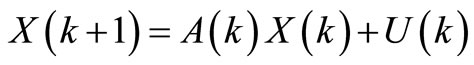 (1)
(1)
where  represents the collaborative control signal and where A(k) is the state transition matrix. There are several ways to define this collaborative signal. In order to keep the system simple and easy to be implemented in robotics, we assume that
  is a weighted sum of the human signal and the ANM signal. Hence,
 (2)
(2)
where:
 is the current stage (the index of the current point on the sub-trajectory);
 ;
;
where x(k) and y(k) are the platform coordinates in a reference frame;  is the platform orientation.
 where
where  is the ANM control signal change rate on x-axis;
  is the ANM control signal change rate on y-axis;
  is the ANM orientation change rate;
 where
where is the HCS on x-axis;
  is the HCS on y-axis;
  is the HCS for orientation change rate;
 (3)
(3)
 (4)
(4)
 (5)
(5)
 is the time between two consecutive stages.
In order to generate smooth motion for the platform, the SL should avoid large variation on  magnitude. Furthermore, the deviation between the platform configuration
  and the reference configuration
  at stage
  should be minimized in order to allow the platform to follow this reference path. One way to take into account all these requirements when generating the ANM sequence of configuration change rate
  is the formulation of an optimization problem. The following functional (used by the SL) takes into account the previously mentioned requirements:
 (6)
(6)
where:
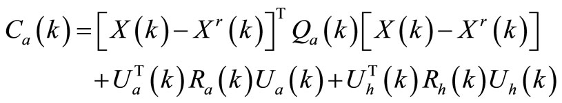 (7)
(7)
 (8)
(8)
 represents the ANM reference configuration at stage
  obtained by computing the sub-trajectory.
 is a
is a  symmetric and positive semidefinite matrix that penalizes the deviation between the state vector and the reference vector at stage
 ;
;
 is a
is a  symmetric and positive definite matrix that penalizes large ANM control signal at stage
 ;
;
 is a
is a  symmetric and positive definite matrix that penalizes large HCS at stage
 ;
;
The optimization horizon is .
.
The optimal sequence  is the sequence
  which minimizes the functional (6) under the constraint (1).
2.2.2. Solving the Planning Problem
In order to solve the problem, we assume that:
1) The configuration is fully observable to the ANM and the initial configuration  is known.
2) The human control signal  is known. In practice, this signal varies slowly and can then be approximated by a constant function within a short elapsed time
 .
.
3) The geometric sub-trajectory is realizable; all involved configurations on this trajectory are reachable individually.
The Hamiltonian of the system is described by the following equation:
 (9)
(9)
Using the minimum principle, we obtain the following expressions:
 (10)
(10)
and
 (11)
(11)
with the following boundary condition:
 (12)
(12)
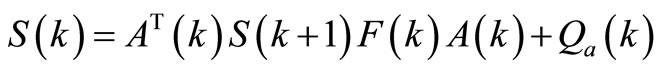
By applying optimal control theory, the following results are obtained:
 (13)
(13)
where:
 (14)
(14)
 (15)
(15)
 (16)
(16)
 (17)
(17)
 (18)
(18)
 (19)
(19)
According to Equation (2), the collaborative control signal is represented by:
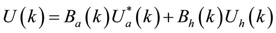
The planning law represented by Equation (13) is linear. Furthermore,  is a function of
  which values are set by the DL according to the confidence on the selected maneuver. Hence, if DL does not have a good confidence on the selected maneuver,
 . Thus, according to Equations (14), (16) and (17), the ANM control signal
 . The collaborative control signal
 , according to Equation (2).
2.3. Execution Layer
We assume that the robotic platform state  is represented by its configuration expressed in a reference frame (working space). The platform configuration consists of its position
  and its orientation
  in this frame as shown in Figure 2. Note that
  is the angle between x-axis and v-axis (Figure 2).
The EL input signal  is a weighted sum of the two control signals where the first control signal
  comes from the human. This signal represents the rate of configuration change the human would like to apply to the platform. The second control signal
 , provided by the ANM, represents the rate of configuration change to apply to the platform in order to achieve the plan given by the ANM Sequencer Layer (second layer represented in Figure 1). Hence,
  can be taught as the humanANM team configuration change to apply to the platform. Knowing the current configuration
  and
and , the desired configuration is computed using the platform dynamics. The EL, in the traditional three-layer architecture, is designed to be tightly coupled with sensors and actuators. It receives the sequence of configurations
  from the SL as the set points and

Figure 2. Navigation environment.
uses a pose tracking algorithm in order to minimize the deviation of the  and the measured platform configuration
 . Many methods exist to solve the controller problem when the involved platform is a wheeled robot [23-25]. Recently, Lyapunov based approaches has been proposed [26,27] . In this paper, a differentially driven robotic platform model is used [24]. Since the EL is decoupled with the upper layers, any other model can be used with a little modification of the architecture.
3. Simulation
3.1. Collaboration Planning Simulation
The goal of the simulation is to test the proposed Sequencer Layer planning method with the collaborative three layer architecture.
3.2. Simulation Scenario
A human wishes to drive a robotic platform from point A to point B as illustrated in Figure 3 by following the solid line trajectory. However, an obstacle is present on this trajectory. The goal of the ANM is to allow the team to avoid this obstacle by following trajectory represented by a dashed line. This trajectory is generated by the DL. We ran two different simulations in order to explain the influence of  on the collaborative planning. In the first simulation, all ANM functional matrices were set to identity matrices except the matrix
  which is set to
  (
( is a well-dimension unit matrix). By reducing the value of
 , the ANM control signal is less penalized. Hence, the ANM could adequately contribute to the team collaborative planning. In the second simulation, the ANM control signal is heavily penalized. For this case, the value of
  is set to
 . Simulations were done with
 , for all
  and the planning horizon
  is set to 500.
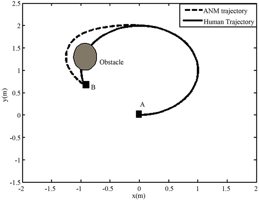
Figure 3. Simulation result scenario.
 .
.
3.3. Simulation Results
3.3.1. Case of ANM Full Contribution
We show in Figure 4 the result of the simulation when the ANM control signal is less penalized. This is the ANM Full Contribution mode. Although the presence of the human trajectory (solid line in Figure 3), the trajectory followed by the team is the same as the DL trajectory (Figure 4).
In Figure 5, we show the three control signal dynamics along x-axis: ,
,  and
and  are expressed in the reference frame. Whereas in Figure 6, the three control signal (
 ,
, and
and ) along y-axis are shown. For both figures, the contribution of the ANM is null until stage 300. Hence, the team trajectory is exactly the same as the human trajectory. From stage 300 to the end of the simulation, the team trajectory must follow

Figure 4. Simulation result with full ANM contribution.
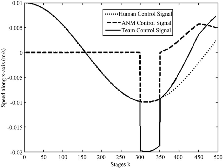
Figure 5. Control signals along x-axis with full ANM contribution.
the DL suggested trajectory in order to properly avoid the obstacle. To achieve this behaviour, the ANM uses the collaborative planning method proposed in Section 2.2.2. The ANM plan along x-axis and y-axis are respectively represented by the dashed lines in Figures 5 and 6. As a result, the team control signal (solid lines) which is also the collaborative signal is the required control signal in order to follow the DL trajectory.
3.3.2. Case of Manual Robotic Platform Control
When the ANM signal is heavily penalized, the architectture behaves as if the human is the unique controller of the platform. This result is shown in Figure 7. Notice that the team trajectory is the same as the human trajectory. Hence, the obstacle is not avoided.
The analysis of several control signals of this simulation (see Figures 8 and 9) reveals that the ANM control signal is very small.

Figure 6. Control signals along y-axis with full ANM contribution
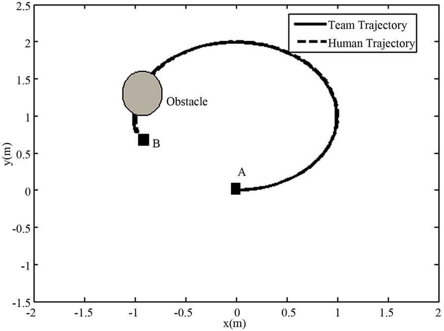
Figure 7. Control simulation result with No ANM contribution.
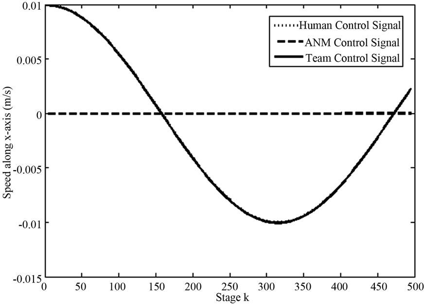
Figure 8. Control signals along x-axis with No ANM contribution.
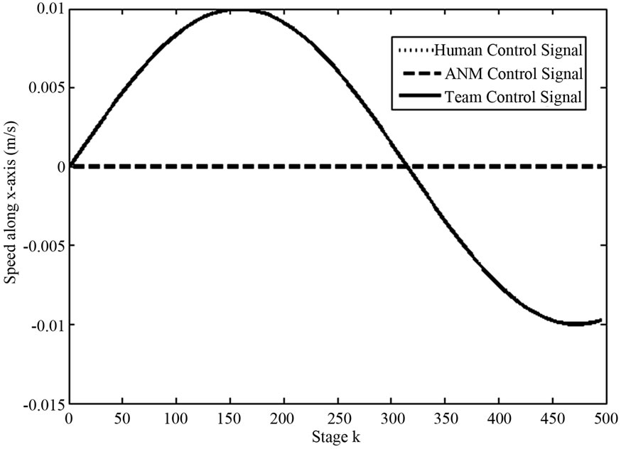
Figure 9. Signals along y-axis with No ANM contribution.
4. Discussion
One assumption of the proposed collaborative planning is based on the full knowledge of the human control signal during the planning period (between  and
and ). In practice, this assumption may not be valid. However, in the Figure 10, we show that even if the planning horizon is set to 1 (there is no need for knowing future human control signal), by selecting the appropriate value of
 , the trajectory followed by the team is quiet the same as if the planning horizon was greater than 1. The result presented in Figure 10 is obtained with
 .
.
It is interesting to notice that the proposed Sequencer Layer can be used with any decision-making process that provides a sequence of way-points which represents the navigation task sub goals. If the way-points are too distant from each other, the planning horizon  in the Sequencer Layer can be set to 1. Furthermore, a non holonomic constraint can be integrated in the formulation of the optimization problem in order to produce the ANM plans.
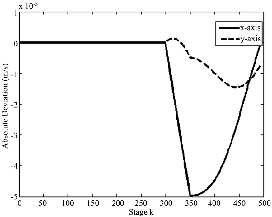
Figure 10. Deviation between trajectories obtained for M = 1 and M = 500.
5. Conclusion
A new Human-Navigation Module collaborative architecture that involves the human intervention at the deliberative and the sequencer layers, is presented in this paper. This architecture is based on the three-layer architecture. At the Deliberative Layer, the human control signal is analyzed in order to estimate the human maneuver during the navigation task. Based on this maneuver, the Deliberative Layer provides a sequence of waypoints to the Sequencer Layer which is also the planning layer. We proposed a method based on the optimal control theory that took into account the human plan and the Autonomous Navigation Module plan. The resulting collaborative plan is then executed in the Execution Layer which is responsible for non-linear platform control. The collaborative planning is simulated and results suggest that the penalty on the Autonomous Navigation Module control signal can be used to impose the platform operating mode among the following modes: Autonomous Navigation Module alone, Human Driven Mode alone or as any combination of the two previous modes. The proposed architecture could be used in applications such as telerobotic, smart wheelchair and unmanned vehicle collaborative navigation.
6. Acknowledgements
This work has been supported by the Natural Science and Engineering Research Council of Canada (Scholarship No BESC D3-348674-2007). The author would like to thank Pr. Paul Cohen from Ecole Polytechnique de Montreal.
REFERENCES
- M. Pantic, A. Pentland, A. Nijholt and T. S. Huang, “Human Computing and Machine Understanding of Human Behavior: A Survey,” Lecture Notes in Computer Science, 4451 NAI, Hyderabad, 2007, pp. 47-71,
- M. Chatterjee, “Design Research: Building Human-Centered System,” IEEE International Professional Communication Conference (IPCC 2007), Seattle, 1-3 October 2007, pp. 453-458.
- J.-M. Hoc, “Towards a Cognitive Approach to HumanMachine Cooperation in Dynamic Situations,” International Journal of Human Computer Studies, Vol. 54, No. 4, 2001, pp. 509-540.
- S. Krysztof, “Control of a Team of Mobile Robots Based on Non-Ccoperative Equilibra with Partial Coordination,” International Journal Applied Mathematic Computer Science, Vol. 15, No. 1, 2005, pp. 89-97.
- K. Sousso, B. Patrice and C. Paul, “Architecture for Human-Robot Collaborative Navigation,” International Conference on Health Informatics, Valencia, 20 January 2010, pp. 316-323.
- S. Katsura and K. Ohnishi, “Human Cooperative Wheelchair for Haptic Interaction Based on Dual Compliance Control,” IEEE Transactions on Industrial Electronics, Vol. 51, No. 1, 2004, pp. 221-228.
- Z. Qiang, B. Rebsamen, E. Burdet and L. T. Chee, “A Collaborative Wheelchair System,” IEEE Transactions on Neural Systems and Rehabilitation Engineering, Vol. 16, No. 2, 2008, pp. 161-170.
- C. Urdiales, A. Poncela, I. Sanchez-Tato, F. Galluppi, M. Olivetti and F. Sandoval, “Efficiency Based Reactive Shared Control for Collaborative Human/Robot Navigation,” Proceedings of the 2007 IEEE/RSJ International Conference on Intelligent Robots and Systems, San Diego, 29 October-2 November 2007.
- T. Hamagami and H. Hirata, “Development of Intelligent Wheelchair Acquiring Autonomous, Cooperative, and Collaborative Behavior,” IEEE International Conference on Systems, Man and Cybernetics, The Hague, 10-13 October 2004, pp. 3525-3530.
- T. Taha, J. V. Miro and G. Dissanayake, “Wheelchair Driver Assistance and Intention Prediction Using POMDPs,” Proceedings of the 2007 International Conference on Intelligent Sensors, Sensor Networks and Information Processing, Melbourne, 3-6 December 2007, pp. 449-454. doi:10.1109/ISSNIP.2007.4496885
- Y. Qi, Z. Wang and Y. Huang, “A Non-Contact Eye-Gaze Tracking System for Human Computer Interaction,” Proceedings of the 2007 International Conference on Wavelet Analysis and Pattern Recognition, Beijing, 2-4 November 2008.
- A. Huntemann, E. Demeester, et al., “Bayesian Plan Recognition and Shared Control under Uncertainty: Assisting Wheelchair Drivers by Tracking Fine Motion Paths,” Proceedings of the 2007 IEEE/RSJ International Conference on Intelligent Robots and Systems, San Diego, 29 October-2 November 2007, pp. 3360-3366
- T. Okawa, E. Sato and T. Yamaguchi, “Information Support System with Case-Based Reasoning Using Motion Recognition in Human-Centered City” Proceedings of the SICE Annual Conference, Takamatsu, 17-20 September 2007, pp. 610-613.
- J. B. Cruz Jr., “Leader-Follower Strategies for Multilevel Systems,” IEEE Transactions on Automatic Control, Vol. 23, No. 2, 1978, pp. 244-255. doi:10.1109/TAC.1978.1101716
- M. Simaan and J. B. Cruz Jr., “On the Stackelberg Strategy in Nonzero-Sum Games,” Journal of Optimization Theory and Applications, Vol. 11, No. 5, 1973, pp. 533- 555. doi:10.1007/BF00935665
- Y. C. Ho, P. Luh and G. Olsder, “Control-Theoretic View on Incentives,” Automatica, Vol. 18, No. 2, 1982, pp. 167-179. doi:10.1016/0005-1098(82)90106-6
- H. J. Toby, Collett, et al., “Player 2.0: Toward a Practical Robot Programming Framework,” Proceedings of the Australasian Conference on Robotics and Automation (A CRA 2005), Sydney, 5-7 December 2005.
- A. B. Rodney, “A Robust Layered Control System for a Mobile Robot,” IEEE Journal on Robotics and Automation, Vol. 2, 1986, p. 1.
- G. Erann, R. P. Bonnasso, R. Murphy and A. Press, “On Three-Layer Architectures,” Artificial Intelligence and Mobile Robots, 1998, pp. 195-210.
- A. Lankenau, “Avoiding Mode Confusion in Service Robots: The Bremen Autonomous Wheelchair as an Example,” Proceedings of the 7th International Conference on Rehabilitation Robots, Evry, 25-27 April 2001, pp. 162- 167.
- S. Carberry, “Techniques for Plan Recognition,” User Modeling and User-Adapted Interaction, Vol. 11, No. 1-2, 2001, pp. 31-48. doi:10.1023/A:1011118925938
- J. Borenstein and Y. Koren, “The Vector Field Histogram-Fast Obstacle Avoidance for Mobilerobots,” IEEE Transactions on Robotics and Automation, Vol. 7, No. 3, 1991, pp. 278-288.
- J. J. Abbott and A. M. Okamura, “Stable Forbidden-Region Virtual Fixtures for Bilateral Telemanipulation,” Transactions of the ASME, Journal of Dynamic Systems, Measurement and Control, Vol. 128, No. 1, 2006, pp. 53- 64. doi:10.1115/1.2168163
- A. Astolfi, “Exponential Stabilization of a Wheeled Mobile Robot via Discontinuous Control,” Journal of Dynamic Systems, Measurement, and Control, Vol. 121, No. 1, 1999, pp. 121-126. doi:10.1115/1.2802429
- Y. Kanayama, K. Yoshihiko, F. Miyazaki and T. Noguchi, “A Stable Tracking Control Method for an Autonomous Mobile Robot,” Proceeding of 90 IEEE International Conference Robotics and Automation, Cincinnati, 13-18 May 1990, pp. 384-389. doi:10.1109/ROBOT.1990.126006
- S. Belkhous, A. Azzouzi, M. Saad, C. Nerguizian and V. Nerguizian, “A Novel Approach for Mobile Robot Navigation with Dynamic Obstacles Avoidance,” Journal of Intelligent and Robotic Systems, Vol. 44, 2005, pp. 187- 201. doi:10.1007/s10846-005-9010-8
- D. J. Balkcom and M. T. Mason, “Time Optimal Trajectories for Bounded Velocity Differential Drive Vehicles,” International Journal of Robotics Research, Vol. 21, No. 3, 2002, pp. 199-217. doi:10.1177/027836402320556403