International Journal of Medical Physics, Clinical Engineering and Radiation Oncology
Vol.05 No.04(2016), Article ID:71804,21 pages
10.4236/ijmpcero.2016.54025
An Overview of the Control System for Dose Delivery at the UCSF Dedicated Ocular Proton Beam
Inder K. Daftari1,2, Kavita K. Mishra1, Rajinder P. Singh1,2, Dan J. Shadoan1, Theodore L. Phillips1
1Department of Radiation Oncology, University of California San Francisco (UCSF), San Francisco, CA, USA
2Lawrence Berkeley National Laboratory (LBNL), Berkeley, CA, USA

Copyright © 2016 by authors and Scientific Research Publishing Inc.
This work is licensed under the Creative Commons Attribution International License (CC BY 4.0).
http://creativecommons.org/licenses/by/4.0/


Received: August 18, 2016; Accepted: November 4, 2016; Published: November 7, 2016
ABSTRACT
Since 1978, the University of California San Francisco (UCSF) Ocular Tumor Program has been using particle therapy for treating ocular patients with malignant as well as benign eye disease. Helium ion beams were used initially and were produced by two synchrotron-based systems: first by the 184-inch synchro-cyclotron and later by the Bevalac, at the Lawrence Berkeley National Laboratory (LBNL). Since 1994, protons, produced by a cyclotron-based system at the Crocker Nuclear Laboratory (CNL) Eye Treatment Facility (ETF), have been used for this purpose. The CNL cyclotron produces a 67.5 MeV beam, allowing for a uniquely homogeneous beam for eye treatment, without degradation of the beam or manipulation of the beam line. This paper describes, in detail, the control system for beam delivery, as implemented for measuring and delivering the radiation to ocular tumors at CNL. The control system allows for optimal delivery and rapid termination of the irradiation after the desired dose is achieved. In addition, several safeguard systems are discussed, as these are essential for such a system in the event of failure of software, electronics, or other hardware. The QA analysis shows that the total range of the proton beam is 30.7 ± 1.0 mm in water at iso-center. The beam distal penumbra (80% - 20%) is 1.1 mm for a range-modulated beam at a collimator to iso-center distance of 50 mm. Daily QA checks confirm that the range and modulation is within 0.1 mm. The beam flatness and symmetry in a 25 mm diameter beam are ±1% - 2%. Variation in the daily dosimetry system, as compared to standard dosimetry, is within ±3.5%, with a mean variation of 0.72(±1.9)% and 0.85(±2.3)% for segmented transmission ionization chambers IC1 (upstream) and IC2 (downstream), respectively. From May 1994 to the end of 2015, UCSF has treated 1838 proton ocular patients at the Davis ETF. During this period, no treatments were missed due to any cyclotron or control system failures. The overall performance, maintenance, and quality assurance of the cyclotron and the ocular control system have been excellent.
Keywords:
Proton Beam Therapy, Beam Delivery, Control System, Ocular Tumors

1. Introduction
Charged particles (i.e. protons, helium ions, carbon ions and neon ions) are uniquely suited for the treatment of head and neck tumors, including the orbit and eye [1] . For many years, various ions, including helium and neon beams, were used for medical purposes at the Lawrence Berkeley National Laboratory (LBNL), using the 184-inch synchro-cyclotron and the Bevalac accelerators. However, following the shutdown of the Bevalac in 1992 due to economic reasons, the University of California San Francisco (UCSF) medical program for treating ocular melanoma with charged particles was moved to the Crocker Nuclear Laboratory (CNL) cyclotron at Davis, California. The Bevalac-based control system was modified and integrated with the CNL cyclotron between 1992 and 1994. Since May 1994, we have been treating patients at the Eye Treatment Facility (ETF) at CNL, using the 76-inch cyclotron. Most of the detectors and instruments were transferred from the Bevalac at the Lawrence Berkeley National Laboratory to the Crocker cyclotron to continue the ocular therapy program.
Today, interest in proton beam therapy is growing in the United States as well as in Europe and Asia. While it is true that a number of commercially-made proton cyclotron facilities either have started treating patients or are in the commissioning phase [2] , the cost of such commercial facilities is staggering. This was the main reason for adapting an existing facility, such as the CNL cyclotron, for the treatment of ocular tumors. The second reason for the selection of the CNL cyclotron is that the 67.5 MeV beam produced by it does not have to be degraded before it can be used for treating ocular tumors. This is contrasted with the typically 250 MeV beam produced by a commercial facility that must be degraded to around 70 MeV to treat ocular tumors. Hence, the CNL cyclotron produces a high quality beam without the fragmentation produced by degrading a 250 MeV beam.
The treatment with charged particles of uveal melanoma, as well as other malignant and benign eye disease, is being used at specialized medical centers worldwide and is being considered at other upcoming centers [3] - [12] . To date, UCSF’s proton therapy program for eye tumors is one of only a few major centers with an active and long-es- tablished dedicated proton ocular beam line [13] in the United States and one of only 12 in the world.
Uveal melanoma is the most common primary intra-ocular malignancy in adults. Although enucleation had been the historical standard treatment for malignant tumors of the eye, it has largely been replaced, over the past several decades, by a variety of eye-conserving treatment modalities, including radiation by brachytherapy, stereotactic radiotherapy, and charged particle therapy [14] . By the late 1970s, particle irradiation, using either protons or helium ions, was being initiated at Harvard University-Massa- chusetts General Hospital (MGH) in Boston [5] [15] , and by the University of California, San Francisco, at the Lawrence Berkeley National Laboratory (UCSF-LBNL) in the Bay area [16] .
Charged particles lose energy by ionizing and exciting the electrons of the medium through which they pass. The depth-dose curve for charged particles exhibits a sharp peak, named the Bragg peak, followed by a sharp fall-off of the dose. Due to this sharp fall-off of the distal part of the Bragg-peak, and because of minimal scattering of the beam, the stopping region of the beam can be defined precisely. In contrast, radioactive plaques deliver a very high dose to the sclera, and to the base of the tumor, in order to achieve adequate treatment of the apex of the lesion, thereby delivering substantial doses of radiation to nearby tissues. The other advantage of using charged particles is that there is no radiation exposure to the medical personnel. Only one surgical procedure, involving no radioactive material, is needed for localizing the tumor for particles. In contrast, brachytherapy requires both insertion and removal of the plaque by surgery. These physical characteristics make charged particle therapy ideal for localized intra-ocular irradiation. Clinical studies at various institutions, including ours, have confirmed that charged particles treat eye tumors very effectively. High local control rates of more than 96%, along with low enucleation rates and other complication rates, have been achieved with charged particle beams at dedicated centers such as ours with proton ocular beams [9] [10] [11] [12] .
A small core LBNL team of physicists, engineers and technicians were involved in adapting the synchrotron-based Bevalac Biomed control system for eye treatments at the CNL cyclotron. The original Biomed control system at the Bevalac was designed for the cyclic structure of the beams produced by a synchrotron (the Bevalac). Obviously, this had to be changed to handle the continuous beams produced by the Crocker cyclotron, in addition to providing new software to handle the new interface to the Crocker cyclotron. Furthermore, new software for the treatment of eye tumors had to be written for the Crocker version of the control system to replace the existing software that handled the wobbler at the Bevalac. The resulting Crocker version of the control system was assembled and tested with simulation at LBNL. The only new electronics hardware for the Crocker cyclotron system was the interface to the accelerator, the original Irradiation Control Chassis (ICC). This chassis was the heart of the UCSF-Crocker Eye Therapy control system. Experience over the years with the Eye Therapy control system, and especially the complexity of the original Irradiation Control Chassis, resulted in a number of lessons being learned. First, since 1978, there were several generations of hardware and software developed by LBNL personnel with resultant complexity and limited personnel with institutional knowledge. Second, there were a limited number of replacement and spare parts. Third, the wearing parts needed increasing maintenance (e.g. CAMAC power supplies, etc.). Finally, it was discovered that the prints for the original Irradiation Control Chassis in the LBNL print room did not match the actual installed hardware, and that the prints could not be used to make a duplicate of the original Irradiation Control Chassis or to trouble-shoot it in the event of a failure.
In order to develop and maintain a long-term sustainability plan for the control system, a program to upgrade the system was started in 2006 with some constraints: a) operation must not suffer; b) existing functionality must be preserved; and c) operational safety must be guaranteed. The main motivation for the upgrade was to carry out a reverse engineering job:
1) To produce and update the documentation/prints for older devices to understand the inner working of these devices, to develop maintenance instructions, to create an improved paradigm, and to replace incomplete or outdated information/certification; and
2) To build a spare Irradiation Control Chassis that would accept the same cables that plugged into the original chassis and would maintain the functionality of the original Irradiation Control Chassis.
The reverse engineering process resulted in an updated set of prints for the original Irradiation Control Chassis. In the event that it is ever necessary to fall back to the original Irradiation Control Chassis, the updated set of prints will be of crucial importance in maintaining the control system.
This upgrade was started in 2006 and finally completed in 2014. The new Irradiation Control Chassis incorporated not only all the functions provided by the original Irradiation Control Chassis, but also achieved a significant consolidation. It not only implemented all the features of the original Irradiation Control Chassis, but also incorporated the functions provided by several single-width CAMAC modules in the existing system, like the 1 MHz clock and the two dose-rate modules, in addition to a chassis that provided an interface to several hardware interlocks, like the neutron monitor.
The objective of the present paper is to describe the Biomedical control system as adapted for Eye Therapy at CNL, along with its modifications and its performance, during the years since 1994.
The control system was designed to monitor and control the proton beam in one or more rooms where irradiations were to be carried out. While the control system has the ability to handle irradiations in multiple treatment rooms, this feature is obviously not being used at the Crocker ETF, as this has only a single treatment room. The goal was to achieve reliable and reproducible operation. Safety, reproducibility, and accurate dose measurements were of paramount importance.
The main elements which comprise proton beam therapy based at a cyclotron are as follows:
1) A cyclotron or synchro-cyclotron, producing a proton beam between 70 MeV and 250 MeV.
2) A beam transport system to the treatment room, fitted either with an iso-centric gantry or a horizontal beam line.
3) A patient positioner.
4) A global safety management system, independent of the control system. This safety management system uses a combination of hardwired interlocks and independent programmable logic controllers to achieve safety levels meeting current application standards. We describe below the horizontal beam line at the CNL cyclotron.
2. Beam Line
2.1. Beam Transport
The 76-inch isochronous variable-energy cyclotron accelerates mono-energetic protons in the range between 2 MeV and 67.5 MeV. The eye therapy facility uses the 67.5 MeV beam. After exiting the cyclotron, the beam is focused by two quadrupole magnets with a 10 cm aperture and a maximum gradient of 0.7 KG/cm. The beam is then steered by X-Y dipole magnets to the center of the 10 cm aluminum beam pipe. All beam pipes are evacuated to 1 × 10⁻⁵ Torr by turbo pumps. A 40-inch dipole magnet deflects the beam to any of the 6 beam lines at the CNL cyclotron. The beam line at 9˚ transports the beam to the eye therapy cave, and all magnetic elements in the transport system after the bending magnet are off. The cyclotron radial beam emittance is 55 mm-mrad. The transport system, as used for the eye therapy line, has a 70% - 90% transparency with a beam cross section of less than 15 × 15 mm2 at the target end.
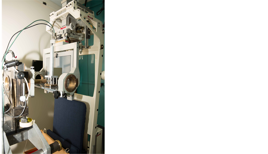
The eye beam line was set up to generate small proton fields to be used for the treatment of patients with ocular tumors, so no scattering system was adopted to broaden the beam. The eye beam line set up is illustrated in Figure 1. The beam line was designed to meet the specification of producing a 5 cm field diameter having a uniformity of ±3%. The vacuum beam pipe ends at the entrance to the treatment room. The beam extraction from the cyclotron is optimized at beam stop 2b and the beam position in the horizontal and vertical planes is measured with wire chamber 1 (WC1), which is placed downstream of the 40-inch bending magnet. The beam size and beam position in the treatment room are monitored by wire chamber 2 (WC2). WC1 and WC2 each have 2 orthogonal planes with 2 mm and 6 mm wire spacing, respectively. WC1 and WC2 are part of the control system.
2.2. Beam Monitoring and Dosimetry System
There are three primary dose monitors. The secondary emission monitor (SEM) [17] is placed at beam stop 4 and measures the intensity of the beam. It consists of an alternating stack of high voltage foils and collection foils of aluminum. They are placed in a vacuum chamber made of stainless steel with aluminum vacuum windows. The whole chamber is placed in vacuum. The aluminum foils are held between two supporting rings of ceramic material. The SEM provides beam detection which does not saturate at any achievable beam current. Two segmented transmission ionization chambers, IC1 and IC2, [18] define the central beam axis and provide yield information about the size and intensity of the circular field. IC1 and IC2 each have two foils, separated by a high voltage foil. One foil is divided into four quadrants, which measure the beam position (Left/Right and Up/Down) and the dose. The other foil is divided into 7 rings, which give the beam width. These chambers measure the dose 179 cm and 50 cm upstream

Figure 1. Layout of ocular beam line at UCSF-CNL Eye Treatment Facility. The beam, after entering the treatment room, passes through several devices before radiating the ocular tumor at the iso-center.
from the iso-center. All three detectors are monitored by electronic hardware as well as by the computer. The space between IC1 and IC2 is 129 cm. The SEM, IC1 and IC2 collect the ionization produced by the proton beam and convert it to NIM pulses with recycling integrators. These pulses are counted by preset scalers, 12-channel LeCroy scalers and Ortec scalers. The preset scalers and the 12-channel LeCroy scalers are read by the MicroVAX 3500 computer via CAMAC.
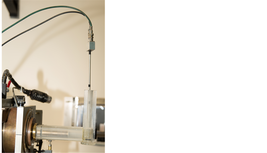
A range modulator [19] made from Lucite is located just after IC1. It is followed by a variable water column, which permits measurements to be made at various depths of penetration [20] . The water column consists of a piston in a cylinder connected to a water reservoir. The water in the path of the beam is contained between thin Lucite windows at the ends of the cylinder. The second Lucite window is connected to a movable piston. The amount of water between the windows is determined by the separation of the windows. An encoder reads the position of the windows to an accuracy of 0.1 mm. A brass collimator with a circular opening of 3.5 cm at the center defines the beam size at WC2, IC1 and IC2. The SEM, IC1 and IC2 monitor the dose delivered to the patient. A large patient shield made of aluminum is placed between IC2 and the patient assembly. The patient assembly system consists of a patient-specific collimator made of brass, a closed circuit TV (CCTV) system, a fixation light and an infrared light. The final patient-specific collimator, 5-cm from the iso-center, shapes the beam to a particular patient treatment field.
The chair is placed at the iso-center for final positioning. A head holder is attached to the chair and is used to position the patient’s head. The base of the chair can be rotated through 360˚. The chair moves in three orthogonal directions. There are two x-ray tubes, one placed in the posterior direction, just behind the chair, and one in the lateral direction. There are two flat panel digital imagers [21] . The digital panel in the anterior-posterior direction is placed on the beam line at a fixed target-to-image distance of 119 cm. It is attached to the patient assembly system. This imager is mounted on an air piston and interlocked to the X-ray unit. When making an exposure, the imager is in-line with the center of the focal spot and with the iso-center. When the X-ray enable trigger is depressed, the imager moves up and stops at the required position. When the X-ray button is released, the imager returns to the parked position, which is outside of the radiation field. The imager in the lateral direction is placed at a fixed target-to- image distance of 200 cm, as shown in Figure 1.
3. Control System
The eye therapy control system was modified from the Bevalac Biomedical control system [22] at LBNL. The control system is a hardware/software system used for the delivery, measurement and monitoring of the proton beam for UCSF patient treatments at Crocker Nuclear Laboratory. It consists of various procedures, with software and hardware safety features, which are described below. A block diagram of the control system is illustrated in Figure 2.
3.1. Software Procedures
There are several software procedures including: 1) creating and invoking a setup file; 2) beam tuning; 3) acquiring and displaying a Bragg curve to check the range of the beam; 4) beam calibration; and 5) the patient treatment procedure, which includes: a) handling and recovery from the interruption of a patient treatment; b) beam clamp (beam plug stays out) and c) handling and recovery from a power failure, in which case the beam plugs and stops are inserted.
3.2. Beam Tuning and Bragg Curve Related Procedures
On each treatment day, the two wire chambers (WC1 and WC2) monitor the beam position. Correct tuning of the beam is essential for achieving the desired accuracy and repeatability of the delivered dose. The wire chambers allow tuning of the beam to get the correct shape of the beam profile in the x- and y-directions. Since the initial shape of the beam is critical for obtaining the right dosimetry, a comparison of the current beam profile with a standard profile is displayed, to assist the operator with tuning the beam. Computer-driven display terminals are placed at both, the cyclotron control room and the Eye therapy control console. Figures 3(a)-(d) show the beam profile in the x- and y-directions from WC1 and WC2. The solid smooth curve is the desired beam profile and the dots are the positions of the beam as obtained by tuning. In addition, the centroid of the beam can be aligned relative to the axis used to position the pa-
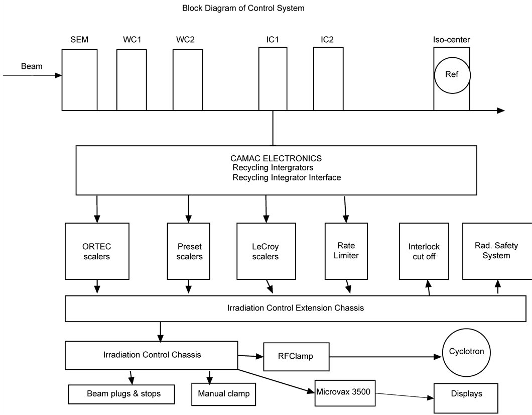
Figure 2. Block diagram of control system, which shows the layout of detectors, recycling integrators, distribution chassis, computer interface, computer and scalers.
tient. In Figure 3, wire chamber 1 (WC1) is in vacuum and wire chamber 2 (WC2) is just at the entrance of treatment room. Both wire chambers have wires in two orthogonal planes.
After tuning the beam to the desired position, various checks are made. The Bragg curve and 2.0 cm spread-out-Bragg Peak (SOBP) are measured daily by varying the water in the water column and obtaining the ratio of the charge between IC1 and IC2. Figure 4 shows the proton depth dose as measured in the water column by measuring the ionization ratio between IC1 and IC2. It is observed from Figure 4 that the un- modulated Bragg peak has a range of 30 mm and peak to plateau ratio of 3.8:1 and a width of 5 mm at full width at half maximum (FWHM).
3.3. Calibration and Patient Treatment Procedures
The calibration of the dosimetry system involves daily, standard and patient calibra-

Figure 3. Wire chamber 1 (WC1) is in vacuum and wire chamber 2 (WC2) is just at the entrance of the treatment room. Both wire chambers have wires in two orthogonal planes. The space between the wires is 2 mm for WC1 and 6 mm for WC2. Figures 3(a)-(d) show the desired profile of the beam (solid curve) and the current beam position (solid dots).
tions. The purpose of the calibration is to obtain the number of corrected counts on various detectors for a unit of dose delivered at iso-center.
The daily calibration is performed at the beginning of each treatment day by using a uniform circular radiation field of 2.5 cm diameter and a standard propeller of 2.0 cm at a standard depth in a phantom, as shown in Figure 5(a). The response of each detector (SEM, IC1 and IC2) is measured versus the response of a calibrated thimble ionization chamber (0.1 cc Far West). This data is compared with the standard dosimetry
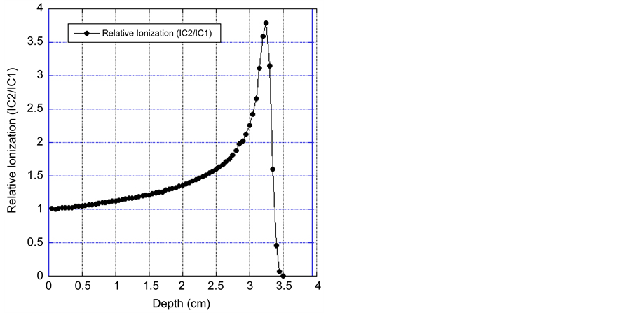
Figure 4. Depth dose curve of 67.5 MeV Proton beam, as obtained by varying the water in the water column and measuring the charge ratio of IC1 and IC2.
 (a) (b)
Figure 5. (a) shows the setup for doing the daily dosimetry. The ionization chamber is at a constant depth, which corresponds to the middle of the 2.0 cm spread-out-Bragg peak; (b) shows the setup for doing the patient calibration. The reference ionization chamber is placed at a depth which corresponds to the middle of the spread-out-Bragg peak behind a suitable tissue-equiva- lent material at a depth equal to the depth of the tumor in the patient.
data obtained on a six-month basis. The phantom consists of a plastic tube, which fits in a field-defining brass tube and an ionization chamber holder. A tissue-equivalent material is placed in the phantom, just before the ionization chamber. Consistent dosimetry is obtained with this system.
The patient calibration procedure involves producing the irradiation field to be used for the treatment and calibrates the dosimetry system against the reference chamber. The reference chamber is placed at a depth which corresponds to the middle of the SOBP behind a suitable tissue-equivalent material at a depth equal to the depth of the tumor in the patient, as shown in Figure 5(b).
The reference chamber is corrected for temperature and pressure. The treatment parameters are set up exactly according to the patient treatment. The responses of the SEM, IC1 and IC2 are calibrated in relation to the dose detected at the reference chamber. In the patient treatment procedure, the prescribed dose is then scaled to this calibration in order to obtain the cutoff values for each detector. The patient calibration data (i.e. number of counts per cGy for the SEM, IC1 and IC2), together with the daily calibration data and water column setting, are stored in a file for use during the actual patient treatment.
4. Control System Architecture
4.1. Control System Software
The control system software is comprised of a number of sub-systems and runs on a MicroVAX 3500, connected to two CAMAC crates via a multi-crate branch driver interface. Figure 6 is a schematic of the system architecture.
Independent hardware logic controls the time-points that drive the cyclic software components of the system and the inputs from a number of devices and software channel values which are derived from the hardware input. The most important of these inputs is, of course, whether the desired dose has been achieved, as measured by the ionization chambers and the SEM. Excessive neutron exposure (measured by a
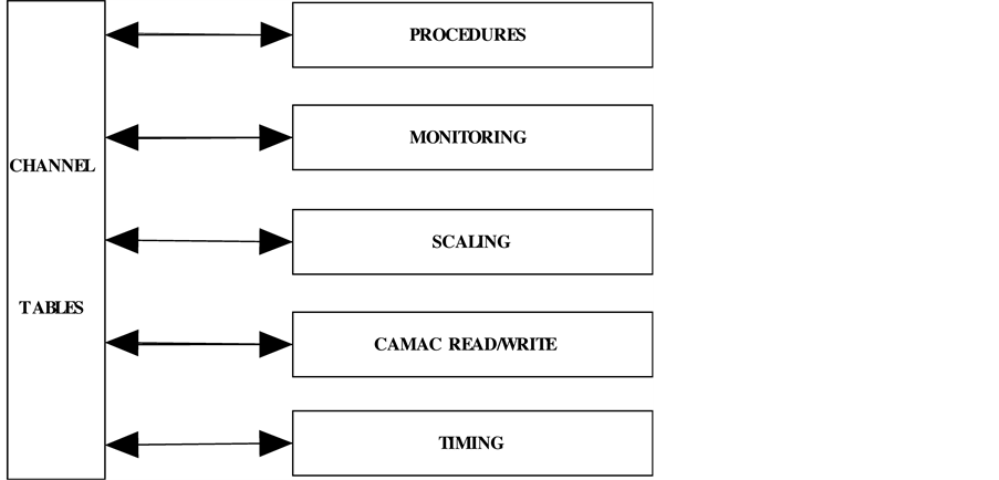
Figure 6. Schematic of the system architecture.
neutron monitor which is placed behind the patient chair), failure of the water column to achieve or maintain a desired position, or exceeding a particular dose rate, are examples of conditions which will cause a beam termination. A timing system provides time markers for control purposes as well as data acquisition and data analysis. In the Bevalac version of this control system, the beam-on and beam-off time points from the Bevalac comprised the timing system that was used to drive the cyclic components of the control system: the data read at the beam-on time-point gave the background counts for the various detectors and the corresponding background rate was calculated from this; the data read at the beam-off time-point gave the counts from the beam plus the background counts, and the background rate was used to get corrected spill counts, from which was calculated the dose delivered. In the Crocker version of this control system, the background rate is calculated before the beam plugs and beam stops are pulled to start the patient treatment, and is then used during the patient treatment to calculate the corrected counts and dose delivered. Since the cyclotron produces a continuous beam, the beam-on and beam-off time-points are replaced by time-points arbitrarily spaced about half a second apart, and these time-points are used to drive the cyclic components of the control system. The remainder of this section applies equally to the Bevalac and Crocker versions of this control system.
The Irradiation Control Chassis (Figure 7) contains a watchdog, which is armed at the beginning and end of each dosimetry cycle. If this signal is not acknowledged within 350 ms, the Irradiation Control Chassis asserts a signal that clamps the beam and in-
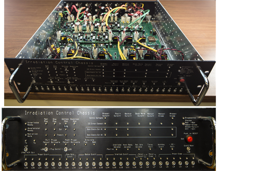
Figure 7. Shows the irradiation control chassis (both front and top views).
serts all beam stops and beam plugs. The normal sequence of events is that the software: a) detects the occurrence of the beginning or end of the dosimetry cycle and reads the state of the hardware (scalers, beam plug position, etc.); b) completes computations based on the data read; c) does any needed monitoring (e.g., position of the water column, etc.); and d) finally acknowledges the watchdog within the 350 ms window. Thus, the watchdog feature of the Irradiation Control Chassis protects the patient or other experimental target, not only in the event of a computer crash in the middle of an irradiation, but also in the event of any of several crucial cyclic software components aborting or hanging.
Data required for the operation of the control system is obtained via CAMAC and converted to appropriate units for use by higher-level routines. A channel table system provides all information on the names of the data and signals seen by the system, the computations required to obtain that data, and the methods by which parameters may be set. Most other structures in the control system are derived from the channel tables. A monitoring system ensures that control parameter values are correct, e.g. that a beam plug is out or that a parameter falls in a specified range (e.g. <1.0 Gy), and takes an appropriate action if a fault condition exists. A secondary hardware monitoring system, independent of the computer, ensures that the delivered dose does not exceed the desired dose. A display system provides the operator with information depicting the state of the control system and the values of critical parameters, such as the irradiation time, dose delivered, beam status, and fault conditions. The system, in addition, records information about the irradiation for the physician and support personnel, and sets external equipment to particular states specified by the user or by other control system components. A hardware circuit and accompanying computer software, called a watchdog system, check the functioning of the two time-points and, in the case of an acknowledgment failure within a specified time window by either one, terminates the beam. Control programs coordinate the various sub-systems to accomplish particular tasks, such as measuring Bragg curves, carrying out patient treatments, calibrating an irradiation, or exposing diagnostic X-ray film.
In addition to software monitoring of the delivered dose, an independent hardware system is used for monitoring the beam. For redundancy in measuring the dose delivered to the patient, the outputs from the SEM, IC1 and IC2 go to three separate scalers via three independent hardware paths. The primary scalers for terminating the beam upon delivery of the desired dose are countdown scalers, which are loaded with a preset value before the start of the treatment, and cause termination of the beam upon reaching zero. A second set of scalers, residing in CAMAC crates, are also read and monitored by the computer. A third type of scalers monitoring the dose of each detector is manually set and enabled by the Medical Physicist before an irradiation begins. This third type of scalers cannot be controlled by the computer or even be read by the computer. It provides a level of protection that is beyond all the software levels of safety provided by the control system.
4.2. Beam Termination and Interlocks
The beam can be terminated in three ways: a) Beam clamping, which turns the RF voltage down to stop the beam. This allows re-adjustment of the position of the patient and rapid resumption of the patient treatment. In this situation all the beam plugs are open and the beam stays in the cyclotron. It takes 50 msec to get the beam back; b) Manual cut-off, which turns the RF voltage down, inserts all plugs and stops, and can be used to end the treatment; and c) Crash-off, which is similar to manual cut-off, but also turns off the ion source. This is only used in emergencies. The control system interlocks include high voltage for ion chambers, correct position of the water column, and all beam plugs and beam stops in the beam.
5. Hardware/Software Sub-Systems
5.1. Hardware Monitoring Software (Watchdog)
The watchdog feature of the Irradiation Control Chassis was covered in an earlier section, and provides one of many levels of patient safety in this control system. The other levels of patient safety are covered in some of the remaining sub-sections, below.
5.2. Software Monitoring Hardware/Software
At the beginning and end of each dosimetry cycle, the software checks the position of the water column, the position of the beam stops and the beam plugs, etc., and allows the irradiation to continue if all the hardware is as expected. If any of these checks fails, the treatment program clamps the beam and inserts all beam stops and beam plugs, interrupts the patient treatment and saves all the data necessary to resume the interrupted treatment later.
At the end of each dosimetry cycle, the patient treatment procedure checks if the dose delivered as seen by the SEM, IC1 or IC2 exceeds the desired dose. If so, it clamps the beam and inserts all beam stops and beam plugs and ends the patient treatment.
5.3. Hardware Monitoring Delivered Dose
There are multiple preset and manual (Ortec) scalers dedicated to patient treatments. These scalers are connected to different dosimeters via independent hardware paths. This protects the patient in the event of failure of a single dosimeter or a failure at a single point along the hardware path to a particular preset scaler. The preset scalers are loaded before the beam stops and beam plugs are pulled to start a patient treatment. This protects the patient in the event that the program carrying out the patient treatment aborts or hangs after having pulled the beam stops and beam plugs.
The manual scalers are connected to different dosimeters via independent hardware paths. Unlike the preset scalers, however, the computer has no way of loading or even reading the manual scalers. The program that carries out patient treatments prompts the Medical Physicist with values to manually load into the manual scalers. The Medical Physicist loads the manual scalers and enables them. The manual scalers are used as backups to all the computer-controlled cutoffs. Hence, the values loaded in them are 2% higher than the exact counts that would complete the patient treatment.
5.4. On-Line Diagnostics
The process of installing the ETF control system software includes starting up a diagnostic program. This diagnostic runs at a very low priority. It writes a certain bit- pattern into a CAMAC test module in each crate in the system and reads back the data that it wrote. If the data read back agrees with the data written, it goes on to the next bit pattern. If, however, the data read back does not agree with the data written, it asserts a hardware signal to clamp the beam and inserts all beam stops and beam plugs. This protects the patient in the event that the integrity of the data flowing to or from a particular CAMAC crate is somehow compromised, possibly because of a faulty CAMAC branch highway cable.
5.5. Recovering from an Interrupted Patient Treatment
If a patient treatment is interrupted by the insertion of the beam stops and beam plugs, the treatment program asks the Medical Physicist what to do. After the problem that interrupted the patient treatment has been corrected (possibly by just re-positioning the patient), the Medical Physicist can tell the program to continue with the interrupted treatment. In this case, the treatment program prompts the Medical Physicist with the new set of values to load into the manual preset scalers. When the Medical Physicist indicates that this has been done, the treatment program waits for the Medical Physicist to give the command to pull the beam stops and beam plugs, and continues with the interrupted patient treatment.
Sometimes, however, the problem that caused the interruption is not immediately correctable. For example, the patient is too sick to continue with the treatment, or the cyclotron has a fault that will take more than a very short time to fix. In this case, the Medical Physicist instructs the treatment program to exit. The treatment program then saves its internal state in a file in order to be able to resume the interrupted treatment at a later time. Each time the treatment program is entered, it asks the Medical Physicist whether a previously interrupted treatment is to be resumed. If so, it looks for the file containing the data that permits it to resume the previously interrupted treatment. Since it is possible that a computer crash could occur during a patient treatment, a snapshot of the state of the patient treatment program is written out to disk after each dosimetry cycle. When the ETF control system software is installed, one of the first things done is to check this snapshot. If the snapshot indicates that a patient treatment was in progress at the time of the computer crash, it writes the data comprising the interrupted patient treatment into a file. This makes it possible to subsequently resume the interrupted treatment.
5.6. Data Logging
For each irradiation done, the ETF control system software keeps a comprehensive record. Included in the data logged is the setup of the optical bench (the position and identification of each device), the dose delivered to each dosimeter, the setting of the range absorber, etc. In addition to this, the logged data also includes the total counts delivered to each dosimeter. This makes it possible to subsequently re-check the calculation of the delivered dose, if so desired. The only program that does not maintain this extensive record is the procedure that is used for tuning the beam. During the beam tuning procedure, the beam position, beam shape, beam stability, dose rate, etc., are observed and optimized. There is no need to keep a record of the tuning process. In addition to all of the above, the patient treatment program produces a one-page summary of each patient treatment carried out. The Medical Physicist has the option of printing this file for inclusion in the patient’s chart.
5.7. Hardware Features That Facilitate Software Testing
An important and useful feature of the control system is its simulation capability. A programmable circuit allows injection of charge into each element of each detector, which can then be read back by the control system as if produced by real beam. This hardware simulation has two components:
1) The first component is the simulation of the hardware signals for the position of the beam stops and beam plugs. When the simulate bit in the Irradiation Control Chassis is turned on, the real beam stops and beam plugs remain in the fully-in position, and, when the software sets the bit to pull the beam stops and beam plugs, the simulation section in the Irradiation Control Chassis clears the fully-in bits for both beam stops and both beam plugs, and sets the in-transit bits, and, after a delay that corresponds to the time that it takes for the real beam stops and beam plugs to reach the fully- out positions, the in-transit bits are turned off and the fully-out bits are set. By design, the software in the ETF control system does not know that it is the simulated bits that are being manipulated, and not the bits for the real beam stops and beam plugs. This makes it possible to test the ETF software without having to make up interlocks and use real beam for testing software.
2) The second component is the injection of current into all dosimeters when the simulate bit in the Irradiation Control Chassis is set and the simulated beam stops and beam plugs are all in the fully-out position. This is done only when the real beam stops and beam plugs are in the fully-in positions and the simulated beam stops and beam plugs are in the fully-out positions, and looks like real beam to the ETF control system software. A hardware interlock is used to protect against mixing simulated with real beam.
This hardware simulation feature was not only crucial in the conversion effort from the Bevalac to the CNL cyclotron, but it is also crucial for the ongoing maintenance of the ETF, as it allows for the testing of the ETF control system without requiring real beam. Thus, it is possible to run high-level procedures, like a daily calibration and a patient treatment, without requiring actual beam. These high-level procedures are run every day between one week of eye treatments and the next. This makes it possible to detect, and to deal with, fault conditions like the failure of the power supply of a CAMAC crate.
6. Performance
Over the past four decades, UCSF has treated 2185 ocular patients, including 1,838 proton patients at CNL, with excellent clinical outcomes. The CNL eye beam line has been used for patient treatments since May 1994. All patients completed their treatment courses. Table 1 summarizes the eye patients with various histologies treated from May 1994 to the end of 2015. The majority are uveal melanoma (UM) cases, followed by various other malignant and benign eye diseases.
Table 2 summarizes the characteristics of patients with uveal melanoma. Most of the UM patients were treated for posterior choroidal tumors. There were 259 ciliary body, 12 iris and 48 iris-ciliary body tumors. The average range of the proton beam used was 22.5 ± 4.7 mm and the tumor height varied from 0.5 mm to 18.3 mm with a mean of 5.3 ± 3.0 mm. The field width varied from 6 to 33 mm with a mean of 15.3 ± 4.1 mm. The age of UM patients varied from 13 to 95 years with a mean of 60.95 ± 14.4 years.
The QA analysis shows that the proton beam total range is 30.7 ± 1.0 mm in water at iso-center. The beam distal penumbra (80% - 20%) is 1.1 mm for a range-modulated beam at a collimator to iso-center distance of 50 mm. Daily QA checks confirm that the range and modulation is within 0.1 mm. The beam flatness and symmetry in a 25 mm diameter beam is ±1% - 2% and alignment of the imaging is 0.1 mm.
The variation in the daily dosimetry, as compared to standard dosimetry, remained within 3.5%, with a mean variation of (0.72 ± 1.9)% for IC1 and (0.85 ± 2.3)% for IC2, as is observed from Figure 8. The daily dosimetry of the system can vary due to: 1) beam tuning; 2) change of range; and 3) temperature and pressure. This data is compared with the standard dosimetry obtained on the day a particular patient treatment was calibrated. The ratio of these two calibrations (i.e. the day the patient treatment was first calibrated and on each treatment day) is then used to adjust the patient calibration.

Table 1. Patients treated at UCSF-CNL Eye Treatment Facility from May 1994 to December 2015.
Table 2. Characteristics of uveal melanoma patients treated at UCSF-CNL Eye Treatment Facility from May 1994 to December 2015.
If the calibration changes more than 3.5%, the patient calibration is repeated.
7. Conclusions
The safety of any radiation therapy facility depends on the control system. The true measure of the control system is determined by how the general functions in the system are implemented. Achieving the three basic principles of any control system e.g. fail- safe design, redundant design and fault-tolerant design depends on how, at each level, the various functions of the control system have been implemented, so that the most probable failures will result in a safe state.

Figure 8. Variation of daily calibrations (measured by IC1 and IC2) as compared to standard calibration. The daily calibration is performed on each treatment day and the standard calibration is performed every six months. The calibration data is obtained from January 2000 to December 2015.
The UCSF Ocular Proton Therapy Program is one of a select few major centers in the United States, and one of only 12 in the world, with an active and long-established dedicated proton ocular beam line to date. Over the past four decades, UCSF has treated 2185 patients with rare ocular tumors, including 1838 proton patients at CNL, with reliability and consistency and with a low rate of complications. This is because the 67.5 MeV proton beam produced by the Crocker cyclotron has minimal fragmentation and is ideal for the treatment of ocular tumors. The overall performance, maintenance, safety, and quality assurance of the proton ocular control system have been excellent, and have benefited from the multiple layers of hardware and software safety that were evolved in the Bevalac version of this control system from 1979 to 1992, and that were retained intact in the Crocker version. The control system for the Eye Therapy Facility has undergone continuous improvements over many years and the process of preventive maintenance and forward development is ongoing.
Acknowledgements
We wish to express our sincere gratitude for the support and cooperation given to this project by the staff of LBNL, Crocker Nuclear Laboratory, UC Davis, and the Department of Radiation Oncology, UC San Francisco. We acknowledge with gratitude the help provided by a number of colleagues: from LBNL: Bill Chu, Mark Nyman, T.R. Renner, Charlie Pascale, Jeff Gallup; from CNL: Carlos Castaneda, Tim Essert, Randy Kemmler, Brian Devine; and from UCSF: L. Verhey, P.L. Petti and J.R. Castro.
Cite this paper
Daftari, I.K., Mishra, K.K., Singh, R.P., Shadoan, D.J. and Phillips, T.L. (2016) An Overview of the Control System for Dose Delivery at the UCSF Dedicated Ocular Proton Beam. Inter- national Journal of Medical Physics, Clinical Engineering and Radiation Oncology, 5, 242-262. http://dx.doi.org/10.4236/ijmpcero.2016.54025
References
- 1. Castro, J.R. (1995) Results of Heavy-Ion Radiotherapy. Radiation and Environmental Biophysics, 34, 45-48. http://dx.doi.org/10.1007/BF01210545
- 2. Kitagawa, A., Fujita, T., Muramatsu, M., Biri, S. and Drentje, A.G. (2010) Review on Heavy Ion Radiotherapy Facilities and Related Ion Sources. Review of Scientific Instruments, 81, Article ID: 02B909. http://dx.doi.org/10.1063/1.3268510
- 3. Castro, J.R., Char, D.H., Petti, P.L., Daftari, I.K., Quivey, J.M., Singh, R.P., Blakely, E.L. and Phillips, T.L. (1997) 15 Years Experience with Helium Ion Radiotherapy for Uveal Melanoma. International Journal of Radiation Oncology, Biology, Physics, 39, 989-996.
http://dx.doi.org/10.1016/S0360-3016(97)00494-X - 4. Gragoudas, E.S. (2006) Proton Beam Irradiation of Uveal Melanomas: The First 30 Years the Weisenfeld Lecture. Investigative Ophthalmology & Visual Science, 47, 4666-4673.
http://dx.doi.org/10.1167/iovs.06-0659 - 5. Egger, E., Zografos, L., Schalenbourg, A., Beati, D., Bohringer, T., Chamot, L. and Goitein, M. (2003) Eye Retention after Proton Beam Radiotherapy for Uveal Melanoma. International Journal of Radiation Oncology, Biology, Physics, 55, 867-880.
http://dx.doi.org/10.1016/S0360-3016(02)04200-1 - 6. Chauvel, P., Courdi, A., Bruneton, J.N., Caujolle, J., Grange, J. and Diallo-Rosier, L. (1998) Proton Therapy of Uveal Melanomas in Nice: A 6.5-Year Follow-Up Study. Radiology, 209P, 401-402.
- 7. Hocht, S., Stark, R., Seiler, F., Heufelder, J., Bechrakis, N.E., Cordini, D., Marnitz, S., Kluge, H., Foerster, M.H. and Hinkelbein, W. (2005) Proton or Stereotactic Photon Irradiation for Posterior Uveal Melanoma? A Planning Intercomparison. Strahlentherapie und Onkologie, 181, 783-788. http://dx.doi.org/10.1007/s00066-005-1395-6
- 8. Bonnett, D.E., Kacperek, A., Sheen, M.A., Goodall, R. and Saxton, T.E. (1993) The 62 MEV Proton-Beam for the Treatment of Ocular Melanoma at Clatter Bridge. British Journal of Radiology, 66, 907-914. http://dx.doi.org/10.1259/0007-1285-66-790-907
- 9. Mishra, K.K., Quivey, J.M., Daftari, I.K., Weinberg, V., Cole, T.B., Patel, K., Castro, J.R., Phillips, T.L. and Char, D.H. (2015) Long-Term Results of the UCSF-LBNL Randomized Trial: Charged Particle with Helium Ion versus Iodine-125 Plaque Therapy for Choroidal and Ciliary Body Melanoma. International Journal of Radiation Oncology, Biology, Physics, 92, 376-383. http://dx.doi.org/10.1016/j.ijrobp.2015.01.029
- 10. Mishra, K.K., Daftari, I.K., Weinberg, V., Cole, T., Quivey, J.M., Castro, J.R., Phillips, T.L. and Char, D.H. (2013) Risk Factors for Neovascular Glaucoma after Proton Beam Therapy of Uveal Melanoma: A Detailed Analysis of Tumor and Dose-Volume Parameters. International Journal of Radiation Oncology, Biology, Physics, 87, 330-336.
http://dx.doi.org/10.1016/j.ijrobp.2013.05.051 - 11. Mishra K.K., Sou-Tung, C.-T. and Orton, C.G. (2016) Particle Therapy Is Ideal for the Treatment of Ocular Melanomas. Medical Physics, 43, 631-634.
http://dx.doi.org/10.1118/1.4939223 - 12. Zytkovicz, A., Daftari, I., Phillips, T.L., Chuang, C.F., Verhey, L. and Petti, P.L. (2007) Peripheral Dose in Ocular Treatments with Cyber Knife and Gamma Knife Radiosurgery Compared to Proton Radiotherapy. Physics in Medicine and Biology, 52, 5957-5971.
http://dx.doi.org/10.1088/0031-9155/52/19/016 - 13. Hrbacek, J., Mishra, K.K., Kacperek, A., Dendale, R., Nauraye, C., Auger, M., Herault, J., Daftari, I.K., Trofimov, A.V., Shih, H.A., et al. (2016) Practice Patterns Analysis of Ocular Proton Therapy Centers: The International OPTIC Survey. International Journal of Radiation Oncology, Biology, Physics, 95, 336-343.
http://dx.doi.org/10.1016/j.ijrobp.2016.01.040 - 14. Daftari, I.K., Petti, P.L., Shrieve, D.C. and Phillips, T.L. (2006) Newer Radiation Modalities for Choroidal Tumors. International Ophthalmology Clinics, 46, 69-79.
http://dx.doi.org/10.1097/01.iio.0000195863.79181.4f - 15. Constable, I.J., Goitein, M., Koehler, A.M. and Schmidt, R.A. (1976) Small-Field Irradiation of Monkey Eyes with Protons and Photons. Radiation Research, 65, 304-314.
http://dx.doi.org/10.2307/3574203 - 16. Saunders, W.M., Char, D.H., Quivey, J.M., Castro, J.R., Chen, G.T.Y., Collier, J.M., Cartigny, A., Blakely, E.A., Lyman, J.T., Zink, S.R. and Tobias, C.A. (1985) Precision, High-Dose Radiotherapy-Helium Ion Treatment of Uveal Melanoma. International Journal of Radiation Oncology, Biology, Physics, 11, 227-233.
http://dx.doi.org/10.1016/0360-3016(85)90143-9 - 17. Tautfest, G.W. and Fechter, H.R. (1955) Nonsaturable High-Energy Beam Monitor. Review of Scientific Instruments, 26, 229-231. http://dx.doi.org/10.1063/1.1771258
- 18. Renner, T.R., Chu, W.T., Ludewigt, B.A., Nyman, M.A. and Stradtner, R. (1989) Multisegmented Ionization-Chamber Dosimetry System for Light-Ion Beams. Nuclear Instruments and Methods in Physics Research Section A, 281, 640-648.
http://dx.doi.org/10.1016/0168-9002(89)91501-5 - 19. Petti, P.L., Lyman, J.T., Renner, T.R., Castro, J.R., Collier, J.M., Daftari, I.K. and Ludewigt, B.A. (1991) Design of Beam-Modulating Devices for Charged-Particle Therapy. Medical Physics, 18, 513-518. http://dx.doi.org/10.1118/1.596655
- 20. Tobias, C.A., Lyman, J.T., Chatterjee, A., Howard, J., Maccabee, H.D., Raju, R.R., Smith, A.R., Sperinde, J.M. and Welch, G.P. (1971) Radiological Physics Characteristic of Extracted Heavy Ion Beams of Bevatron. Science, 174, 1131-1134.
http://dx.doi.org/10.1126/science.174.4014.1131 - 21. Daftari, I.K., Essert, T. and Phillips, T.L. (2009) Application of Flat Panel Digital Imaging for Improvement of Ocular Melanoma Patient Set-Up in Proton Beam Therapy. Nuclear Instruments and Methods in Physics Research Section A, 598, 628-634.
http://dx.doi.org/10.1016/j.nima.2008.10.008 - 22. Renner, T., Nyman, M. and Singh, R.P. (1995) Control Systems for Ion Beam Radiotherapy Facilities. In: Linz, U., Ed., Ion Beams in Tumor Therapy, Chapman and Hall, London, 256-265.