Open Journal of Energy Efficiency
Vol.04 No.04(2015), Article ID:61751,8 pages
10.4236/ojee.2015.44008
Generation of Electric Power from Domestic Cooking System
Syed Ali Raza Shah1, Zahoor Ahmed2, Bashir Ahmed Leghari1, Wazir Muhammad Laghari2, Attaullah Khidrani2
1Department of Mechanical Engineering, Balochistan University of Engineering and Technology, Khuzdar, Pakistan
2Department of Electrical Engineering, Balochistan University of Engineering and Technology, Khuzdar, Pakistan

Copyright © 2015 by authors and Scientific Research Publishing Inc.
This work is licensed under the Creative Commons Attribution International License (CC BY).


Received 19 March 2015; accepted 4 December 2015; published 7 December 2015

ABSTRACT
This study work related with floating of an idea about conversion of reclaimed thermal energy from domestic cooking system into the electrical power. There were different techniques in use worldwide for harnessing the energy into the appropriate useful work and also to create efficient system for the energy conversion process. The ignorance in this regard might be due to the reason that this wastage did not cost too much for a single home on per day or per month basis, but it could be an ample amount of cost if integrated this loss for a whole city or on yearly bases for a single home. The idea in this work depended upon the recovery of waste heat from Pressure Cookers used in the houses for the domestic cooking purposes, and optimized the reclaimed thermal energy for the conversion into electric power. This research work related with losses of energy discussed and analyzed on the basis of thermo dynamically regarding (a) the wastage of thermal energy escaped through the system due to the spreading of exhaust vapors and taking away significant amount of thermal energy; (b) losses of enthalpy through the dissipate steam; (c) heat losses in the tubing from the Pressure Cooker to the turbine; (d) electric power produces from the system. In this work, new methods were advised, in order to reduce the losses of thermal energy from the system. It would open the venue for researchers to promote this new idea in near future.
Keywords:
Waste Heat, Pressure Cooker, Thermal Energy, Electric Power, Enthalpy Losses, Steam Turbine

1. Introduction
The every nation desires for self-sufficient in the sector of energy, as it plays a vital role in the economic development either in industrial area or in the domestic use. More over the rising in grassroots population throughout the world, it will adversely affect the resources and develops pressure on the basic amenities. They also rely on the energy sector for their likely-hood in future. Hence, demand of energy is increasing day by day. In order to over- come this issue and fulfill the requirement of energy demand in future, proper planning and development activities can be started in every sector immediately. The idea in this work depends upon the recovery of waste heat from the Pressure Cooker which uses in the houses for daily domestic cooking purpose, and optimizes the reclaimed thermal energy for the electric power [1] . Pressure Cooker dissipates the high temperature steam continuously during the entire process. The exhausted steam is more appropriately used to convert the enthalpy of the steam into electrical power energy through De-Laval’s turbine (a single stage, single nozzle steam turbine), and it is used for convenience in manufacturing. This set-up can be applied to the systems where cooking done on larger scales continuously like hotels and food companies, but it is not feasible to be adopted at domestic level because turbine alternator set-up makes the system complex and bulky [2] .
2. Design Procedure
The waste exhausted heat recovered from the Pressure Cooker was used for optimizing the efficiency of system and utilized the reclaimed thermal energy for conversion in to the electric power for specified given data. In this work study was focused upon the Pressure Cooker used for cooking food stuff or heating the potable water in the house daily. The calculation related with its design procedure is discussed as under.
2.1. Energy Available in the Fuel Gaseous
The fuel gas liberated an amount of energy in the form of fuel consumption rate by unit time from natural gas to the burner of Pressure Cooker. The measuring unit of energy is Joule or KJ and in case of gas consumed per unit time then it will be considered as KW [2] :
 (1)
(1)
In the above equation
 is equivalent to the rate of fuel consumption per time and measured in KW.
While:
 = Mass flow rate in Kg/sec:

The calorific value of any substance is to be considered to the heating value of that material. The quantity of heat liberated during the process of combustion for any of fuel; and measuring unit for energy/unit of time for the particular substance such as MJ/Kg. The various fuels have different calorific values as indicated in Table 1 [3] .
The Natural gas has methane (CH4) 85% to 90% as an ingredient, while the remaining other particles depends upon ethane, butane, propane, nitrogen, and CO2 etc. Hence it is clear from Table 1 that the Natural gas has Calorific value near about (55.5 MJ/Kg) as per consideration on the basis of methane. Since natural gas is not available in pure form and having sufficient amount of impurities and also keeping the other losses under consideration. Then it will be considered that the natural gas about 70% of its original mass will be available for the design calculation, hence the calorific value of natural gas is as under:

Table 1. Calorific values of common fuels.

The study was carried out through practical conduction on the gas cylinder. The gas cylinder was placed over the digital weight meter and fuel consumptions were observed after expiry of ten 10 seconds. The data was analyzed as per consumed mass of fuel per unit time. Hence the rate of fuel consumption was the actual power produced by the gas fuel for the burner. The
 was recorded during practical. Putting the calculated values in Equation (1), then the energy in the form of power calculated as:

2.2. Losses of Energy from the System
It was apparently revealed that without the economizing arrangement; the small amount of thermal energy was lost due to the absorption by the system and operating pressure vary from 3 - 9 KPa during the process. It is clear from Table 2 that the power released by the fuel gas supplied to the furnace amounting to (8.574 KW). Similarly on other hand the power losses by evaporation was (2.136 - 2.406 KW) as shown in Table 2.
The efficiency in percentage wise for the system without doing any economic planning can be estimated as mentioned below [3] .
 (2)
(2)

Hence, losses of thermal energy/second will be:

It is clear from the above discussion that 6.168 KJ of energy lost by each second from the system; therefore efficiency reduced to 28.15%, as shown in Figure 1, but that is very low, so it can be enhanced.

Figure 1. Power consumption rate.
Table 2. Thermal properties of steam.
3. Steps Suggested for Improvement of Efficiency
In order to improve the efficiency of the system; the under mentioned steps are suggested keeping some economical arrangements in the system.
3.1. Insulation of the System
It is proposed that to collect the energy of flue gases from the domestic Pressure Cooker at home then insulation may be provided in the system. It was suggested that a metallic shell with area considerably greater than the covered area of the burner including Pressure Cooker be fabricated around it. The maximum temperature will be in the space within the shell and between the walls of the Pressure Cooker, that will helps to raise the temperature up to the maximum level. The energy of flue gases can be trapped and utilized for heating the cooker. The external insulation of burner including pan with shell will prevent the loss of heat transfer through mode of conduction and convection to atmosphere as seen in Figure 2 [4] .
The influence of temperature and color of flame vary with type of fuel involved for combustion process. The variable absolute temperature values for different fuels react with air or O2 during the combustion process are mentioned below in Table 3.
The color of flames are depends upon the molecular constituents of the fuels. It is not necessary that the blue colored flames are every time considered to be scorching than yellow colored flames [5] . A light yellow flame causes the losses of heat to some level instead of blue flame, in order to overcome the losses and try to make the system efficient; then make arrangement for a decent sharp blue colored flame for the system. The orifice of nozzles for the burner must be fabricated considering the back pressure including the feeding rate of the fuels. In order to accomplish the good hot flame for the system; then make arrangement for efficient supply of fuel. Then domestically system became efficient by adopting these all above mentioned arrangement collectively (Figure 3 and Figure 4).

Figure 2. View of metallic shell for burner.
Table 3. Common temperature (K) values for different fuels.

Figure 3. Light yellow flame.

Figure 4. Blue flames.
3.2. Measuring Vapor Pressure
Here in this case the fuel gas supplied to the burner for providing the heat energy to the Pressure Cooker for evaporation process. A vapor pressure was measured through pressure gauge installed over the Pressure Cooker for getting the gauge pressure instantly. The Pressure Cooker shut down during the process of recording the value of gauge pressure. These recorded readings of pressure gauge were used for analysis the efficiency of the system. The online SPIRAX SPARCO calculator was used to find out other related properties such as flow rate of mass and power output etc. for steam tables as given in Table 4 [6] .
4. Improvement in Efficiency of the System
The Pressure Cooker is used for cooking the food stuff everywhere including towns as well as in big cities. In these systems there are many chances for losses of thermal energy from the surrounding and system became inefficient and uneconomical for the use of domestic purposes. The system has efficiency within the range of 20% - 30%. The economizing arrangements were made and calculated as shown in Table 4. The output power without the economizing arrangement was ranging from 2.136 to 2.406 KW as calculated power supplied was 8.547 under operating pressures between 3 - 9 KPa [7] . The exact calculation of reclaimed thermal energy is almost impossible due to the involvement of analysis of flue gases with variation in flame shapes. Therefore readings were directly obtained through software and observed with economizing arrangement under operating pressure that was 50.5 to 60.5 KPa having corresponding output powers between 4.303 - 4.847 KW. The new efficiency of the system can be improved up to:

5. Energy Analyses
The energy produced was not much enough in amounts. However, it was a useful for analyzing steam conditions
Table 4. Net effect after making the economizing arrangement.
for requirement of turbine design [8] . Moreover, the Wattmeter was attached with the alternator that provided the output parameters, which shows the effectiveness of the arrangements. The initial reading on the pressure gauge with the final reading on the wattmeter was used for calculations and it was included in Table 3. Since frictional and conductional losses from the exit point of steam from the Pressure Cooker to the turbine and alternator were neglected. Energy consumed to form steam by evaporating water was treated as the useful work of the system. Steam exhausted from the Pressure Cooker was the only output parameter [9] . The amount of the heat absorbed by the system and the efficiency of the system was improved by adopting the economizing arrangement on it. The study required to check the possibility of converting the steam enthalpy into electrical power by using a single nozzle De-Laval’s Turbine as shown in Figure 5. Laval developed a nozzle in 1890 in order to increase the working of the kinetic energy of the steam, rather than its pressure for steam jet to the supersonic speed.
The wattmeter reading practically finds out the efficiency of the whole mechanism. At the peak pressure conditions, the theoretical power output of the turbo-generated was estimated 347.10 W; but practically it came out 131.898W on the wattmeter as shown in Table 5.
The overall efficiency of tubing, nozzle, turbine and alternator calculated as under

This percentage is applied to all the values of the shaft power to calculate the actual output. The result shows that loss of 62% of available energy across the power generation setup that was obviously a result of non-pro- fessionalism and manufacturing limitations within the remote area.
6. Design Configuration of Steam Turbine
1. Power supplied by the Gaseous Fuel

2. Absolute pressure

3. Saturation temperature

4. Mass flow rate of steam

5. Enthalpy of saturated vapor

6. Specific volume of saturated vapor

7. Velocity of the steam outlet

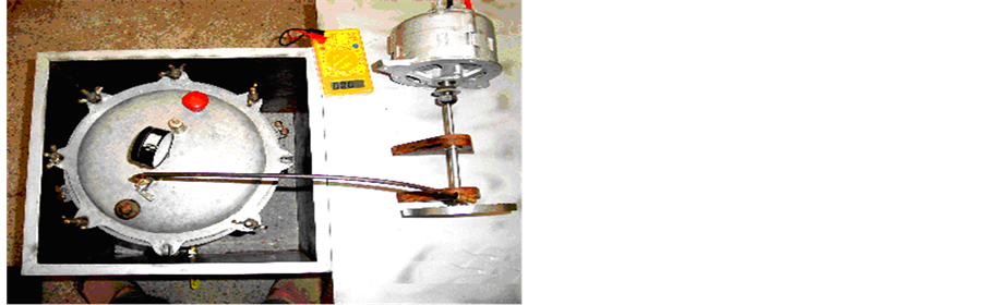
Figure 5. Energy conversion arrangements.
Table 5. Power output over shaft and in watt-meter.
8. Diameter of Jet

9. Area of Jet

10. Thermal power at steam outlet

11. Specific heat at constant pressure of steam
 convergent nozzle used
12. Kinetic energy of the steam before the nozzle:

13. Initial Mach number:

14. Velocity of steam beyond nozzle (28.57% converged):

15. Kinetic energy of the steam beyond the nozzle

16. Enthalpy of the steam beyond the nozzle

17. Temperature of the steam beyond the nozzle

18. Pressure drop through the nozzle

19. Mach number of the steam beyond the nozzle

20. Velocity of blade to the velocity of steam jet

21. Angle of blade

22. Specific heat ratio

23. Volume of the rim V = 0.000113 m3
24. Weight of the rim: W = 564.6723 gm
25. Blade height: h = 7 mm
26. Inlet angle

27. Outlet angle

28. Blade width: = 10 mm
29. Radius of curvature of the blade

30. Third angle of blade

31. Area of blade


32. Circumference of the Rim:

33. Number of blades = 45
34. Total mass of blades = 59.861 gm
35. Total mass of the turbine = 624.533 gm
36. Corresponding power at the shaft = 347.10 W
37. Diameter of shaft = 2.269 mm
38. Permissible Shear stress

39. Bending stress ( ) for the Shaft = 80

40. Length of shaft = 0.015 mm
7. Conclusion
This study work will address the problem for reclaiming of waste heat energy from the domestic Pressure Cooker used for cooking system and converts the same into the electric power. The efficiency of system is improved through proposed process and suggests to optimize the domestic cooking system for achieving the better efficiency and to save the thermal energy for future requirement.
Acknowledgements
The authors acknowledge the chairman and Incharge of Laboratories section, Mechanical Engineering Department, Balochistan University of Engineering & technology, Khuzdar, for providing the laboratory facilities.
Cite this paper
Syed AliRaza Shah,ZahoorAhmed,Bashir AhmedLeghari,Wazir MuhammadLaghari,AttaullahKhidrani, (2015) Generation of Electric Power from Domestic Cooking System. Open Journal of Energy Efficiency,04,69-76. doi: 10.4236/ojee.2015.44008
References
- 1. Domestic Waste Water Heat Recovery Device.
http://www.pera.com/website/clientsandcasestudies/creatingnewproductideas/ - 2. Liu, L.B., Fu, L. and Jiang, Y. (2010) Application of an Exhaust Heat Recovery System for Domestic Hot Water. Journal of Energy, 35, 1476-1413.
http://dx.doi.org/10.1016/j.energy.2009.12.004 - 3. De Paepe, M. and Theun, E. (2003) Heat Recovery System for Dishwashers. Journal of Applied Thermal Engineering, 23, 743-756.
http://dx.doi.org/10.1016/S1359-4311(03)00016-4 - 4. Lukitobudi, R., Akbarzadeh, A., Johnson, P.W. and Hendy, P. (1995) Design, Construction and Testing of a Thermo syphon Heat Exchanger for Medium Temperature Heat Recovery in Bakeries. Journal of Heat Recovery Systems and CHP, 15, 481-491.
http://dx.doi.org/10.1016/0890-4332(95)90057-8 - 5. Colangelo, G., de Risi, A. and Laforgia, D. (2006) Experimental Study of a Burner with High Temperature Heat Recovery System for TPV Applications. Journal of Energy Conversion and Management, 47, 1192-1206.
http://dx.doi.org/10.1016/j.enconman.2005.07.001 - 6. www.SPIRAXSPARCO.com
- 7. Noie-Baghban, S.H. and Majideian, G.R. (2000) Waste Heat Recovery Using Heat Pipe Heat Exchanger (HPHE) for Surgery Rooms in Hospitals. Journal of Thermal Engineering, 20, 1271-1282.
http://dx.doi.org/10.1016/S1359-4311(99)00092-7 - 8. El-Baky, M.A.A. and Mohamed, M.M. (2007) Heat Pipe Heat Exchanger for Heat Recovery in Air Conditioning. Journal of Applied Thermal Engineering, 27, 795-801.
http://dx.doi.org/10.1016/j.applthermaleng.2006.10.020 - 9. W.J. Kearton in His Book “Steam Turbine Theory and Practice”.