Open Journal of Applied Sciences
Vol.3 No.4(2013), Article ID:35004,4 pages DOI:10.4236/ojapps.2013.34039
Fast and Low Cost X-Ray Stereoradiography Displayed on a 3D Monitor
Department of Nuclear Engineering, Chulalongkorn University, Bangkok, Thailand
Email: *nares.c@chula.ac.th
Copyright © 2013 Akara Akaranate et al. This is an open access article distributed under the Creative Commons Attribution License, which permits unrestricted use, distribution, and reproduction in any medium, provided the original work is properly cited.
Received January 18, 2013; revised February 18, 2013; accepted February 25, 2013
Keywords: Radiographic Testing; X-Ray; Fluoroscopy; Stereoradiography; 3D Imaging; Gadolinium Oxysulfide
ABSTRACT
Conventional x-ray stereoradiography based on film radiography is not practical due to its inconvenient and time-consuming procedures. In this research, an image viewing system consisted of a 30 cm × 30 cm gadolinium oxysulfide (GOS) fluorescent screen and a Cannon 500D digital camera were designed and constructed for real-time and near real-time x-ray imaging. The camera was connected to a laptop computer via USB port to allow remote camera setting and control as well as view image on the computer. The system was tested with x-rays generated from a Rigaku x-ray tube for its response at various camera settings and exposure times. The image brightness increased with increasing of the camera ISO setting and with the exposure time as expected. To test the system performance, two test specimens were radiographed including a video camera and a floppy disk drive as well as two simulated specimens. Each of the test specimens was also radiographed at two positions by moving the specimens approximately 6 cm from the first position. The two radiographs of each specimen were then combined to make an anaglyph image that could be viewed in 3D on a normal LCD or LED monitor by using appropriate color glasses. When the two radiographs were combined to make MPO (multiple object) file format, it could be viewed in 3D on a 3D monitor with or without 3D glasses depending on type of the monitor. The developed system could be conveniently employed for routine inspection of a specimen both in 2D and 3D within a minute.
1. Introduction
Radiographic testing (RT) is one of the nondestructive testing (NDT) methods commonly used in inspection of materials. Location and orientation of defect or foreign material within the specimen cannot be known from a single image but location can be calculated from two or more images taken at different source positions [1,2]. Stereoradiography is a method that gives 3D effect when the two films taken at different source positions, i.e. left and right images, exactly parallel to the film plane are viewed at the same time [2-4]. For small radiographs, they can be placed side-by-side to view but many people have difficulties to perceive the 3D effect. However, for large radiographs, they are normally viewed by using a stereoscope composing of two film viewers and reflecting mirrors as illustrated in figure 1.
In practice, it has time consuming and difficult procedures in alignment of the radiographs to obtain good 3D effect. Film can be replaced by fluorescent screen/digital camera assembly, x-ray line detector and flat panel x-ray
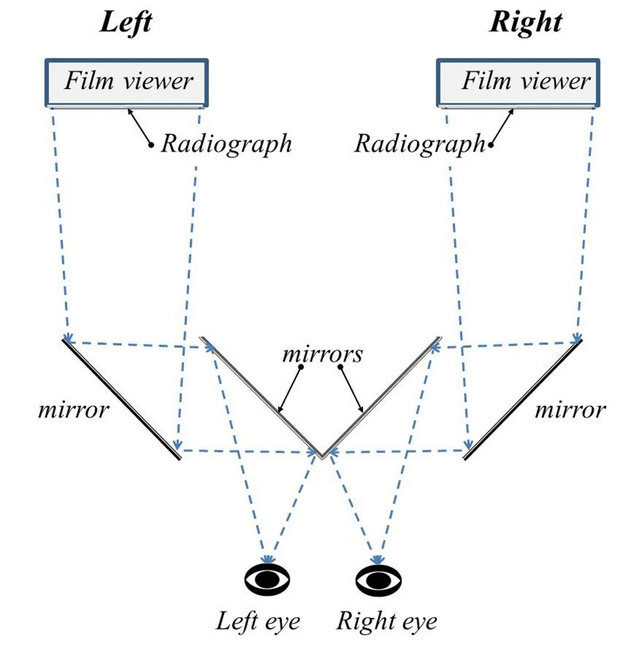
Figure 1. Diagram of a stereoscope.
digital plate which can make stereoradiography much faster and easier.
In this research, the fluorescent screen/digital camera assembly is selected due to its high speed and low cost. The obtained left and right images can be viewed on a laptop computer simultaneously then combined to be displayed in 3D on a 2D or a 3D monitor.
2. Materials and Methods
2.1. Radiography System
A 35 cm × 35 cm × 60 cm light-tight box was first designed and constructed to accommodate a 30 cm × 30 cm Kyokko DRZ Standard fluorescent screen and a Cannon 500D digital camera as shown in figure 2. The fluorescent screen made of gadolinium oxysulfide(terbium) (Gd2O2S:Tb or so called “GOS”) was used to convert transmitted x-ray intensity to light. The digital camera equipped with an 18 - 55 mm and an angle mirror lenses was used to view x-ray image on the screen. The camera software allowed the user to remotely control the camera as well as to display and store the image via USB cable. Because the image sensitive CMOS chip of the camera was also sensitive to x-rays causing noisy signal on the image, the camera was therefore placed behind a lead block while the angle mirror lens reflected the image on the fluorescent screen to the camera. The inner walls of the light-tight box, except the front side where the fluorescent screen was, were also lined with 3 mm thick lead sheets to prevent scattered x-rays within the box from reaching the camera. In practice, the front side of the box would be placed facing the x-ray tube while the specimen was placed right in front of the box. The image appeared on the screen would be viewed by the camera.
2.2. Test Specimens and Results
The first set of test specimens including a video camera and a floppy disk drive were radiographed with x-rays from a Rigaku x-ray tube. The x-ray images of all speci-
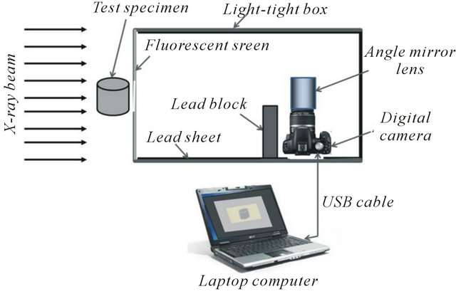
Figure 2. Block diagram of the x-ray imaging system.
mens could be clearly seen on the computer monitor particularly after adjusted by image processing software. Each specimen was then radiographed at the second position, about 6 cm from the first position, by moving the specimen to left or right side along the same specimen plane. The two radiographs were then combined to make a 3D anaglyph image using Analglyph Maker or StereoPhoto Maker software. The anaglyph image could be viewed in 3D on normal LCD or LED monitor by using appropriate color glasses such as red-cyan and red-green. The two radiographs were also converted to an MPO (multiple object) file which could be viewed in 3D on a 3D monitor with or without 3D glasses depending on type of the monitor. The 3D images of all specimens could be satisfactorily viewed but only anaglyph images can be viewed on this paper as showed in figures 3 and 4.
To test 3D perception of the proposed method, a simulated specimen made of 7.5 cm × 7.5 cm × 7.5 cm clay block having 5 cm long nails penetrating from different angles was radiographed with x-rays at 120 kV and 2.5 mA-min at two positions. With red-cyan 3D glasses, its red-cyan anaglyph image showed in figure 5 clearly demonstrates that nails penetrate into the clay block at various angles.
To demonstrate the use of the developed system for inspection of suspicious object, another simulated specimen was made by putting various objects inside a paper parcel including stapler, eraser, scissors, small plastic bottle containing wax and tennis ball containing coins. The objects inside the parcel could be clearly seen in the obtained x-ray images. Its anaglyph image is also showed in figure 6.
3. Conclusions and Discussion
The anaglyph and the MPO images of the test specimens
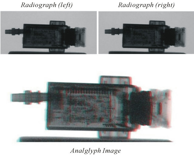
Figure 3. X-ray and red-cyan anaglyph images of the video camera.
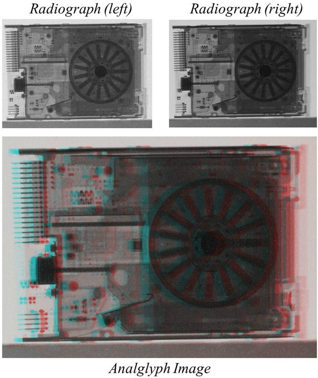
Figure 4. X-ray and red-cyan anaglyph images of the floppy disk drive.
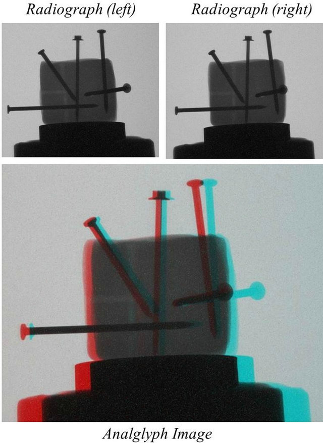
Figure 5. X-ray and red-cyan anaglyph images of the clay block with nails.
gave satisfactory 3D effect. The position and orientation of the five nails were clearly seen. The 3D images of other test specimens also showed depth and orientation of their internal parts. The anaglyph image could be printed out to be used as evidence as could be seen in figures 3-6. In comparison, the MPO image could be viewed only on a 3D monitor or a 3D TV but it was more
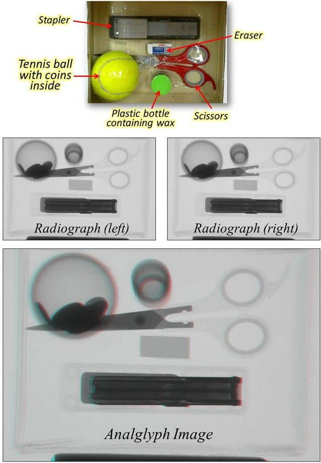
Figure 6. Paper parcel containing various objects with x-ray and red-cyan anaglyph images.
comfortable than viewing the anaglyph image.
With the developed x-ray imaging system using the fluorescent screen/digital camera combination, it takes only less than a few minutes to create left/right images and to combine the two images to make anaglyph or MPO image file. The 3D effect gives much better details than normal 2D radiograph on position and orientation of defects and foreign materials of the test specimen. In conclusion, the developed system and technique can be practically employed for routine inspection of specimens to obtain better information than a single radiograph without spending too much time as required by the film technique. To obtain good 3D effect, the specimen thickness should be taken into account in determining the focus-screen distance as in normal radiographic testing. Moreover, the system and technique can be further improved for real-time inspection of moving specimen such as parcels and packages on conveyor belt.
4. Acknowledgements
The authors would like to express their sincere thanks to Mr. Chalermpong Polee for his assistance and suggestion in operating the x-ray machine and in setting the digital camera to obtain a good image quality.
REFERENCES
- ASTM, “Radiography and Radiation Testing,” Vol. 3, 2nd Edition, Nondestrauctive Testing Handbook, American Society of Nondestructive Testing, 1985.
- IAEA, “Industrial Radiography,” Training Course Series No. 3, International Atomic Energy Agency, Vienna, 1992.
- G. Rosenfeldt, Private Communication.
- 2012. http://www.mikrohamburg.de
NOTES
*Corresponding author.