Modeling and Numerical Simulation of Material Science
Vol.3 No.3A(2013), Article ID:35550,9 pages DOI:10.4236/mnsms.2013.33A003
Computational Multiaxial Fatigue Modelling for Notched Components*
General Dynamics Land Systems—Canada, London, Ontario, Canada
Email: ayhan.ince2@gmail.com
Copyright © 2013 A. Ince. This is an open access article distributed under the Creative Commons Attribution License, which permits unrestricted use, distribution, and reproduction in any medium, provided the original work is properly cited.
Received June 2, 2013; revised July 2, 2013; accepted July 10, 2013
Keywords: Multiaxial Fatigue Life; Fatigue Damage Parameter; Critical Plane; Stress-Strain Analysis; Notch Analysis
ABSTRACT
Fatigue failures of driveline and suspension notched components for ground vehicles under multiaxial loading conditions are common, since most of those components are subjected to complex multiaxial loadings in service. A computational fatigue analysis methodology has been proposed here for performing multiaxial fatigue life prediction for notched components using analytical and numerical methods. The proposed multiaxial fatigue analysis methodology consists of an elastic-plastic stress/strain model and a multiaxial fatigue damage parameter. Results of the proposed multiaxial fatigue analysis methodology are compared to sets of experimental data published in the literature to verify the prediction capability of the elastic-plastic stress/strain model and the multiaxial fatigue damage parameter. Based on the comparison between calculated results and experimental data, it is found that the multiaxial elastic-plastic stress/strain model correlates well with experimental strain data for SAE 1070 steel notched shafts subjected to several non-proportional load paths. In addition, the proposed fatigue damage parameter is found to correlate reasonably well with experimental fatigue data of SAE 1045 steel notched shafts subjected to proportional and non-proportional loadings.
1. Introduction
Most driveline and suspensions components, such as axles and shafts for ground vehicles, are subjected to combined cyclic tension, bending and torsional loads during operations in service. These complex cyclic loadings are defined as multiaxial loadings, where principal stresses rotate and change non-proportionally their magnitudes during a loading cycle. In addition, many of machine components contain notches and geometrical irregularities because of design requirements. These geometric discontinuities cause significant stress concentrations. Multiaxial loading paths produce complex stress and strain states near notches and can cause a fatigue failure even without any evident large-scale plastic deformation. Unfortunately, the combination of multiaxial loading paths and complex geometries of mechanical components is unavoidable in practice and experiments performing durability test are often not feasible because of time and cost considerations. Therefore, analytical and numerical methods are an indispensable approach to conduct fatigue and durability analyses for notched components design process Due to the fact that notch regions are under the effect of multiaxial stress state, the fatigue strength and durability estimations of notched components subjected to multiaxial loading paths require detail knowledge of stresses and strains in such regions. Although Finite Element Analysis (FEA) using commercial software tools can be used to determine notch tip stresses in the elastic and elastic-plastic state induced by short loading histories (a few cycles), such methods are still impractical in the case of long load histories experienced by real machine components. Cyclic loading histories experienced by notched components in driveline and suspension systems may contain from thousands to millions of cycles. Therefore, an incremental elastic-plastic finite element analysis for long loading histories would require impractically long computation times and excessive data storage. For these reasons, more efficient and simpler methods of elastic-plastic stress-strain analysis and fatigue life estimations are necessary for notched bodies subjected to lengthy cyclic load histories.
Local strain based fatigue life prediction of notched components subjected to multiaxial loading paths require detail knowledge of stresses and strains in such regions. Recent research studies [1-3] have shown that the notch correction method can be combined with the cyclic plasticity model to compute the local stress and strain history from the pseudo elastic stress and strain at the notch area. Coupling the notch correction method and the cyclic plasticity to compute the local stresses and strains at critical locations in components provides a great advantage over experiments and incremental elastic-plastic finite element analyses due to its simplicity, computational efficiency, low cost and reasonable accuracy. The multiaxial stress-strain notch correction model proposed by Ince and Glinka [4] is used to compute local stress strain responses using linear elastic FE results of notched components.
Multiaxial fatigue analysis is a very complex process in comparison to uniaxial fatigue. Different from the uniaxial fatigue problem, the multiaxial fatigue involves complex stress and strain states, load histories and fatigue damage parameters relating the fatigue life. In recent decades, a large number of research studies have been conducted to develop a successful multiaxial fatigue damage parameter. Although numerous damage parameters have been proposed during the past decades to predict the multiaxial fatigue failure, most of them are limited to specific load cases and material and there is no universally accepted damage parameter yet. In general, most of the damage parameters can be classified as stress-based, strain-based and energy-based damage parameters. Since there are several good review papers of existing multiaxial fatigue damage parameters can be found in literature [5,6], those damage parameters that are not discussed here. The multiaxial fatigue life prediction remains a challenging problem due to its general wide practical applications in general and the ground vehicle industry in particular; therefore additional research studies should be still required for accurate and reliable multiaxial fatigue assessment.
2. Integrated Multiaxial Fatigue Analysis Methodology
The successful design of machine components subjected to complex multiaxial loadings requires that an effective multiaxial fatigue analysis method be available, which can accurately estimate the fatigue life of those components under complex states of stresses and strains. The main goal of this paper develops and validates a numerically efficient multiaxial fatigue analysis methodology for notched components mainly used ground vehicle suspension and driveline systems. The proposed analysis methodology is composed of:
• An elastic-plastic stress/strain model for computing the material stress-strain response of notched components under multiaxial loadings.
• A multiaxial fatigue damage parameter to estimate fatigue life.
A computational process, shown in Figure 1, is proposed to implement the multiaxial fatigue analysis methodology. The following procedure summarizes the three main computation steps necessary for carrying the methodology.
1) Multiaxial elastic-plastic stress-strain analysis
• Calculate elastic-plastic stress-strain histories at the critical notch location using the input linear elastic stress histories obtained from the linear elastic FE analysis (Multiaxial elastic-plastic stress-strain analysis in Figure 1).
2) Multiaxial fatigue analysis
• Transform the stress and strain time history to potential candidate planes (Stress-strain tensor rotation in Figure 1).
• Calculate fatigue damage on each potential critical plane using the proposed fatigue damage parameter (Fatigue damage parameter in Figure 1).
• Determine the critical plane experiencing the maximum fatigue damage and predict the fatigue life on that plane (Fatigue life prediction in Figure 1).
3) Fatigue damage map
• Plot the fatigue damage on the FE model to obtain the damage map (Damage contour of FE model in Figure 1).
2.1. Multiaxial Elasto-plastic Stress-strain Analysis
FE models are used often to analyze engineering components. A linear elastic FEA can be used to calculate linear elastic stresses/strains for a notched component. Once the elastic stresses/strains are known, the elastoplastic stress-strain analysis (combined the multiaxial notch correction and the cyclic plasticity) can be used to compute actual elastic-plastic stress and strain responses at notch areas. The linear elastic FEA assumes that there is a linear relationship between the applied external load and stress/strain results. Axle and shaft components often experience combined bending and torsion loads. For the case of general multiaxial loading applied to a notched body, the state of stress near the notch tip is tri-axial.
However, the stress state at the notch tip is bi-axial because of the notch-tip stress for a free surface as shown in Figure 2.
Seven fictitious linear elastic stress and strain components  are obtained from the linear elastic FE solution, however the actual elastic-plastic stress and strain components
  at the notch tip are unknown.
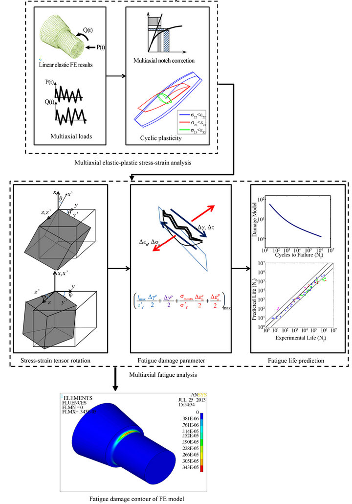
Figure 1. Computational flow chart of the integrated multiaxial fatigue analysis.
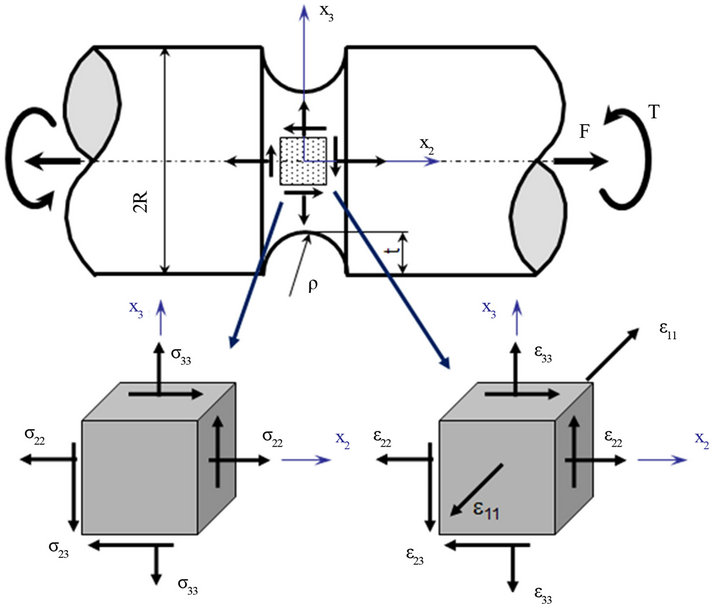
Figure 2. Stress and strain state at a notch tip.
In order to solve the set of seven unknowns actual elastic-plastic stress and strain components at the notch tip, the multiaxial stress-strain notch analysis model proposed by Ince and Glinka [4] is used. The proposed model based on a combination of four equations from the elastic-plastic constitutive and three equations from the equivalence of increments of the total distortional strain energy density, yields the required set of seven independent equations necessary to completely define elastic-plastic notch-tip strain and stress responses for a notched component subjected to multiaxial cyclic loads.
2.2. Multiaxial Fatigue Analyis
The actual stress and strain responses at the notch root of a notched specimen were determined using the analytical modeling approach described in the previous section. Once stress and strain components are determined for the notched component using the approximate analytical approach, the stress and strain components need to be transformed on potential material planes to evaluate fatigue damage on various planes. The fatigue damage is evaluated all potential planes and fatigue failure is assumed to occur on the critical plane with the largest amount of fatigue damage.
Once actual strain and stress responses at notch areas are determined, the proposed multiaxial fatigue damage parameter can be used to estimate the fatigue life. Since the critical plane is defined as the plane experiencing the maximum fatigue damage, the fatigue damage parameter is computed for all potential planes using the actual strain and stress histories rotated on those planes. Since the critical plane is not known before the analysis, the fatigue damage parameter on all potential planes is computed in order to determine the critical plane experienceing the maximum fatigue damage. Since the fatigue life prediction is calculated on the free surface of the notched body and stresses and strains usually get their extreme values on the free surface, the critical plane should be searched on potential planes of the free surface. Therefore, the transformation of stress and strain tensors is computed on planes of the free surface. Figure 3 shows two rotations required to transform the stress and strain tensors from the global coordinate system, x-y-z to the local coordinate system, x'-y'-z'. The local coordinate system, x'-y'-z' is fixed to the plane of interest. The plane of interest is reached by first rotating x-y plane clockwise about z axis by an angle of ![]() and then second clockwise the rotation about x axis by an angle of
and then second clockwise the rotation about x axis by an angle of . Therefore, the free surface can be identified by
  and the plane is perpendicular to the free surface has
It is well known that the local strain approach has been well adapted as a practical engineering method in fatigue assessment of mechanical components. A fatigue damage parameter, which quantifies the fatigue damage as a function of certain stress and strain variables such as normal strain, maximum stress and etc., relates the fatigue damage to fatigue life cycles. In past few decades, a significant number of fatigue damage parameters have been developed and no universal consensus has been reached on the best approach to multiaxial fatigue problem. However, these damage parameters have limitations taking into account mean stress effects, non-proportional hardening, and requirement for additional material constants to characterize the fatigue damage. It has been well known that stress-based damage parameters well define fatigue damage of materials at high-cycle fatigue regimes while the strain-based damage parameters show better fatigue damage estimations at low-cycle fatigue regimes. In order to overcome shortcomings of the existing damage parameters, Ince [7] proposed an original multiaxial fatigue damage parameter based on the maximum damage plane. The proposed damage parameter can be expressed in form of generalized strain amplitude,  :
:
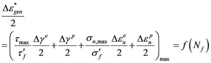 (1)
(1)
Implementation of the proposed multiaxial fatigue analysis methodology, which incorporates the proposed fatigue damage parameter based on the generalized strain amplitude and the elastic-plastic stress-train model is suitable for the design evaluation of notched components used in general engineering applications, especially ground vehicles. This proposed methodology provides more efficient and appropriate analysis approach preferable to more complex and time consuming life prediction methods using non-linear stress-strain analysis.
3. Results and Discussion
The proposed multiaxial fatigue analysis methodology has been implemented in computer programs making it suitable for use in the design evaluation of engineering components. The proposed multiaxial fatigue analysis methodology has been presented in previous sections and
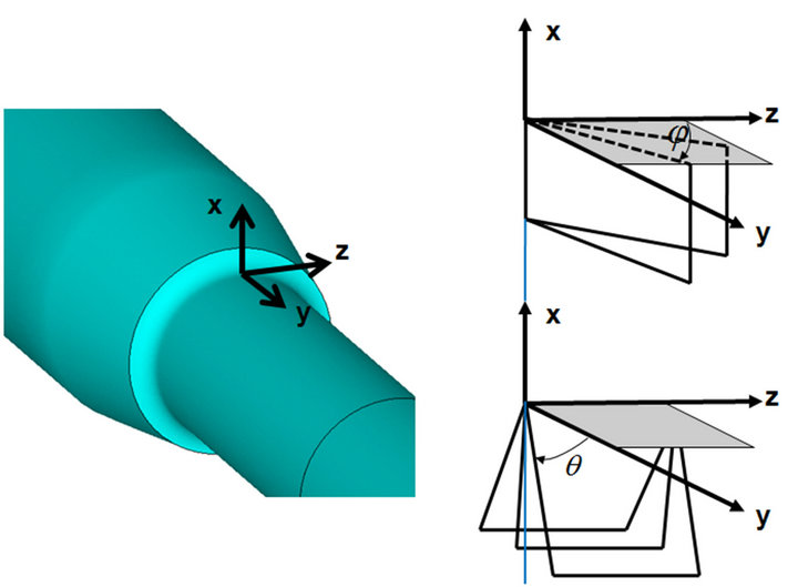
Figure 3. Two plane rotations for a notched body (a) θ rotation about z axis (a) φ rotation about x axis
is now applied to case studies in this section to correlate to various sets of experimental data. The multiaxial fatigue analysis methodology consists of the analytical elastic-plastic stress/strain model to perform the elasticplastic stresses/strains analysis of notched bodies using FE linear elastic stress results and the proposed multiaxial fatigue damage parameter to predict the life of those notched bodies under the multiaxial loadings.
The accuracy of local stress and strain histories is essential for the reliable fatigue life assessment for a notched component. Therefore, stress and strain responses at the notch area of SAE 1045 notched-shaftare determined using an FE-integrated simplified analytical modeling approach. The reliability of the simplified analytical method was verified by validating the analytical method against the experimental data of SAE 1070 steel notched shaft under various non-proportional load paths obtained by Barkey [8].
3.1. Validation of Multiaxial Elasto-Plastic Stress-Strain Analysis
Barkey [8] performed experiments on circumferential notched-shafts subjected to various non-proportional load paths. The notched shafts were subjected to cyclic tension and torsional load histories under conditions of load controls by using Instron and MTS tension-torsion biaxial test frames. Strain gauges were mounted on the notch root for strain measurements. The experimented notch shafts were a cylindrical bar with a circumferential notch similar to that one shown in Figure 2. Each cylindrical specimen was machined from SAE 1070 steel stack to the proper geometry, then heat treated to give uniform material properties.
Pseudo-elastic notch stresses,  , counterclockwise box-shaped cyclic stress paths are shown in Figure 4(a). The box-shaped load path was repeated more than hundred cycles while recording the strains at the notch tip. The box path indicates a high degree of non-proportionality loading. This load path was designed to show regions that axial and shear responses are uncoupled (elastic response) and where they are coupled (elastic-plastic response). Therefore, the box-shaped load path provides a critical test for the proposed stress-strain model for notch tip strain and stress calculations. The maximum nominal tensile and torsion stresses were σn = 296 MPa and ιn = 193 MPa respectively. The corresponding pseudo-elastic notch stresses were
  = 417.3 MPa and
  = 221.9 MPa, respectively. Comparison of the measured and calculated notch strain responses for the counter clockwise box-shaped load path is shown in Figure 4(b). It can be noted that the agreement between the calculated and measured strain responses are qualitatively and quantitatively good. It can be also seen from Figure 4(b) that the proposed elastic-
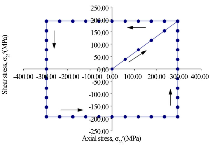
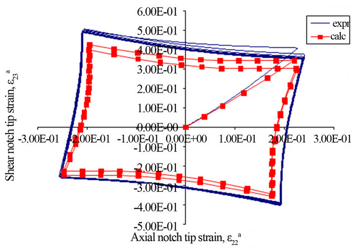
Figure 4. (a) Box cyclic stress/load path—counter clockwise; (b) Experimental and calculated strain paths in the notch tip induced by the box input loading path—counter clockwise.
plastic stress/strain model predicts the elastic unloading at each corner of the box (the axial and shear strain are uncoupled) and followed by the elastic-plastic response to the next corner (the axial and shear strain are coupled).
Several non-proportional cyclic loading paths during, which ratios of the frequency of applied loads were unequal, were applied to the notched-bar specimen. The maximum nominal stresses were σn = 296 MPa and ιn = 193 MPa. Non-proportional load paths from unequal frequencies of applied loads are a common type of loadings experienced by many machine components. Three cycles of tensile load were applied in same time period as one cycle of torsional load (Figure 5(a)). Three cycles of torsional load were applied in same time period as one cycle of tensile load (Figure 6(a)). Axial and shear strain histories obtained from the model and experiments are plotted in Figures 5(b) and 6(b) for the tensile to torsional frequency ratios of 3:1 and 1:3, respectively. As seen from these figures, strain responses computed by the elastic-plastic stress/strain model agree well with experiment strain data in terms of the general trend and numerical strain values.
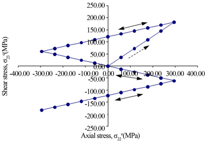
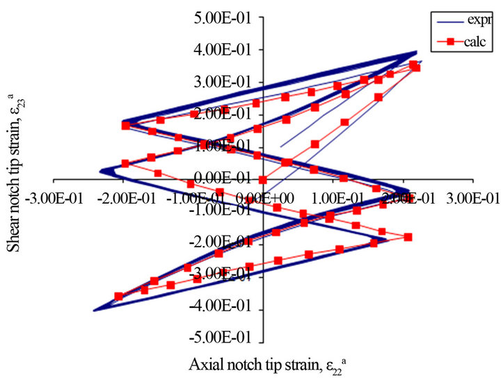
Figure 5. (a) Unequal frequency (ratio 3:1) tension-torsion stress/loading path; (b) Experimental and calculated strain paths in the notch tip induced by the unequal frequency (ratio 3:1) tension-torsion input loading path.
3.2. Validation of Multiaxial Fatigue Analysis
In this section, prediction capability of the proposed multiaxial fatigue analysis methodology which includes the simplified elastic-plastic stress/strain model for performing elastic-plastic stresses-strain analysis at notch areas and the proposed multiaxial fatigue damage parameter for estimating fatigue life of notched bodies is assessed using test data of SAE 1045 notched-shaft [9].
In the 1980’s, members of the Society of Automotive Engineers (SAE) Design and Evaluation Committee created a cooperative testing program to provide experimental data for assessment of existing multiaxial fatigue design procedures and to stimulate research and development of improved multiaxial analysis methods. Kurath, et al. [9] summarized the data collected as the part of committee’s test program.
The SAE shaft specimen, 410 mm long and 40 mm diameter with the gauge length of 100 mm is shown in Figure 7. Each specimen contained shoulder radii of 5 mm. The shaft specimen was designed to initiate crack on the shoulder radius and fatigue life is defined as
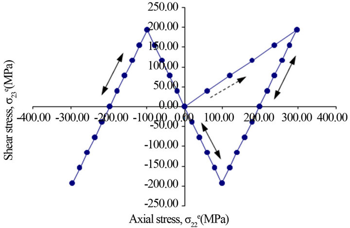
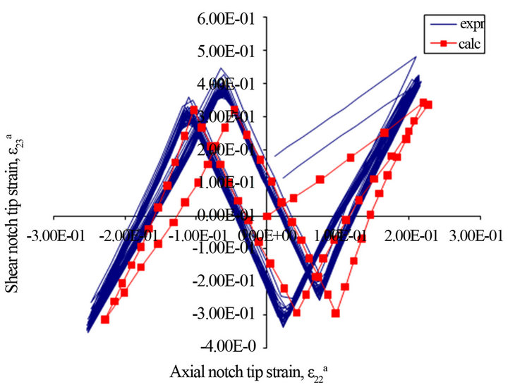
Figure 6. (a) Unequal frequency (ratio 1:3) tension-torsion stress/loading path; (b) Experimental and calculated strain paths in the notch tip induced by the unequal frequency (ratio 1:3) tension-torsion input loading path.
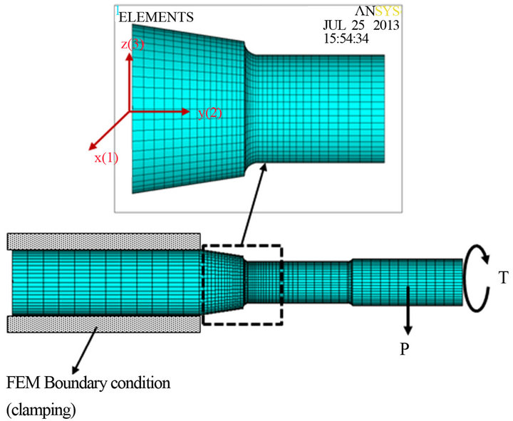
Figure 7. Boundary conditions and applied combined loads (bending and torsion) on the SAE shaft FEA model.
number of cycles, Nf required to grow a length of 1 mm crack on the surface. All specimens were tested in load control, under fully reversed constant amplitude bending, torsion and combination of bending and torsion loadings (in-phase and 90˚ out-of-phase). The ratio of the torsion to bending load was kept constant during each test. Over the experimental program the ratio of the torsion to bending moment Mt/Mb ranged from zero to infinity. The geometry of the SAE notched shaft was modeled in ANSYS finite element code and then meshed using 3-D hexagonal (brick) solid elements and the area near the notch root was carefully refined as shown in Figure 7 to increase the accuracy of the elastic stress-strain results. The FE model contains 34275 nodes and 31968 elements. Boundary and loading conditions are also shown in Figure 7.
Both sets of linear elastic results (elastic stresses) for selected elements (nodal stresses on the critical surface area) were read and converted (using a computer program) to a format readable by the elastic-plastic stress/ strain model. Linear elastic stress results from two load cases (bending and torsion) were combined with actual bending and torsion loading histories using the principle of superposition to obtain increments of pseudo elastic stress histories. The torque Mt induced the ‘linear elastic’ shear stress  at the notch tip and the bending load Mb induced the normal stress
  and hoop stress
 . The increments of hypothetical ‘elastic” stress components
 ,
,  and
and  were used as input for the analytical elastic-plastic stress/strain model.
The accurate stress and strain response in the critical region of the notched shaft is a key factor in the fatigue life prediction. The elastic-plastic stress/strain model using linear elastic FE stress results as an input has been employed to calculate the notch root stress and strain histories at the critical area of the SAE notched shaft subjected to bending-torsion proportional and non-proportional loadings. Figure 8 shows prediction capability of the fatigue damage parameter in estimating fatigue damage and life. As seen from this figure, the damage parameter tends to give non-conservative life predictions for cycles smaller than 104 cycles. On the other hand, the damage parameter shows conservative predictions in high cycle regime. However, both damage parameters perform fairly well in broad range of experimental fatigue data considering a large scatter in experimental data among by the several labs. In addition, the conservative fatigue life predictions in high cycle regime by the damage parameter may be attributed to overestimation of notch stress and strain components by Neuber’s rule. While simple and inexpensive elastic stress histories (linear elastic results of the FE analysis) are used to compute notch root elastic-plastic stress and strain histories, the proposed fatigue analysis methodology provides reasonably accurate fatigue life predictions. The proposed multiaxial fatigue analysis methodology demonstrates satisfactory accuracy and reasonable reliability in the multiaxial fatigue assessment of notched components.
Furthermore, the multiaxial fatigue analysis methodology includes the APDL macro for plotting fatigue damage contour for the critical notch area to visualize the fatigue damage map. The damage contour around notch areas for the SAE shaft under the in-phase loading (the bending load, Mb = 1150 Nm and the torsion load, Mt = 2700 Nm) is shown in Figure 9.
4. Conclusions
The proposed multiaxial fatigue analysis methodology, for performing multiaxial fatigue life prediction for notched components, has been developed and implemented in computer program(s). The multiaxial fatigue analysis methodology incorporates the elastic-plastic stress/strain model and the proposed multiaxial fatigue damage parameter.
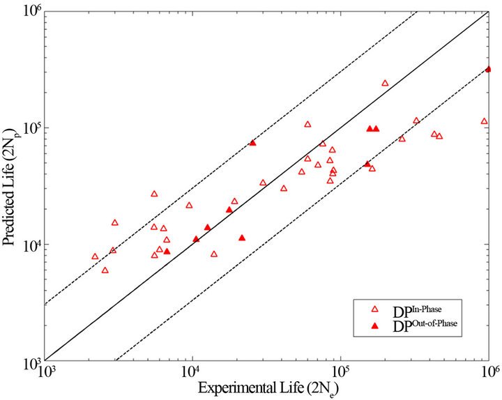
Figure 8. Comparison of Proposed Damage Parameter (DP) with experimental fatigue data of the SAE shaft under inphase and out-of-phase loading.
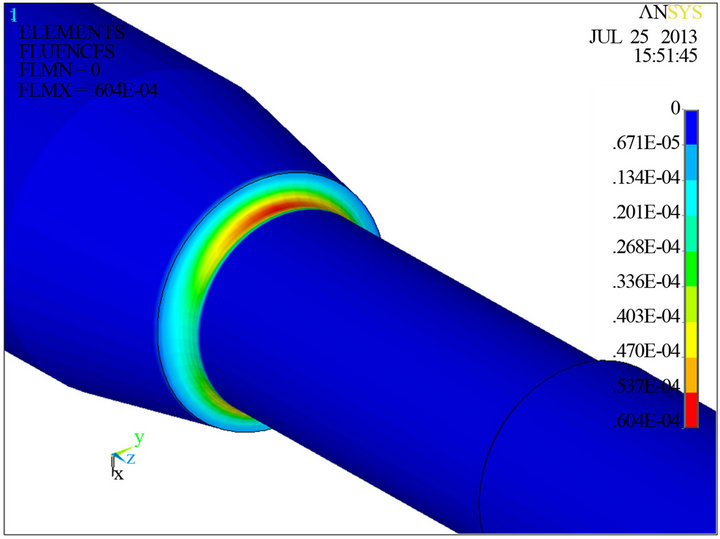
Figure 9. Damage contour around notch for SAE shaft under Mb = 1150 Nm and Mt = 2700 Nm in-phase loading.
Application and validation of the multiaxial fatigue analysis methodology were presented by comparing computed results of the multiaxial fatigue analysis methodology to the experimental data. The accuracy of local stress and strain histories is essential for the accurate fatigue life prediction. Therefore, the elastic-plastic stress/strain model was validated against the experimenttal results of SAE 1070 steel notched shaft. Based on the comparison between the experimental and computed strain histories for the several non-proportional load paths, the elastic-plastic stress/strain model predicted notch strains with reasonable accuracy using linear-elastic FE stress histories.
Since SAE notched shaft specimens represent complex stress-strain state of realistic engineering components, experimental data of the SAE 1045 notched shaft were used to verify the prediction capability the proposed methodology in general and the proposed fatigue damage parameter in particular. The experimental fatigue data of the SAE 1045 notched shaft under proportional and non-proportional loadings were compared to results of the proposed fatigue damage parameter for fatigue lives. The proposed multiaxial fatigue damage parameter based on the generalized strain amplitude on the maximum damage plane satisfactorily correlated experimental fatigue data of the SAE shaft under proportional and nonproportional loadings.
The fatigue damage can be used as a design criterion and concept designs can be analytically assessed so that the predicted fatigue life of the component(s) can satisfy and/or exceed the expected service life. This capability allows design of components to be evaluated and optimized for the service life in the early design phase. The proposed multiaxial fatigue analysis methodology including algorithms and procedures discussed in this study is efficient, robust and reasonably accurate to be used as a design tool for notched components in ground vehicles.
REFERENCES
- V. B. Koettgen, M. E. Barkey and D. F. Socie, “Pseudo Stress and Pseudo Strain Based Approaches to Multiaxial Notch Analysis,” Fatigue & Fracture of Engineering Materials & Structures, Vol. 18, No. 9, 2001, pp. 854-867.
- A. Buczynski and G. Glinka, “Elastic-Plastic StressStrain Analysis of Notches under Non-Proportional Loading Paths,” Proceedings of the International Conference on Progress in Mechanical Behaviour of Materials (ICM8), Victoria, May 16-21, 1999, pp. 1124-1130.
- D. Ye, O. Hertel and M. Vormwald, “A Unified Expression of Elastic-Plastic Notch Stress-Strain Calculation in Bodies Subjected to Multiaxial Cyclic Loading,” International Journal of Solids and Structures, Vol. 45, No. 24, 2008, pp. 6177-6189. doi:10.1016/2008.07.012
- A. Ince and G. Glinka, “A Numerical Method for Elasto-Plastic Notch-Root Stress-Strain Analysis,” Journal of Strain Analysis for Engineering Design, Vol. 48, No. 4, 2013, pp. 229-224. doi:10.1177/0309324713477638
- A. Karolczuk and E. Macha, “A Review of Critical Plane Orientations in Multiaxial Fatigue Failure Criteria of Metallic Materials,” International Journal of Fracture, Vol. 134, No. 3-4, 1995, pp. 267-304. doi:10.1007/s10704-005-1088-2
- B. Li, L. Reis and M. de Freitas, “Comparative Study of Multiaxial Damage Models for Ductile Structural Steels and Brittle Materials,” International Journal of Fatigue, Vol. 31, No. 11-12, 2009, pp. 1895-1906. doi:10.1016/2009.01.006
- A. Ince, “Development of Computational Multiaxial Fatigue Modelling of Notched Components,” PhD. Dissertation, University of Waterloo, Waterloo, 2012.
- M. E. Barkey, “Calculation of Notch Strains under Multiaxial Nominal Loading,” PhD. Dissertation, University of Illinois at Urbana-Champaign, Champaign, 1993.
- P. S. Kurath, D. Downing and D. Galliart, “Summary of Non-Hardened Notched Shaft Rounded Robin Program,” In: G. E. Leese and D. Socie, Eds., Multiaxial Fatigue, Analysis and Experiments, Society of Automotive Engineers, AE-14, 1989, pp. 13-32.
NOTES
*Funding: This research received no specific grant from any funding agency in the public, commercial, or not-for-profit sectors.