Open Journal of Civil Engineering
Vol.06 No.04(2016), Article ID:70355,11 pages
10.4236/ojce.2016.64045
Structural Topology Optimization Method for Morphogenesis of Dendriforms
Xirong Peng
Civil Engineering College, Hunan City University, Yiyang, China

Copyright © 2016 by author and Scientific Research Publishing Inc.
This work is licensed under the Creative Commons Attribution International License (CC BY 4.0).
http://creativecommons.org/licenses/by/4.0/


Received: July 25, 2016; Accepted: September 2, 2016; Published: September 5, 2016
ABSTRACT
The topology optimization method of continuum structures is adopted for the morphogenesis of dendriforms during the conceptual design phase. The topology optimization model with minimizing structural strain energy as objective and subject to structural weight constraint is established by the independent continuous mapping method (ICM) which is a popular and efficient method for the topology optimization of continuum structures. This optimization model is an optimization problem with a single constraint and can be solved by the iteration formula established based on the saddle condition. Taking the morphogenesis of a plane dendriform as an example, the influences on topologies of the dendriform are discussed for several factors such as the ratio of the reserved weight to the total weight, the stiffness and the geometry shape of the roof structure, the height of the design area, and so on. And several examples of application scenarios are presented, too. Numerical examples show that the proposed structural topology optimization method for the morphogenesis of dendriforms is feasible. It can provide diversiform topologies for the conceptual design of dendriforms.
Keywords:
Dendriforms, Topology Optimization, Morphogenesis

1. Introduction
Dendriforms, which was put forward first by a German Frei Otto in the 1960s, is a kind of bionic structure designed based on the shapes and mechanical characteristics of natural trees. The Stuttgart airport terminal (Figure 1(a)) in Germany built in 1991 is a typical engineering designed by Frei Otto. The roof supported by dendriforms with three layers of branches provides a broad space for the airport terminal [1] . Dendriforms have advantages such as the reasonable paths transmitting loads, the broad space

 (a) (b)

 (c) (d)
Figure 1. Engineering buildings adopted dendriforms. (a) Stuttgart Airport Terminal, Stuttgart, Germany [1] ; (b) Changsha railway station in China [3] ; (c) Qatar national convention center [9] ; (d)Tote restaurant, Bombay [2].
achieved by a few bars. Many large-span space structures, such as airports, railway stations, public centers, and so on, adopted dendriforms as supported structures. For example, the Changsha railway station for high-speed trains in China (Figure 1(b)), the Qatar national convention center (Figure 1(c)) and the Tote restaurant in Bombay (Figure 1(d)), etc.
The morphogenesis of the dendriforms is the most important problem during its structural design for its many branches and complicated form. The height, the layer, the number and the location of branches need to be designed. The suitable supported location of the roof structure needs to be determined. Thus, every component of the dendriform conforms to the optimal paths of transmitting loads; and the functional requirements of the building are also met.
There are three kinds of methods for the morphogenesis of dendriforms: the experimental methods, the geometric methods and the numerical methods. Experimental methods have the wet thread method, dry thread method, the beaded thread method and so on. The application of the experimental methods is restricted for their results influenced by model scales [1] . Geometric methods adopt the fractal theory to generate the geometric shapes of dendriforms. Gawell generated geometric shapes of dendriforms based on the L-system fractal theory and introduced an engineering application on the Tote restaurant in Bombay [2] . The dendriforms generated by the fractal method are focused on only the shape characteristics of the trees. Their geometric configurations can be improved by the structure optimization technology to consider the mechanics characteristics of the trees [3] . With the development of the numerical analysis and structural optimization technology, numerical methods are applied to generate the forms of dendriforms, and researches and applications on this aspect become the hotspots. Von Buelow put forward a method of generating the dendriforms by using a genetic algorithm to find the shortest paths [4] . Yue Wu put forward a reverse hanging method for form finding of dendriforms [5] . Qian Zhang studied the form finding of dendriforms based on the sliding cable element [6] . Using the optimization method of skeleton structures, Changyu Cui proposed the form finding method of dendriforms based sensitivity [7] . Meanwhile, he improved the evolutionary structural optimization method (ESO) method, which was a topology optimization method of continuum structures, to generate the optimal topology of dendriforms [8] . Sasaki applied the improved ESO method to design the Qatar national convention center (Figure 1(c)) [9] .
The more rational design can be achieved by the form finding method based on the topology optimization of continuum structures because the optimal topologies with skeleton forms can be obtained, and it is unnecessary to specify some prior data such as the height, the layers and the numbers of branches. But the ESO method [10] adopted at past has some shortcomings such as the low efficiency for its too many optimization iterations, different optimal topologies obtained by taking different deleting rate, and unstable algorithm [11] . The independent continuous mapping (ICM) method, one of the topology optimization methods of continuum structures, has a high solving efficiency because it establishes an optimization model and solves the model by the dual sequential quadratic programming method [12] . In this paper, a morphogenesis method of dendriforms is presented based on the ICM method which has high efficiency. Some factors affected the forms of dendriforms are discussed and some conclusions are followed, which are useful for the topology design of dendriforms. Finally, several application examples are presented to illustrate the feasibility of the proposed method.
2. Topology Optimization Method for Morphogenesis of Dendriforms
2.1. Topology Optimization Model for Morphogenesis of Dendriforms
The morphogenesis of dendriforms is used usually during the conceptual design phase. The usual way is to design a structural topology with maximum stiffness under the vertical loads acting on the roof structures. Thus, it can be formulated as a topology optimization problem of the continuum structure, namely: under the specified consumption of material, within the specified design area, optimizing the topology to maximize the structural stiffness under the specified roof loads. Because the maximum structural stiffness is equivalent to the minimum structural strain energy, the topology optimization model for generating a dendriform boils down to the topology optimization problem with minimizing structural strain energy objective subject to structural weight (or volume) constraint, as shown in Equation (1):
 (1)
(1)
where,  is the topology design variable. e is structural strain energy, W is structural weight.
2.2. Modeling and Solving of Topology Optimization Problem with Minimizing Strain Energy Objective Subject to Weight Constraint
For the topology optimization problem with minimizing structural strain energy as an objective subject to a specified weight constraint, the optimization model can be established by the ICM method as the following process. The discrete topology variables with values 0 or 1 are extended to the continuous topology variables with values in the interval [0, 1] by the approximation of the step function. The element weight and stiffness matrix are identified by the filter functions of weight and stiffness respectively [12] :
 ,
, (2)
(2)
where  and
and  are the weight and stiffness matrix of the i-th element.
  and
and  are the inherent weight and inherent stiffness matrix of the i-th element. The filter functions of weight and stiffness can be taken as power functions:
 ,
, (3)
(3)
where the power  and
and  can take 1 and 3, respectively.
Thus, the elemental strain energy can be expressed as:
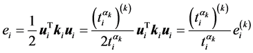 (4)
(4)
where  and
and  are the topology variable and the strain energy of the i-th element at the k-th iteration respectively.
The elemental weight can be expressed as:
 (5)
(5)
Therefore, the topology optimization model established by the ICM method is written as:
 (6)
(6)
To prevent the stiffness matrix to appear singular while the topology variable takes value 0, a small value  is adopted to replace with 0, and it can be taken as
 .
.
Because of the Equation (4) is an optimization problem with a single constraint, the constraint must to be taken as the equality constraint. Otherwise the problem will be an unconstrained problem and become a meaningless problem. Note , and define the active set
 , then, Equation (6) is written as:
 (7)
(7)
The augmented Lagrangian function of the problem is:
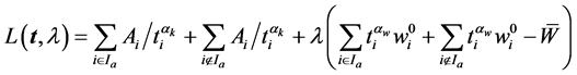 (8)
(8)
The saddle point for the above function taking the extremum condition is:
 (9)
(9)
From it, we obtain:
 (10)
(10)
Substitute Equation (10) into the equality constraint condition of Equation (7)
 (11)
(11)
we obtain
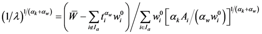 (12)
(12)
Substitute Equation (12) into Equation (10), we have
 (13)
(13)
Considering the interval constraints of topology design variables, namely
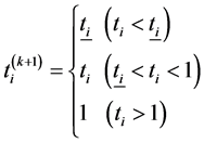 (14)
(14)
Update the active set, and return to Equation (13) to calculate . Terminate the iteration loop while the active set is unchanged. The optimal result
  is the solution of Equation (6). Modify the structure according to the Equation (2), and enter into the next iteration. Iterate until the following convergence criteria is met:
 (15)
(15)
where  and
and  are structural strain energy of the previous and current iteration.
  is the convergence accuracy, and
  is adopted here.
3. Morphogenesis of Dendriforms
3.1. Example 1: The Morphogenesis of Plane Dendriforms
As showed in Figure 2, the design area is a rectangular with sizes of 10 m × 7.5 m. A uniform vertical distribution load q = 1 kN/m is applied on the upper border. An edge with thickness of 0.3 m is used as the roof structure and is the non-design area. A fixed region with width 0.4 m located at the center of the bottom border is regarded as the root of the dendriform. The structural material is steel with the elastic modulus E = 2.1 × 10⁵ MPa and the Poisson’s ratio 0.3. Under a specified constraint of the weight ratio, the optimal topology of the dendriform is obtained by minimizing the structural strain energy, namely maximizing the structural stiffness. The weight ratio is defined as the ratio of reserved weight to the initial total weight.
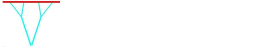
Figure 3 shows the optimal topologies of dendriforms while the weight ratio is changed and the stiffness of the roof structure is unchanged. Optimal topologies of dendriforms are different while the consumption of material is changed. With the increase of the material, the topology of dendriforms is more complicated.
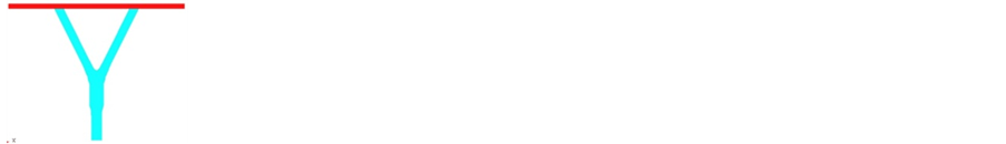
Figure 4 shows the optimal topologies while the stiffness of the roof structures is changed and the weight ratio (10%) is unchanged. For the convenience of dealing with model, the different stiffness of roof structures is simulated by setting different elastic modulus of the material of the roof structure, rather than changing its geometric sizes. Data listed in Figure 4 are the elastic modulus of materials. It can be seen from Figure 4 that the branches of optimal topology of dendriforms are decreased with the increase of the stiffness of roof structures, and are reduced to a pillar in the extreme case.
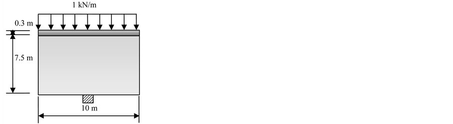
Figure 2. Deign conditions of a plane dendriform.

 (a) (b) (c)
Figure 3. Optimal topologies of dendriforms under different weight ratio (with the increase of the material, the topology is more complicated). (a) weight ratio 5%; (b) weight ratio 10%; (c) weight ratio 20%.


 (a) (b) (c) (d)
Figure 4. Optimal topologies of dendriforms under different stiffness of the roof structure (branches of optimal topology are decreased with the increase of the stiffness of roof structures, and is reduced to a pillar in the extreme case). (a) E = 2.1 × 10⁵ MPa; (b) E = 2.1 × 10⁶ MPa; (c) E = 2.1 × 10⁷ MPa; (d) E = 2.1 × 10⁸ MPa.
Figure 5 shows the optimal topologies while the height of the design area is changed and the stiffness of the roof structures (E = 2.1 × 10⁵ MPa) and the weight ratio (10%) are unchanged. In the cases that the height is small (Figures 5(a)-(c)), the main trunk of the dendriform will not appear. In the cases that the height is large enough (Figures 5(c)-(f)), the main trunk appears; and with the increase of the height of the design area, the optimal topologies of branches of the dendriforms are unchanged, only the height of the main trunk is increased.
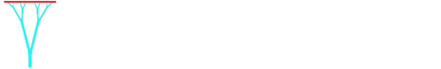
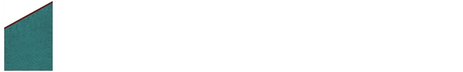
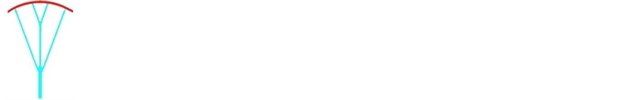
Figure 6 shows the influence of the geometric shapes of roof structures on the optimal topology. An example of the roof structure with a slope shape is showed in Figure 6(a). The optimal topology is different with that of the horizontal roof structure. The big branches are leaned to the high side of the roof. An example of the roof structure with an arc shape is showed in Figure 6(b). A fork shape branch appears, and it is not the case with all binary branch form.
3.2. Example 2: Morphogenesis of Dendriforms for the Bearing Skeleton of Walls
Adopting dendriforms as bearing skeleton structures of walls, not only the loads acting on the walls can be transmitted effectively along the branches of dendriforms, but also a beautiful visual can be achieved. The morphogenesis of plane dendriforms can present diverse options. Figure 7 is an engineering adopting plane dendriforms as the bearing skeleton of walls, Jiangwan Cheng, in Chongqing, China [13] .
As showed in the left figure of Figure 8, the design area is four walls along a square with sizes of 10 m × 10 m and the heights of 8 m. A uniform vertical distribution load q = 1 kN/m is applied on the upper borders of the walls. Along the loading edges, the structures with heights of 0.2 m are used as the beams of the walls to carry the loads, and are non-design area. Fixed regions with the width of 0.2 m at the four corners of the bottom of the walls are taken as the roots of dendriforms. Structural material is steel, and the material properties are same with those in Example 1. The weight ratio of 10% is specified as a constraint, and the minimizing structural strain energy is taken as the objective.
The optimal topology is shown in the right figure of Figure 8. Branches of dendriforms are stretched in the two vertical planes of each corner. In each side of the walls, branches of dendriforms are stretched and intersected at the middle part of the wall,


 (a) (b) (c) (d) (e) (f)
Figure 5. Optimal topologies of dendriforms under different heights of design area (in the cases that the height is small (Figures 5(a)-(c)), the main trunk will not appear; in the cases that the height is large enough (Figures 5(c)-(f)), the main trunk appears; and with the increase of the height of the design area, the optimal topologies of branches of the dendriforms are unchanged, only the height of the main trunk is increased). (a) 5 m; (b) 7.5 m; (c) 10 m; (d) 12.5 m; (e) 15 m; (f) 20 m.


 (a) (b)
Figure 6. Optimal topologies of dendriforms under different shapes of roof structures (left figure: meshes of finite elements; right figure: optimal topology). Different shapes of roof structures lead to different topologies. (a) Roof structure with slope shape; (b) Roof structure with arc shape.

Figure 7. Bearing skeleton of walls of Jiangwan Cheng, Chongqing, China [13] .
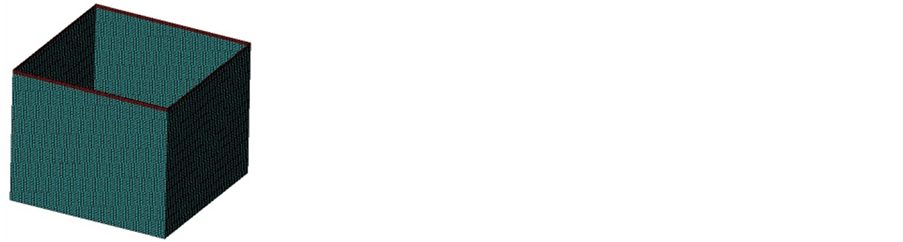

Figure 8. Morphogenesis of dendriforms for the bearing skeleton of walls (left figure: meshes of finite elements; right figure: optimal topology). An arch structure is formed which are widely used in engineering for its wonderful mechanical performance.
and an arch structure is formed which are widely used in engineering for its wonderful mechanical performance.
3.3. Example 3: Morphogenesis of 3-D Dendriforms
As showed in the left figure of Figure 9, the design region is a cube with sizes of 20 m× 20 m × 20 m. A uniform vertical distribution load q = 1 kN/m2 is applied on the upper side of the cube. Along the upper side, a layer with the thickness of 0.5 m is taken as the roof structure, and is specified as non-design region. An area with sizes of 1m×1m in the middle part of the bottom of the cube is fixed and taken as the root of the dendriform. Structural material is steel, and the material properties are same with those in Example 1. The constraint and objective of the model are same with those in Example 2.
The optimal topology is shown in the right figure of Figure 9. It is a form with four branches at each node, and the branch height of the lower layer is greater than that of the upper layer.
3.4. Example 4: Morphogenesis of Multiple Plane Dendriforms
As showed in Figure 10(a), the design area is a rectangular with sizes of 50 m × 7.5 m. A uniform vertical distribution load q = 1 kN/m is applied on the upper border. An
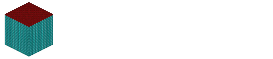

Figure 9. Morphogenesis of 3d dendriforms (left figure: meshes of finite elements; right figure: optimal topology).
 (a)
(a)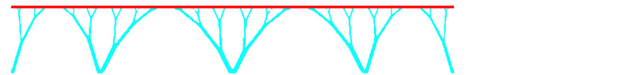 (b)
(b)
Figure 10. Morphogenesis of multiple plane dendriforms. (a) Design conditions of multiple plane dendriforms; (b) Optimal topology of multiple plane dendriforms.
edge with thickness of 0.3 m is used as the roof structure and is the non-design area. The structure is divided into four spans and 5 fixed points are set. Each fixed region has the width of 0.3m and is regarded as the roots of the dendriforms. Structural material is steel, and the material proper-ties are same with those in Example 1. The constraint and objective of the model are same with those in Example 2.
The optimal topology is shown in Figure 10(b). Because the spans are not equal, forms of dendriforms are asymmetric. The adjacent dendriforms also stretch toward the middle part of the spans, and arch structures are formed.
4. Conclusions
1) It is showed from the numerical examples that it is feasible to generate dendriforms by the topology optimization method of continuum structures. Diverse options can be provided by the morphogenesis of dendriforms based on the topology optimization method during the conceptual design phase. Comparing with the dendriforms generating by the fractal methods which don’t consider the mechanical performance of dendriforms, the forms generated by the presented method achieve the maximum structural stiffness. Comparing with those methods based on mechanic models which need to specify design parameters such as the heights and the number of layers, branches at each node, and so on, the presented method can provide larger design space and seek more optimum topology of dendriforms because it is not necessary to specify design parameters.
2) The stiffness of the roof structures has significant effects on the optimal topology of dendriforms. Therefore, the roof structure should be analyzed together with the design area and be involved in the optimization process, and its stiffness should be simulated accurately.
3) The ratio of the structural weight has significant effects on the optimal topology of dendriforms. By setting a proper weight ratio to make the stiffness of the dendriform be similar to that of the roof structure, an ideal topology can be achieved.
4) The design region and the geometric shape of the roof structure have significant effects on the optimal topology of dendriforms. The parameters should be specified and simulated accurately during the conceptual design phase.
Acknowledgements
This work was supported by Natural Science Foundation in Hunan province of China (2016JJ6016) and by Department of Education in Hunan Province of China (15C0247).
Cite this paper
Peng, X.R. (2016) Structural Topology Optimization Method for Morphogenesis of Dendriforms. Open Journal of Civil Engineering, 6, 526-536. http://dx.doi.org/10.4236/ojce.2016.64045
References
- 1. Riann, I.M. and Sassone, M. (2014) Tree-Inspired Dendriforms and Fractal-Like Branching Structures in Architecture: A Brief Historical Overview. Frontiers of Architectural Research, 3, 298-323.
http://dx.doi.org/10.1016/j.foar.2014.03.006 - 2. Gawell, E. (2013) Non-Euclidean Geometry in the Modeling of Contemporary Architectural Forms. The Journal of Polish Society for Geometry and Engineering Graphics, 24, 35-43.
- 3. Li, R. (2014) Research on Branching Structures Based on Fractal Theory. Barbin Institute of Technology, Harbin. (In Chinese)
- 4. von Buelow, P. (2007) A Geometric Comparison of Branching Structures in Tension and Compression versus Minimal Paths. Proceeding of IASS 2007, University IUAV of Venice, Venice, 252.
- 5. Wu, Y., Zhang, J.L. and Cao, Z.G. (2011) Form-Finding Analysis and Engineering Application of Branching Structures. Journal of Building Structures, 32, 162-168. (In Chinese)
- 6. Zhang, Q., Chen, Z.H., Wang, X.D. and Liu, H.B. (2015) Form-Finding of Tree Structures Based on Sliding Cable Element. Journal of Tianjin University (Science and Technology), 48, 362-371. (In Chinese)
- 7. Cui, C.Y., Jiang, B.S. and Cui, G.Y. (2013) The Sensitivity-Based Morphogenesis Method for Framed Structures. China Civil Engineering Journal, 46, 1-8.
- 8. Cui, C.Y. and Yan, H. (2006) An Advanced Structural Morphogenesis Technique—Extended Evolutionary Structural Optimization Method and Its Engineering Applications. China Civil Engineering Journal, 39, 42-47.
- 9. Sasaki, M. (2007) Morphogenesis of Flux Structure. AA Publications, London.
- 10. Huang, X.D. and Xie, Y.-M. (2010) A Further Review of ESO Type Methods for Topology Optimization. Structural and Multidisciplinary Optimization, 41, 671-683.
http://dx.doi.org/10.1007/s00158-010-0487-9 - 11. Sigmund, O. and Maute, K. (2013) Topology Optimization Approaches—A Comparative Review. Structural Multidisciplinary Optimization, 48, 1031-1055.
http://dx.doi.org/10.1007/s00158-013-0978-6 - 12. Sui, Y.K. and Ye, H.L. (2013) Continuum Topology Optimization Methods ICM. Science Press, Beijing, 1-27.
- 13. Liu, X. (2014) Morphogenesis Research for Branching Skeleton Structures of Wall. Barbin Institute of Technology, Harbin, 6-7.